Rupin Chheda
-
Project Milestone: It's Alive — Motion Modes Fully Functional!
07/07/2025 at 06:09 • 0 commentsBig update! The stepper controller firmware has reached a stable, working state — and I’m happy to report that all major features are now live and tested!
✅ Core Features Now Working
Here’s what’s running smoothly:
-
CW (Clockwise) Mode – Tap the encoder, and the motor rotates smoothly in one direction.
-
CCW (Counter-Clockwise) Mode – Same deal, but in reverse!
-
ARC Mode – The star feature. Users define the left and right limits using the Auxillary buttons. Once saved, the motor oscillates smoothly between the two ends.
-
Play/Pause – Pressing the encoder switch now pauses or resumes the motion, regardless of mode. Super intuitive.
-
Non-Volatile Memory – The system now remembers the last mode and positions even after power-off. This makes it ideal for installations or embedded setups — set it once and forget it.
🧠 How It Works for the User
-
Choose your mode (CW, CCW, ARC) while the motor is paused.
-
In ARC mode, press the Aux buttons and rotate to set endpoints, then press the Save/Erase Button to save the position.
-
Press the play button to start motion.
-
Pause or play any time with a single click.
-
Power it off and on — your config is still there!
🧪 What’s Next?
-
Implement I2C daisy-chaining for multiple synchronized motors.
-
Create a printable case or mounting bracket.
-
Start testing with real-world mechanical linkages and kinetic art setups.
🎊 This is a huge step forward in making stepper motor control plug-and-play for non-engineers. No code, no libraries — just intuitive hardware and motion.
More to come soon!
-
-
First Assembly & Debugging Surprises
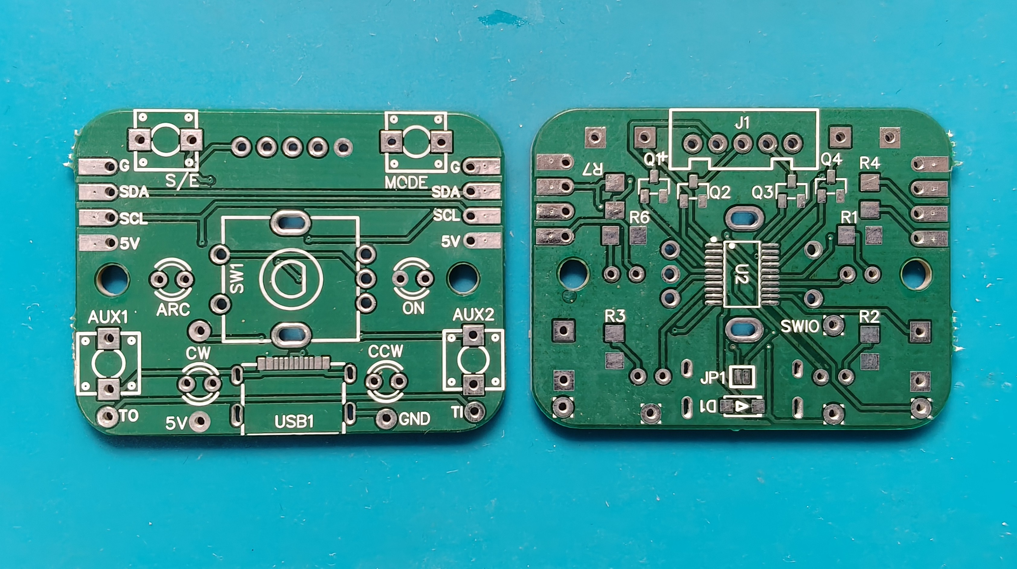
07/02/2025 at 03:03 • 1 commentThe PCBs finally arrived from Lioncircuits, and I kicked off the initial hardware bring-up!
![]()
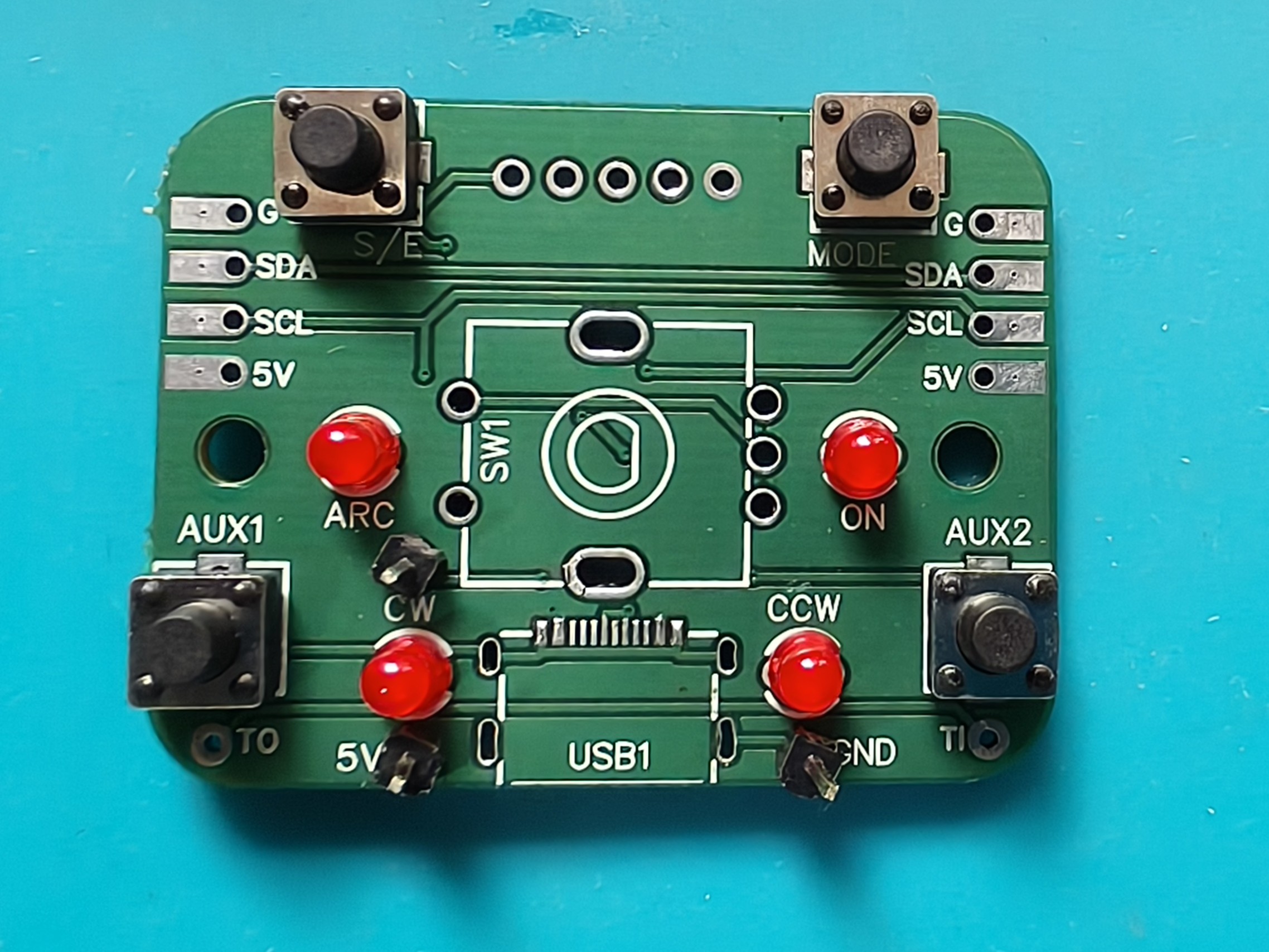
Assembly Progress
-
The USB-C port footprint didn’t align with the mounting holes — a mechanical mismatch. This means the USB port won't be populated in this revision.
-
I began with soldering SMD resistors:
-
1kΩ for LEDs
-
10kΩ pull-ups for I2C (SDA & SCL)
-
-
Next came the A03416 MOSFETs, followed by a careful hand-solder of the CH32V003 microcontroller.
![]()
-
To test programming, I added a simple pin header breakout for 5V, GND, and SWIO, which worked flawlessly.
-
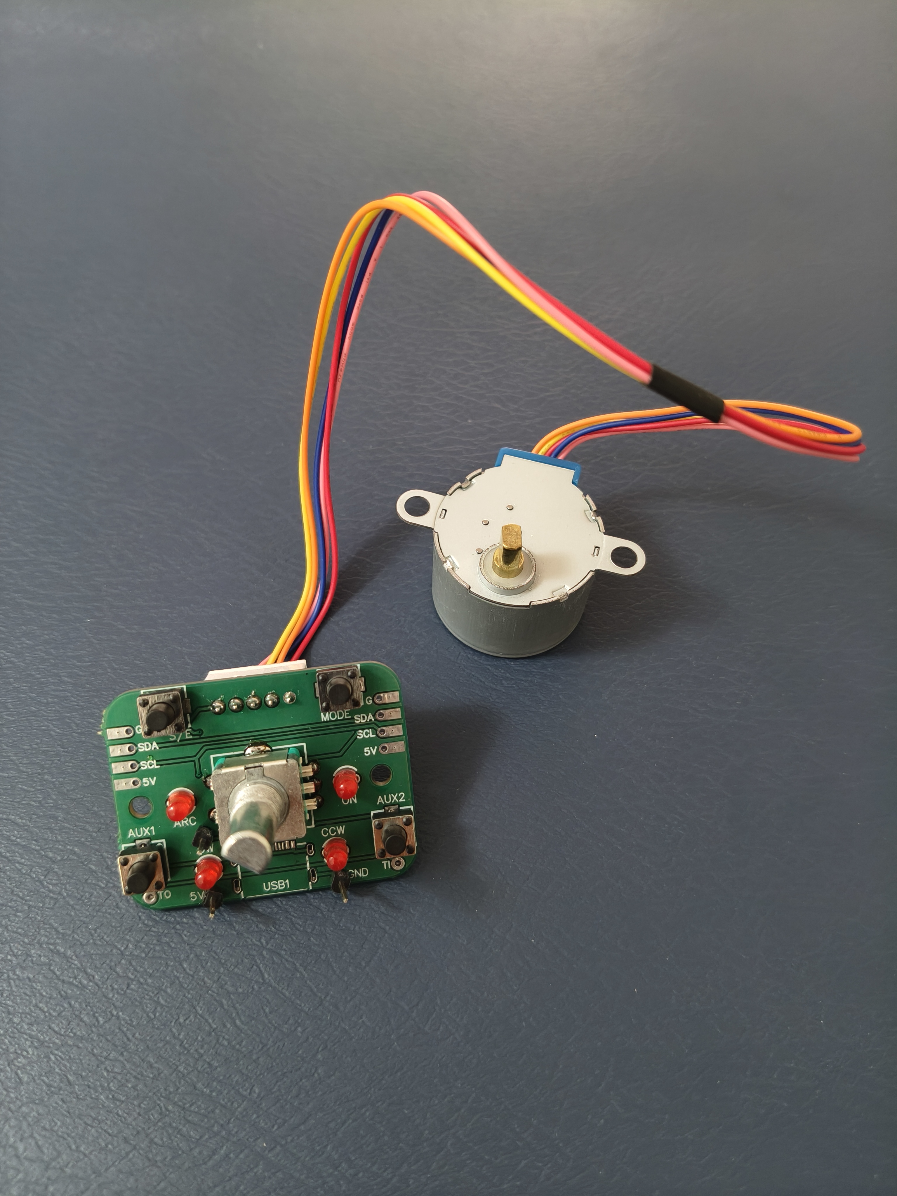
Finished off with all through-hole parts: switches, LEDs, the rotary encoder, and the stepper motor connector.
All components passed individual tests — switches and LEDs functioned correctly.
![]()
![]()
Debugging the Stepper Motor
I encountered a strange issue — the stepper motor wouldn’t move.
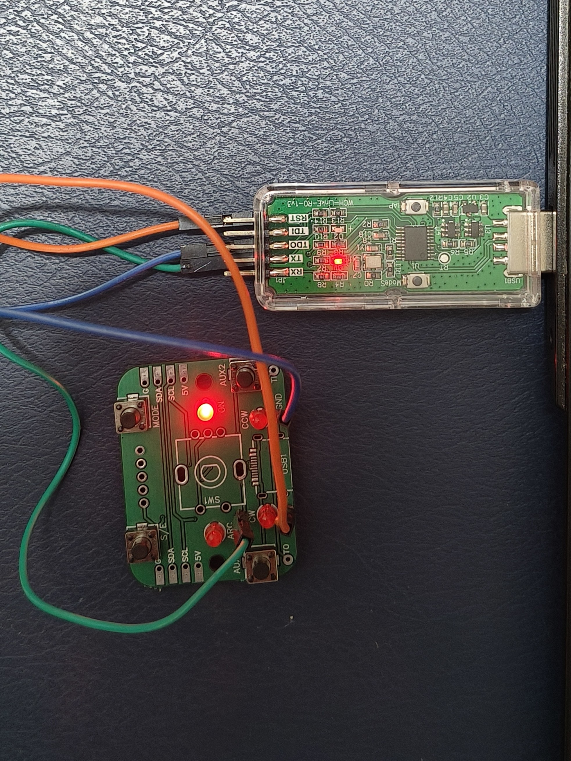
To isolate the problem, I connected an LED in place of the motor to observe the pin sequences. Strangely, the LED connected to PD7 wasn’t toggling. I checked the MOSFET for shorts — no issues there.
After digging into the datasheet, I realized the root cause:
PD7 is also the NRST (reset) pin, which is pulled high at startup, unintentionally turning the MOSFET on and grounding the connected pin.Solution?
I used the WCH-Link Utility to reconfigure PD7 as a general I/O pin. Once that was done, the sequence worked — and the stepper motor spun beautifully.
![]()
⚡ Power Concerns
While testing the motor, I noticed the power LED dims significantly when the stepper coil energizes. Measuring current draw showed around 200mA, which is expected.
The issue appears to be a voltage dip when coils energize. I’ve switched to an external power supply for now, but will be adding a beefy capacitor across 5V and GND to buffer the current surges and stabilize power delivery.
🧪 What’s Next?
-
Fix the USB-C footprint in the next revision
-
Tune power filtering with appropriate capacitance
-
Begin firmware work for motion configuration and I2C chaining
-
Build mounting brackets and start integration with real-world mechanisms
More to come — but for now, I’m thrilled the first spin of the motor is live!
-
Accesible Motion with Steppers
A plug-and-play unipolar stepper motor controller built around the ultra-low-cost CH32V003 MCU, designed for makers, educators, and designer