sotiris barlakas
-
Raspberry Pi zero solar powered server
07/21/2025 at 13:49 • 0 commentsAfter managing to have a sensor node based on ESP32 running using solar power and battery during nights and constantly gathering data, the next step is to set up a "brain" for our vineyard. A central server that can gather data from one ore more distributed sensor nodes and store that data or upload them to the cloud. As the vineyard hasn't internet access, for now the server will just save data locally in order for them to be accessed directly by reading the SD card.
The current endeavour is split in these parts:
1) Setup Raspberry Pi (initially AC powered)
2) Create a python server script that receives and saves data
3) Create code for the ESP32 to connect to the server and send data from the sensor connected to it.
4) Finally, power the Raspberry Pi using solar power
Raspberry Pi Setup
I had never worked with a raspberry before so my first goal was to set up a raspberry pi zero by installing an operating system to am SD card, and boot into it. To my embarrassment and surprise I realized quickly that you can't just buy a raspberry pi alone, press a button and begin working with it. You need some peripherals.
1) An hdmi cable to access it through a monitor.
2) An micro hdmi adapter (because the hub in the pi is micro HDMI type)
3) An SD card to install the OS
4) An SD card USB adapter to plug in a laptop, and upload the downloaded OS to the SD card
5) Keyboard and mouse
6) USB hub because raspberry pi zero has only 2 micro-usb ports (and one is taken for powering)
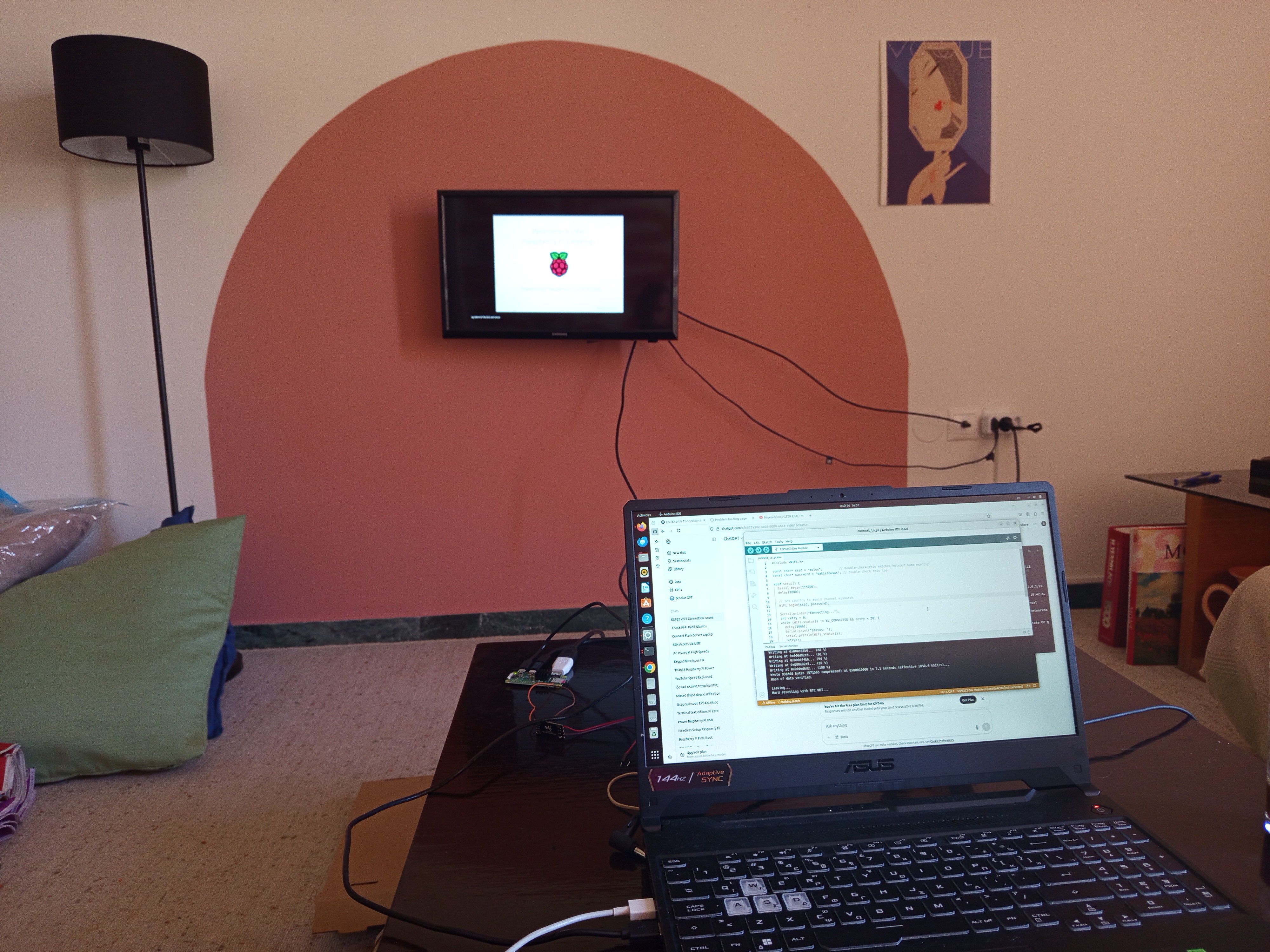
So after purchasing the parts and following an online tutorial to install the OS, I was finally in.
![]()
To be sincere I didn't have a spare keyboard and I didn't want to buy one so I needed to find an alternative.
At first I activated from the settings the display keyboard function but writing code with that keyboard would soon turn my life into hell. So after a bit of searching I decided to set up a headless (meaning remote) connection to the raspberry that would enable me to control the raspberry from any device. In Linux this is commonly done after establishing a SSH connection. To do so, the raspberry pi and the device that you try to connect should be on the same Wi-Fi network. Alternatively the device must be connected to the Wi-Fi hotspot of the raspberry pi. I found that more generic and straightforward to implement so I started creating a hotspot from the raspberry pi.
This is very straightforward from the GUI of the pi, and all you have to do is to set a name, a password, and activate it.
Then from another device, I connected to that Wi-Fi hotspot. Then, in order to connect to the raspberry pi and gain access to it, we have to find its IP address. As we have access to the Pi from the monitor and mouse, we can find its IP by opening a terminal and typing:
hostname -IThen we can connect to the raspberry pi by entering in the terminal of the other device:
ssh {pi_username}@{ip_address}We are in!!
Now we can use terminal commands to do whatever we want with the Raspberry Pi. We don't longer need the mouse and the monitor!
But first we have to make sure that the Pi will activate the hotspot after every boot. We can set this up easily from the settings of the hotspot.
Create a python server
Now that the raspberry pi is set up and we can access it from any device to program it or inspect we are ready to actually start using it.
First thing that we are going to try is to create a very simple python server using the Flask library. The functionality of the server initially will be a simple Hello World message print. Later, the server must be able to accept data from the connected client (aka the ESP32) and save them locally.
The code for the basic server setup is this:
from flask import Flask

app = Flask(__name__)

@app.route('/')
def hello():
    return "Hello, World!"

if __name__ == '__main__':
    app.run(host='0.0.0.0', port=8000)
The code for the server that receives data and saves them locally is:
import csv
from datetime import datetime
from flask import Flask

app = Flask(__name__)
@app.route('/data', methods=['POST'])
def receive_data():
    data = request.json
    print(f"Data received: {data}")

    with open('/home/dev/data_log.csv', 'a', newline='') as f:
        writer = csv.writer(f)
        # Write header if file is empty
        if f.tell() == 0:
            writer.writerow(['timestamp'] + list(data.keys()))
        writer.writerow([datetime.now().isoformat()] + list(data.values()))

    return "Data received successfully!", 200
One final step is to make the server script running each time the raspberry pi boots.
To do that we use a systemd service.
1) First type this to create a service file.
sudo nano /etc/systemd/system/myscript.serviceReplace myscript with any name you like.
2) In this new file we paste the following:
[Unit]
Description=Run My Python Script After Boot
After=network.target

[Service]
ExecStart=/usr/bin/python3 /home/pi/myscript.py
WorkingDirectory=/home/pi
StandardOutput=inherit
StandardError=inherit
Restart=always
User=pi

[Install]
WantedBy=multi-user.target
Of course the following lines:
/home/pi/myscript.py
WorkingDirectory=/home/piShould be changed to match the path and name of your script.
3) Next, ensure that your script is executable.
chmod +x /home/pi/myscript.py
4) Finally enable the service:
sudo systemctl daemon-reexec
sudo systemctl daemon-reload
sudo systemctl enable myscript.service
We are ready. Reboot the raspberry and check that it works. To check the status of the service (along with logs from our script)
sudo systemctl status myscript.serviceCreate code for the ESP32 to connect to the server and send data
What we need next, is to also upload code to the ESP32, to configure it as a client that connects to the server (Raspberry Pi), and sends data in order to be saved locally.
#include <WiFi.h>
#include <HTTPClient.h>

const char* ssid = "pii"; // your hotspot SSID
const char* password = "12345678"; // your hotspot password
const char* serverUrl = "http://10.42.0.1:5000/data"; // <-- use your Pi IP

void setup() {
  Serial.begin(115200);

  WiFi.setMinSecurity(WIFI_AUTH_WPA_PSK);
  WiFi.begin(ssid, password);

  Serial.print("Connecting to WiFi");
  while (WiFi.status() != WL_CONNECTED) {
    delay(500);
    Serial.print(".");
  }
  Serial.println("\nConnected!");

  // Send data
  if (WiFi.status() == WL_CONNECTED) {
    HTTPClient http;
    http.begin(serverUrl);
    http.addHeader("Content-Type", "application/json");

    String jsonData = "{\"temperature\":24.5,\"humidity\":60}";
    int httpResponseCode = http.POST(jsonData);

    Serial.print("HTTP Response code: ");
    Serial.println(httpResponseCode);

    String response = http.getString();
    Serial.println("Server response:");
    Serial.println(response);

    http.end();
  } else {
    Serial.println("WiFi not connected!");
  }
}

void loop() {
  // Nothing here for now
}
The code runs in the solar powered ESP32, that we set up as explained in the previous logs.
Power Raspberry Pi using sun
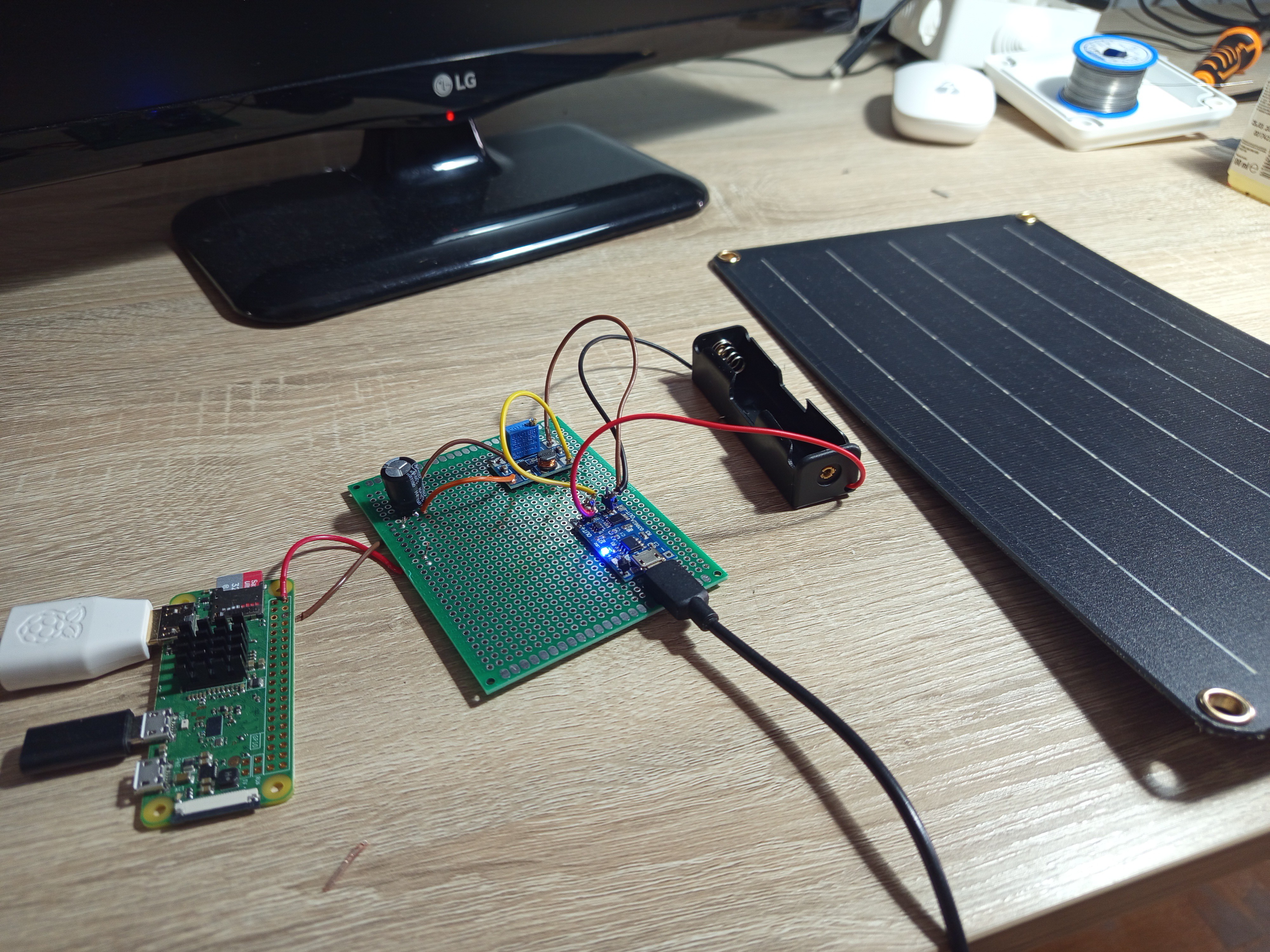
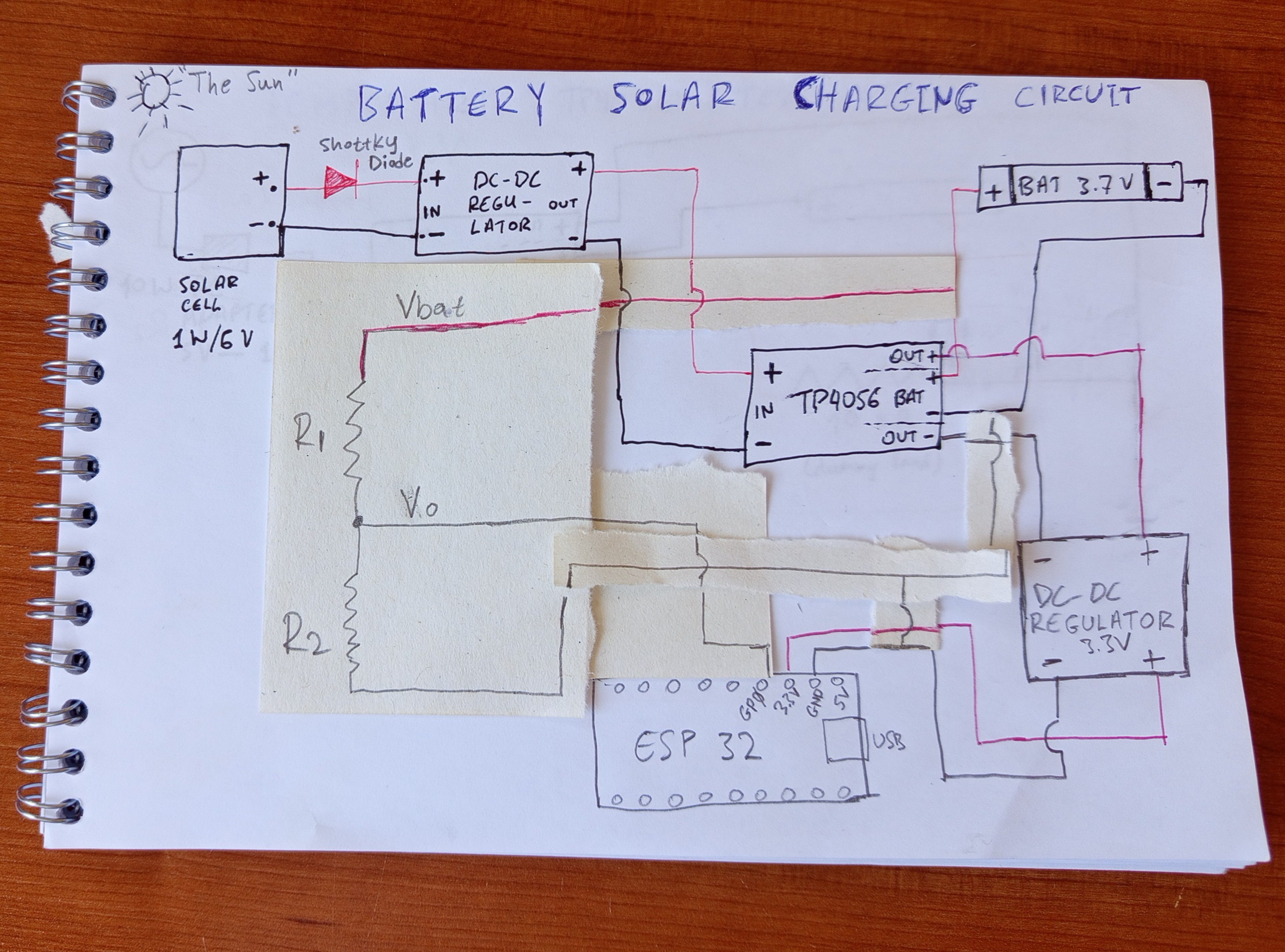
The system functions just fine, but we have to power the Raspberry Pi using solar power in order to deploy in the field. For that we equipped with a 5W solar panel with a regulator and USB output to make our life easier. Again (as in the ESP32 case) we use the TP4056 module to manage the charging of the battery. We will also need a DC voltage regulator to step the voltage up for the Raspberry as it works at 5V and the TP4056 uses the battery power which nominal value is 3.7 volts.
![]()
It's worth mentioning here that in contrary to the ESP32 solar setup, here we didn't connect the load (the Raspberry Pi) to the output pins of TP4056, but directly to the battery poles. This was decided, because we noticed that the TP4056 can't provide with steady power. And we noticed that during the boot of the Raspberry Pi the voltage dropped instantaneously, and the Pi rebooted. The sensitivity of the Raspberry Pi to current spikes during boot suggests adding a 1000 µF, 10 V capacitor in parallel between the voltage regulator and the Raspberry Pi to buffer power and help manage sudden drops in voltage.
This is it! The core of our project is ready and functioning. We have created prototypes of the brain of the vineyard and a sensor node. The next important step is to put everything in waterproof enclosures, and test the system in the vineyard!
-
First solar powered ESP32 Node
06/24/2025 at 09:18 • 0 commentsIntroduction
In this log, I’ll document my first real hands-on step in bringing the vineyard project to life: creating a solar-powered ESP32 node. It's a small but essential milestone that will teach me the fundamentals of powering electronics off-grid — and help me better understand the challenges ahead.
Goal
Build and test a standalone ESP32 microcontroller powered by a solar panel and battery system. The node should be able to operate continuously and send data to the central control unit. In our first project, it will send a message with the current battery voltage.
The primary goal is not just to succeed, but to learn through each failure and iteration.
After a bit of searching (there are a lot of similar projects online) I found out that the main components of a solar powered microcontroller are the following:
Microcontroller (obviously... ESP32-C3 mini is the cheapest I managed to find, is compact and works perfectly)
Solar panel (1 watt is enough to begin with)
TP4056 charging module (super important to manage the safe charging of our battery, it is a BMS actually
18650 lithium-ion battery (very common rechargeable battery. 2-3 mAh is good to begin with)
A voltage regulator (buck/boost converter) module to regulate voltage input from solar panel before feeding it to TP4056. The reason for this is that the TP4056 input voltage must be 4.5-5.5V and the solar panel outputs a variable voltage depending on the sunlight
A voltage regulator (buck converter) to regulate voltage from the TP4056 to the ESP32 because it accepts 3.3V but TP4056 outputs something between 4.2 and 3.5 (the voltage of the battery)
A Shottky diode to prevent current from returning to the solar panel during night
Breadboard + jumper wires (of course)
Multimeter (very important for testing and learning)
The development of the project was split in discrete steps to gain experience with the individual components and learn their behaviour.
3 Demos were planned:
D1: Measuring of battery voltage with the microcontroller
D2: Charge the battery with the TP4056 using AC adapter
D3: Combine D1 and D2 in a single circuit and connect to solar panel
Demo 1
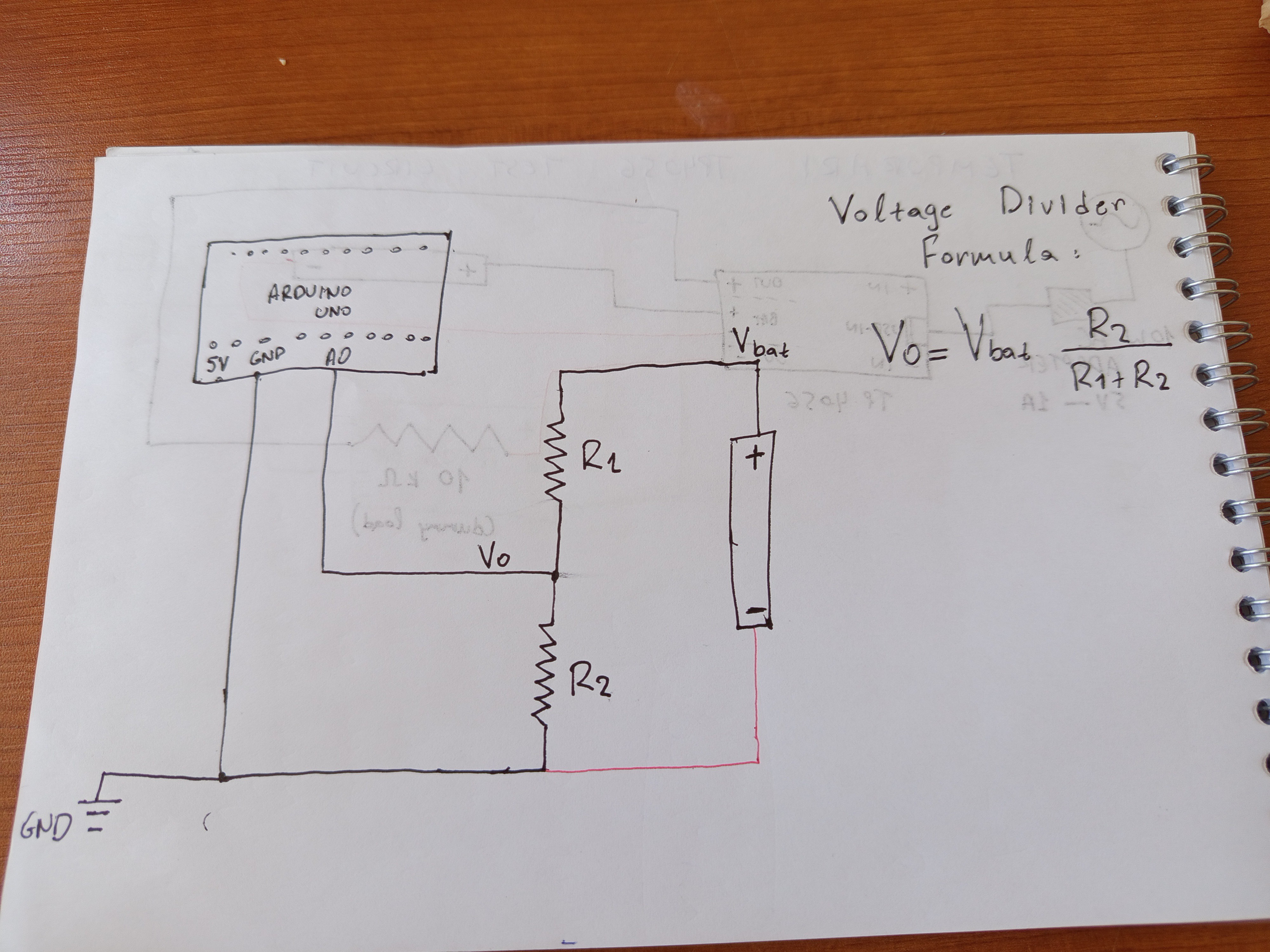
The goal here is to get the voltage of the battery in the analog pin of ESP32. The voltage divider circuit is necessary because ESP32 accepts maximum voltage of 3.3 while the battery voltage is between 3.3 and 4.2. the voltage divider helps us reduce the voltage in a known amount, measure the reduced safe voltage and estimate the real voltage of the battery.
![]()
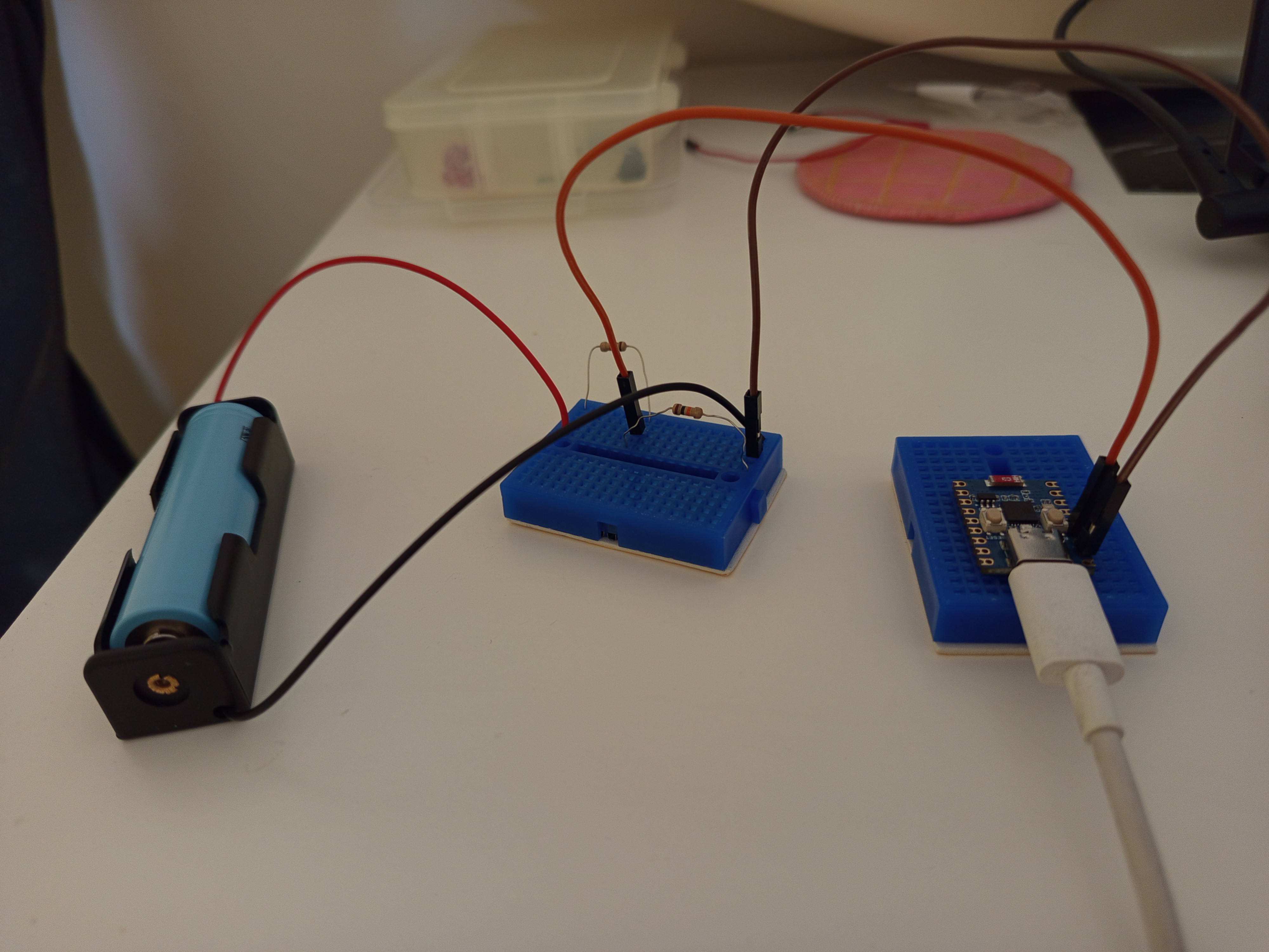
A photo of the circuit is shown in the image below:
![]()
Demo 2
The second demo was about getting TP4056 to work and manage the charging of the battery. For simplification, the TP4056 was charged using an AC wall adapter and not solar panel.
The circuit is shown in the image below:
![]()
Demo 3
Finally, the third demo was to connect the two partial circuits, to try measuring the voltage of the battery while it charges.
The combined circuit is this:
![]()
During this step a problem was realised. When the battery charges its voltage variates according to the charging voltage, but it usually is approximately 4.2volt. So measuring its voltage is pointless. When the battery discharges it's voltage stabilises at its true value.
Lesson learned:
Measuring battery voltage during charging is pointless.
Another problem here was the voltage regulator I bought.
The voltage regulator (mp1584) I bought is not suitable for regulating voltage between battery and esp32 because it has an Input voltage range between 4.75V-23V which is high. The battery will output something between 4.2 and 3.3. And the regulator must regulate this to 3.3 V exactly to power the esp32 safely. So input voltage is lower than the threshold so the voltage regulator shuts down, and the ESP32 doesn't receive any power.
Lesson re-learned (as I have been there before):
When purchasing electronics, look carefully for the specs that your project requires, but still as you can't foresee sometimes you buy the wrong component. It's ok (as long as it is not so expensive).
So I bought a new regulator. And now it works perfectly to keep the voltage at 3.3 volts and power ESP32.
Then it was time to also connect the solar panel to the circuit.
We need a Shottky diode and another voltage regulator. The voltage regulator between the solar panel and TP4056 is supposed to regulate the voltage from the range of 2 to 7 volts that the panel outputs to the range 4.4 to 5.5 that the TP4056 safely operates on. The regulator I had was the same as above (input voltage 4.75-17). So I thought that it would decently when the panel receives a fair amount of daylight and outputs voltage higher than 5 volts. Of course if voltage drops lower than 4.75 volts the regulator will shut down and the charging will stop. So I finally put it under the sun and wait to see the TP4056 starting. But the only thing I saw was its led lights flickering dimly! Why?
The voltage in the solar panel pins was something like 6 volts. So it should be working right?
After a bit search I found out that TP4056 operates at 1A. But the solar panel max current is 0.2A. It is a 1 watt operating at 5-6 volts so given the type Power= Voltage x current everything makes sense. But why is this a problem? I continued my research. I found out that the solar panels on general are current-limiting devices.
A current-limiting devices can't provide larger current than its maximum. So if it is required to provide larger current, the voltage drops! It is called voltage sag. This is done in order for the Power equation to be satisfied. We can't generate more power than the available! We have max 1 watt available so if we demand 1 A from the panel the voltage must drop to 1 volt.
Consequently the voltage regulator didn't receive enough voltage so it shut down.
So that's why the TP4056 was flickering and didn't work! It didn't receive enough voltage.
Solution:
One solution to this problem would be to change the solar panel in order to be able to handle higher current. Another solution to this (in order to avoid the replacement of the solar panel) is to increase the internal resistance (Rprog) of the TP4056 in order to expect lower current. (The Rprog resistor sets the charging current of the TP4056). There are lots of tutorials online on how to do this. A bit of soldering is required. (EDIT: THIS IS HARD. The Rprog resistance is really tiny.) I had to buy a brand new soldering iron because the one I used so far was old and not so accurate (it was my grandpa's - who was an electrician). I also bought thinnier solder and flux (which indeed makes soldering quite easier!) The result is shown in the image below:
![]()
Lesson learned:
When combining electronics, pay attention not only to the voltage but also to the current.
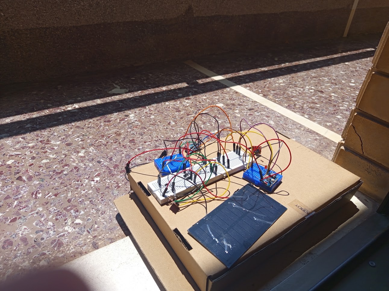
Finally after the aforementioned push-backs and iterations I managed to put everything together. The circuit is able to power the ESP32, and manage the recharging of battery using solar power. The complete circuit is shown in the image below:
![]()
OOOK, this is quite messy, but this is how prototypes must look! In the future we will build the circuit in a perfboard to reduce its volume and put in in a water-proof box in order to place it in the vineyard!
But we still have a way to go until then. For now, the next step is to setup a Raspberry Pi zero, which will serve as a central server that will collect, save and process data from our ESP32.
-
Vision, values and conceptual design
06/23/2025 at 12:58 • 0 commentsIn this log, I want to lay out the rough roadmap that came to mind — a path that I hope will help kickstart the dream of:
a) Making our family vineyard smart and remotely monitored, to reduce repetitive and laborious tasks
b) Building an outdoor lab where, one day, kids can learn and connect with nature
c) Creating a small, futuristic space inspired by the 2014 movie Transcendence (without the evil side)
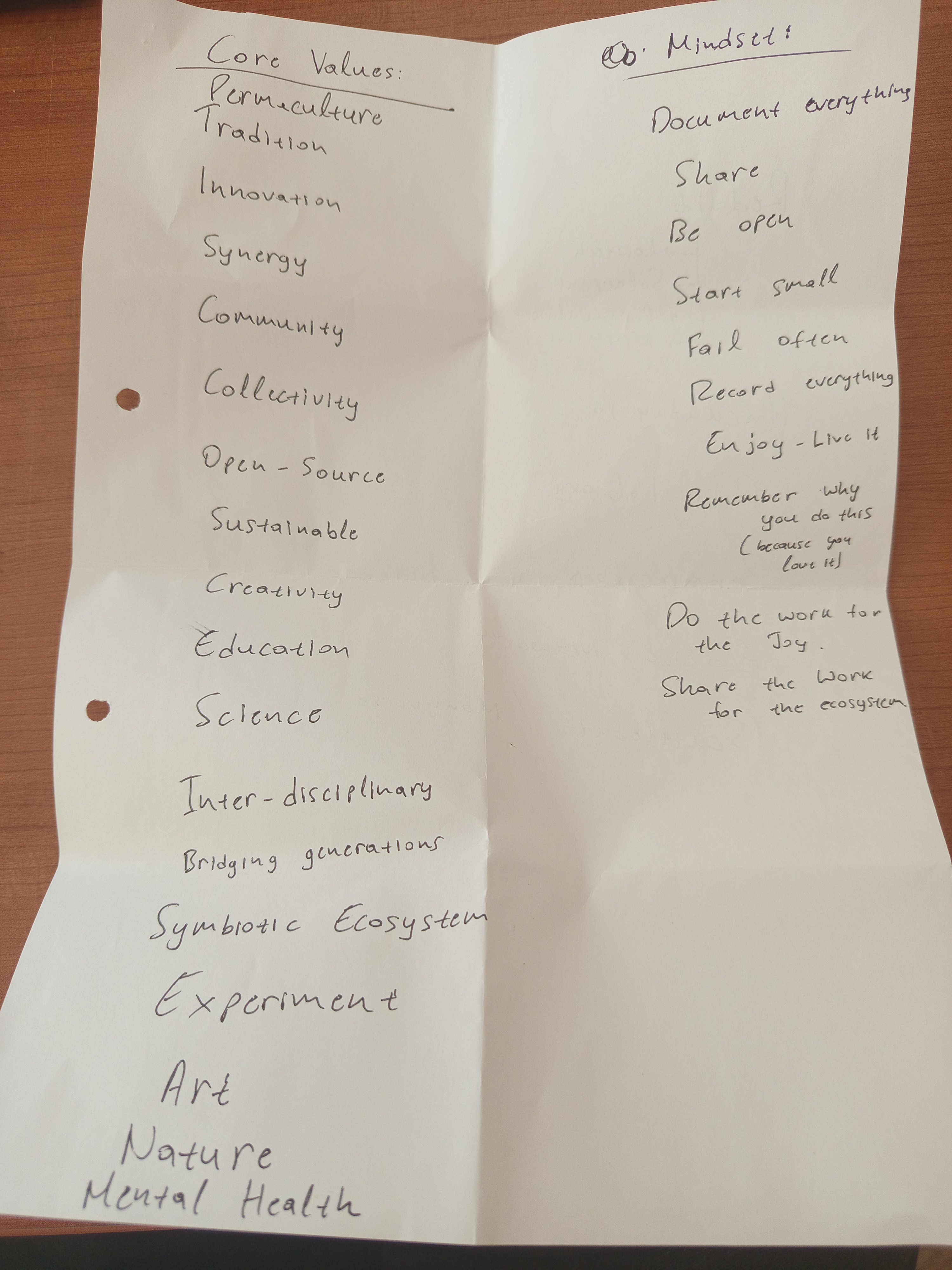
d) Making the vineyard resilient — a sustainable place that could survive a brutal, resource-scarce, post-apocalyptic world... like Bill and Frank’s sanctuary in The Last of UsAll of these visions excite me. But I’m not sure which one is the ultimate goal. What I do know is this: I have a few core values that will guide me through this unmapped journey. I’m writing them down here to serve as a compass for myself — and maybe, as a lighthouse for you, reader — in case something here speaks to you, and you want to walk a little of this road with me.
![]()
If any of these resonated with you, I can't wait to meet you and walk this road together.
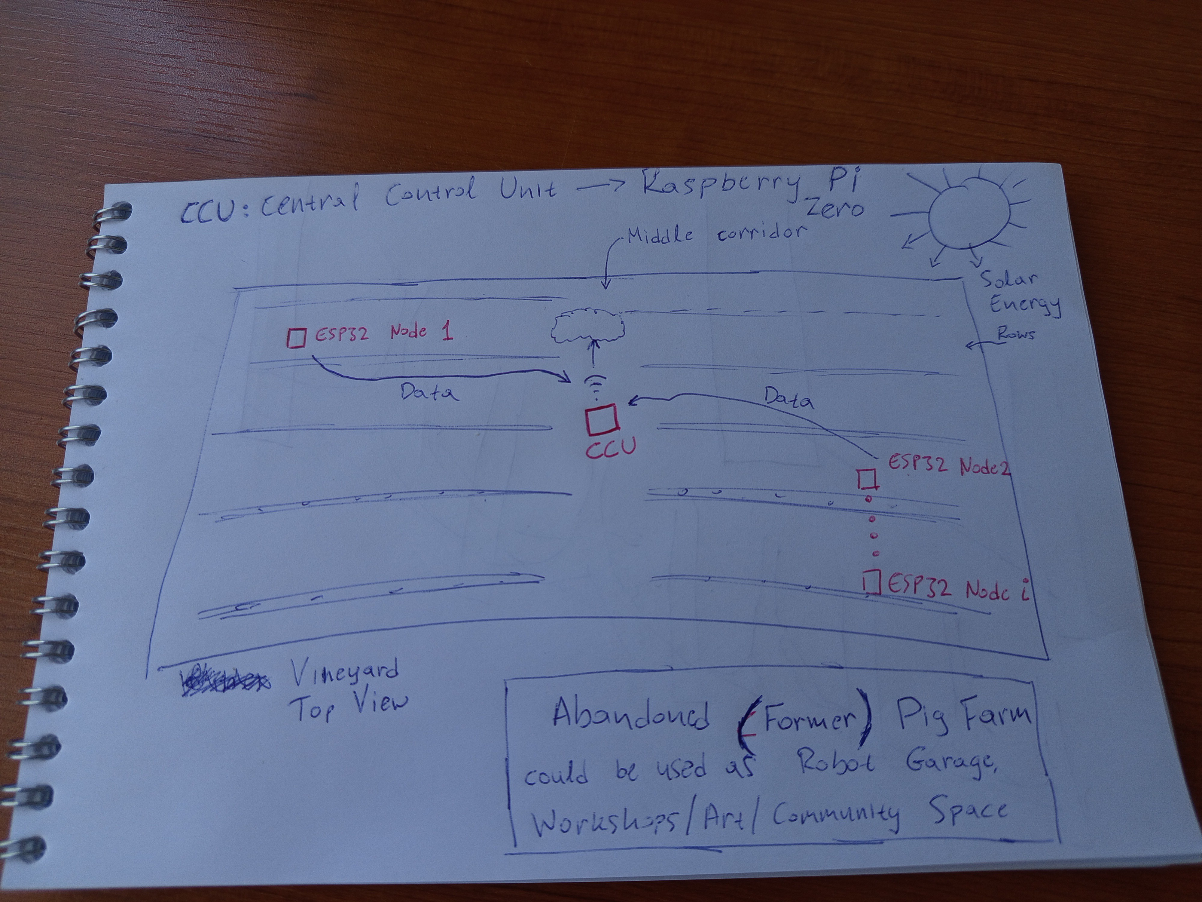
Let me show you how I imagine the vineyard:
![]()
As you can see there's a central control unit, a Raspberry pi zero 2w, which gathers data from distributed IoT sensors using ESP32 microcontrollers. As the vineyard is off-grid, both the Raspberry Pi and the ESP32s will be solar powered and will have battery for continuous operation. The raspberry pi may then be connected to the internet using cellular network (no WiFi available) to upload the data to a cloud database in order to monitor the vineyard from anywhere. If we manage to set this up, then sky is the limit. We could build a DIY mobile platform for fertilizing or monitoring of the vineyard. There's an abandoned pig farm nearby which we could use as a garage to park the robot safely. This could also serve as a multi-purpose area for events workshops etc etc...
But as in every ambitious plan, we need to take this step by step.
The project begins as an abstract idea, but it starts with buying some electronics, haha. Our rule is always one:
Buy the cheapest you can find!
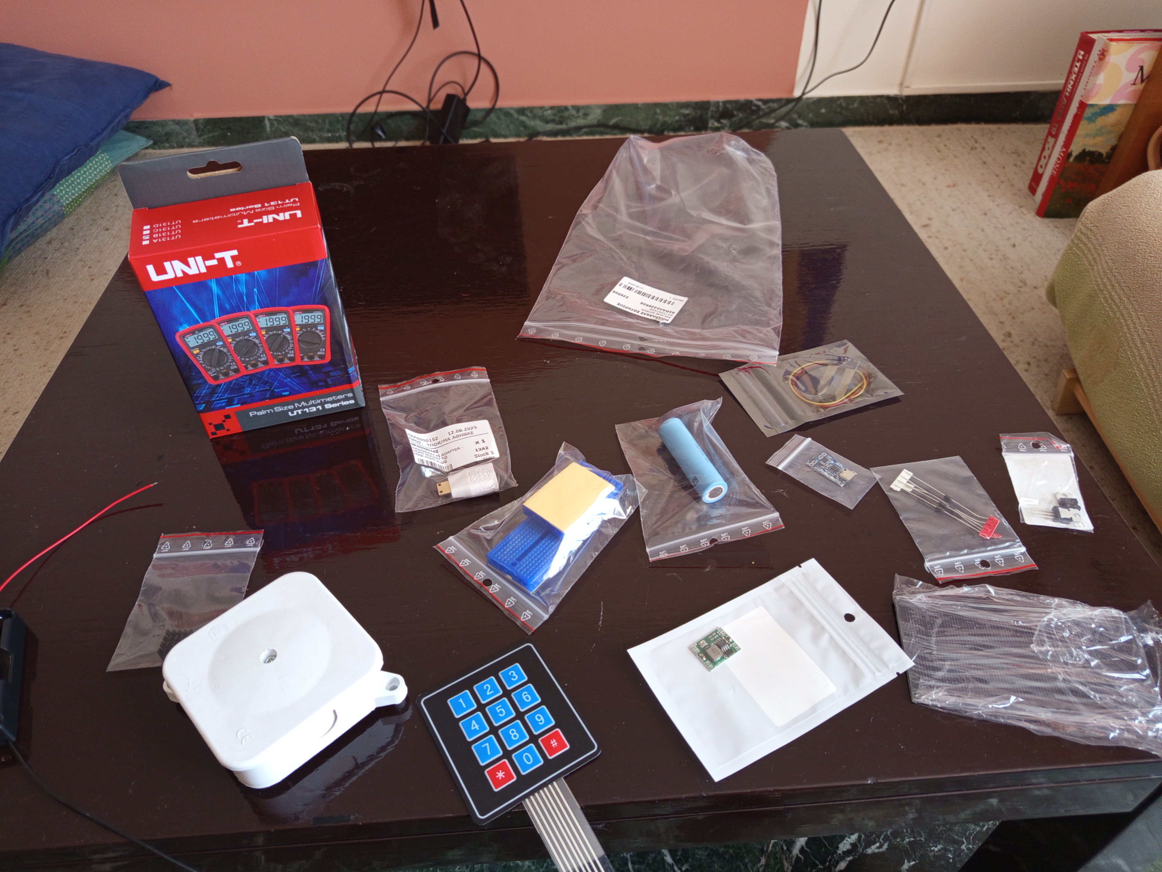
![]()
So, how do we begin?
I am thinking of two clear steps that require effort but will give us a lot of valuable knowledge and insights and really sky-rocket the project:
1) build and test a solar and battery powered esp32
2) build and test solar powered raspberry pi
The reason why we start with the esp32 is that it requires less power than the raspberry pi, which will be more challenging to power using sun.
Moreover, my experience with solar panel project is zero, so it will be a great chance to familiarise myself with that and learn from the problems that will definitely arise.
Stay tuned, and feel free to get in touch
An outdoor lab in our family vineyard
An experimental space for open DIY technology, sustainable agriculture, creative community, art, and connection between people and land