 retrobyte
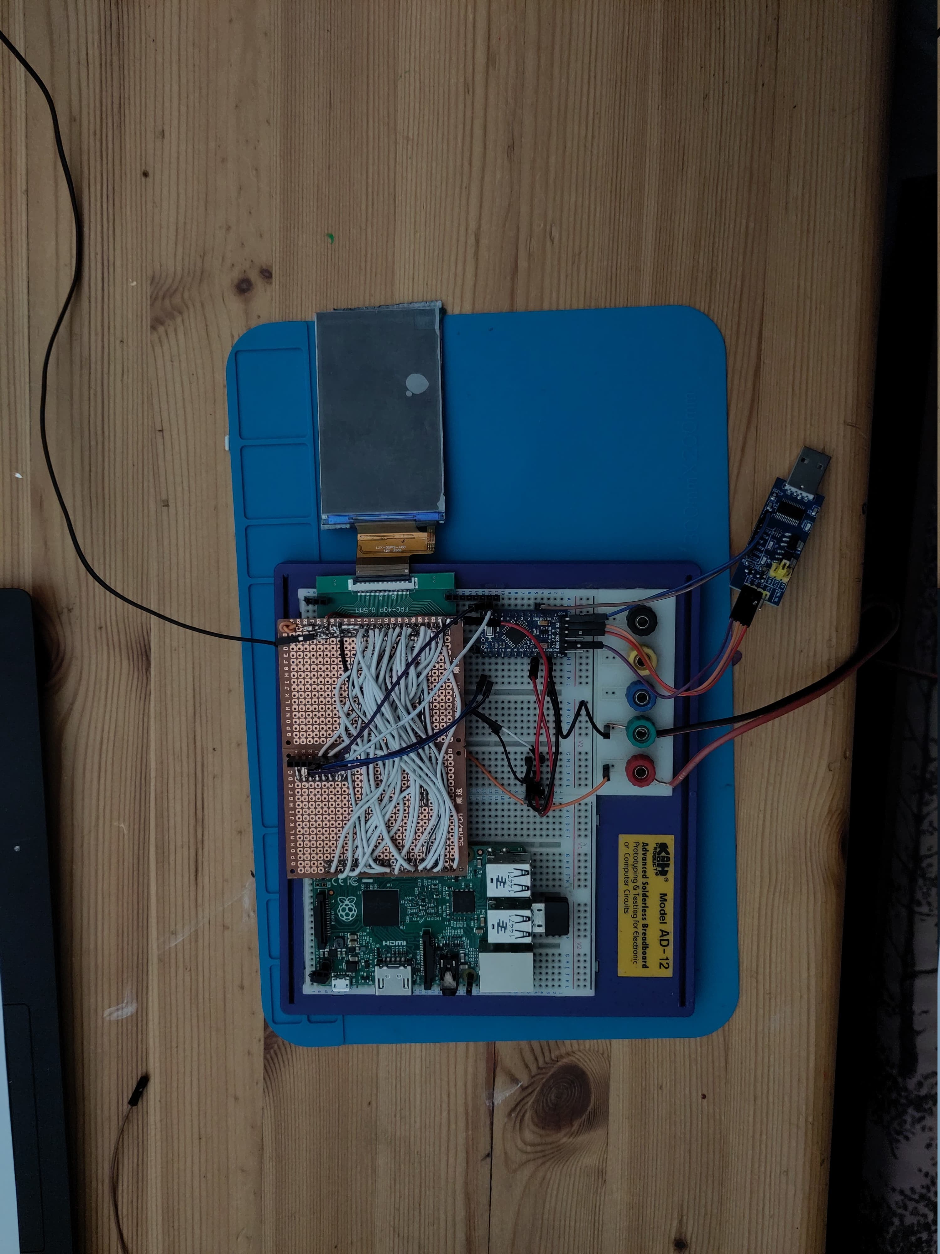
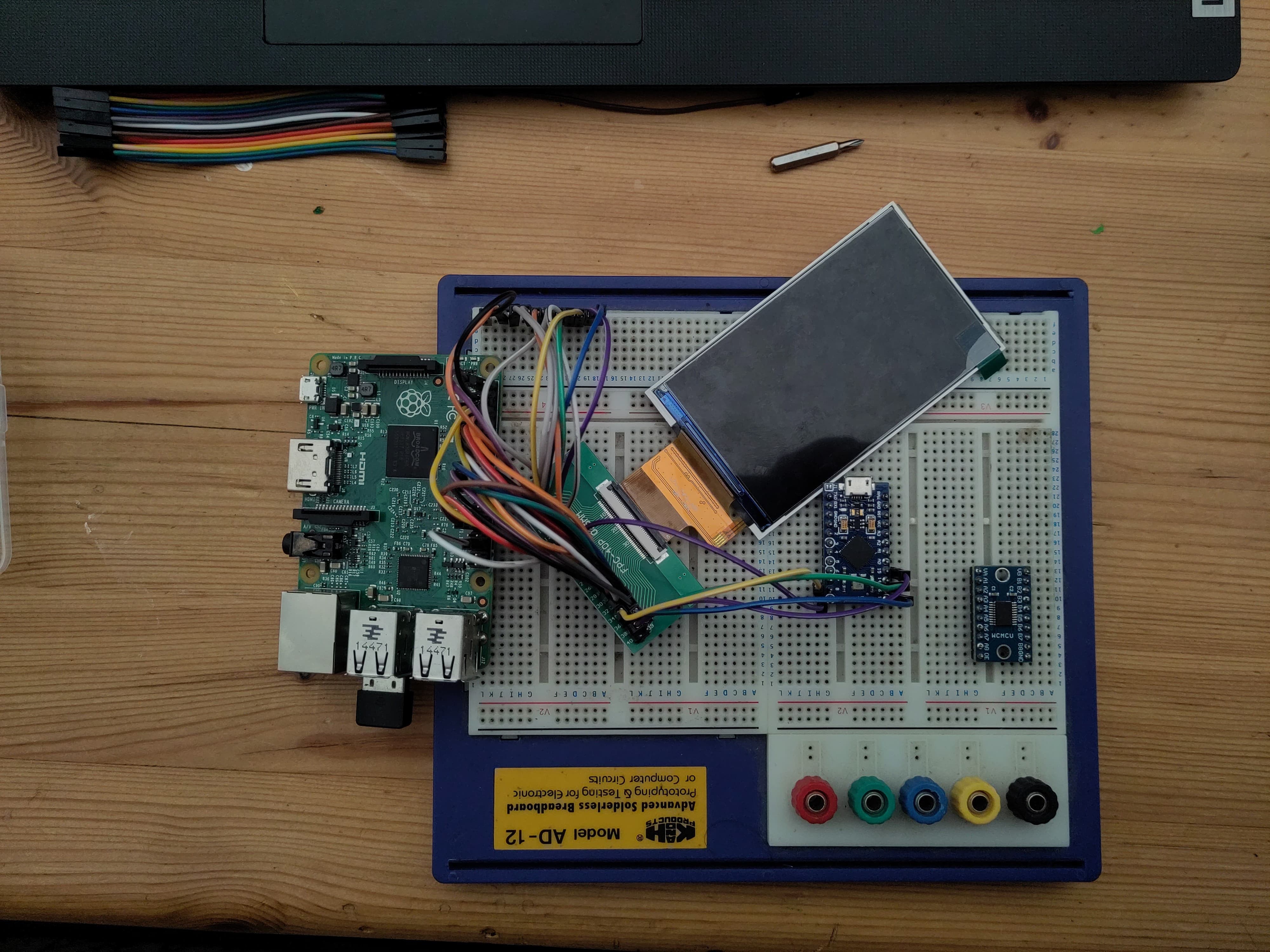
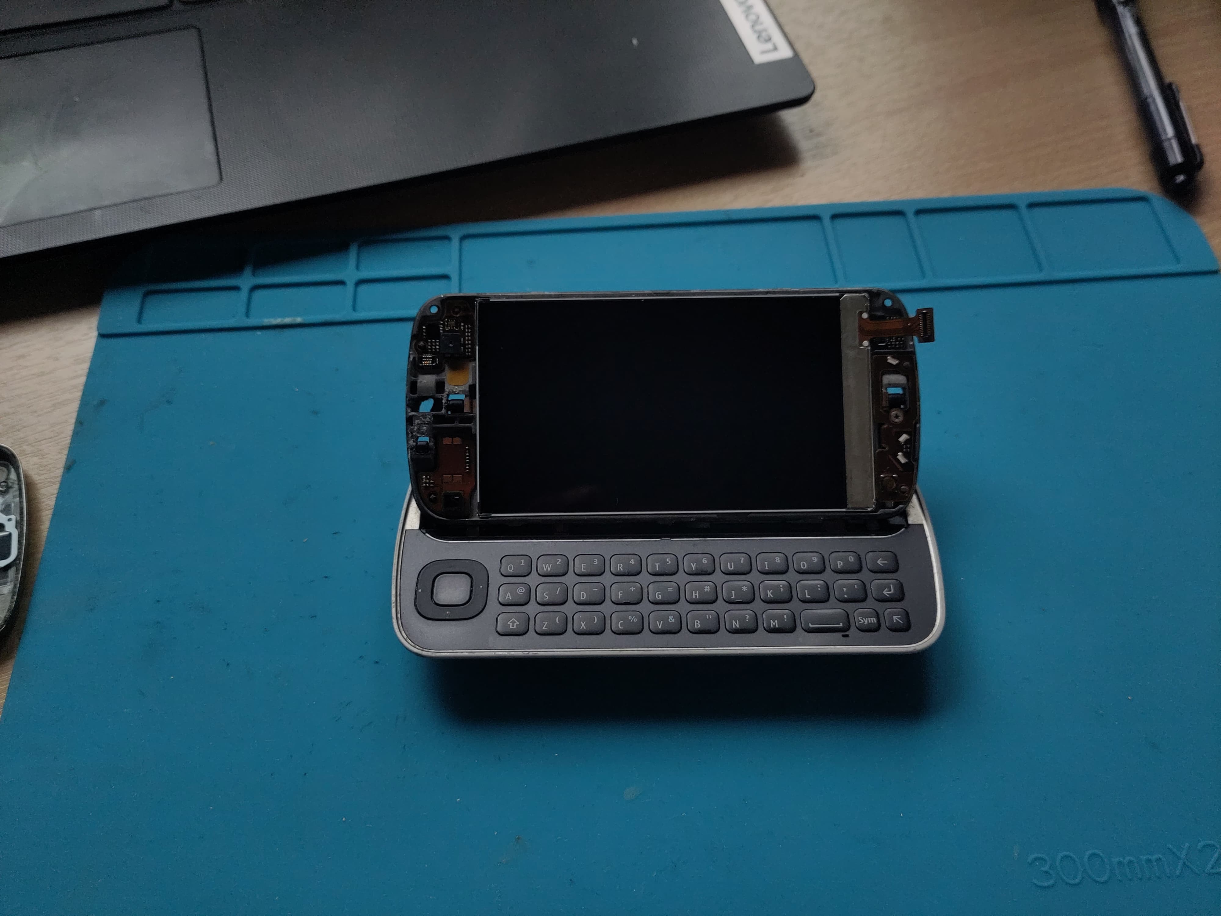
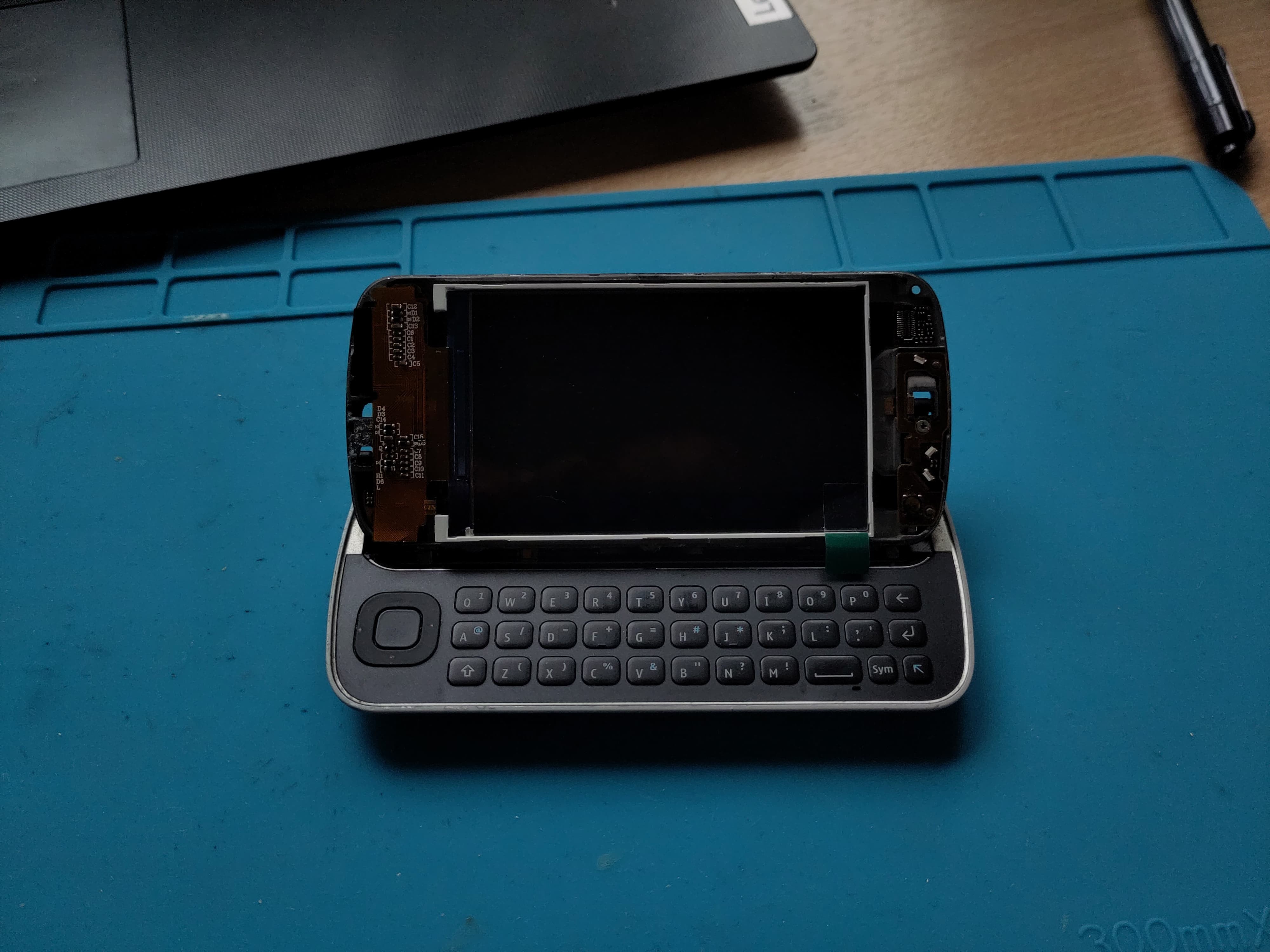
This project is focused on rebuilding a Nokia N97 into a functional Linux-based cyberdeck using a zero form factor SBC. Each part of the original phone is being reused or replaced with care to preserve the original look and feel while adding modern functionality.
🧠 Keyboard
-
Original Nokia N97 QWERTY slide-out keyboard
-
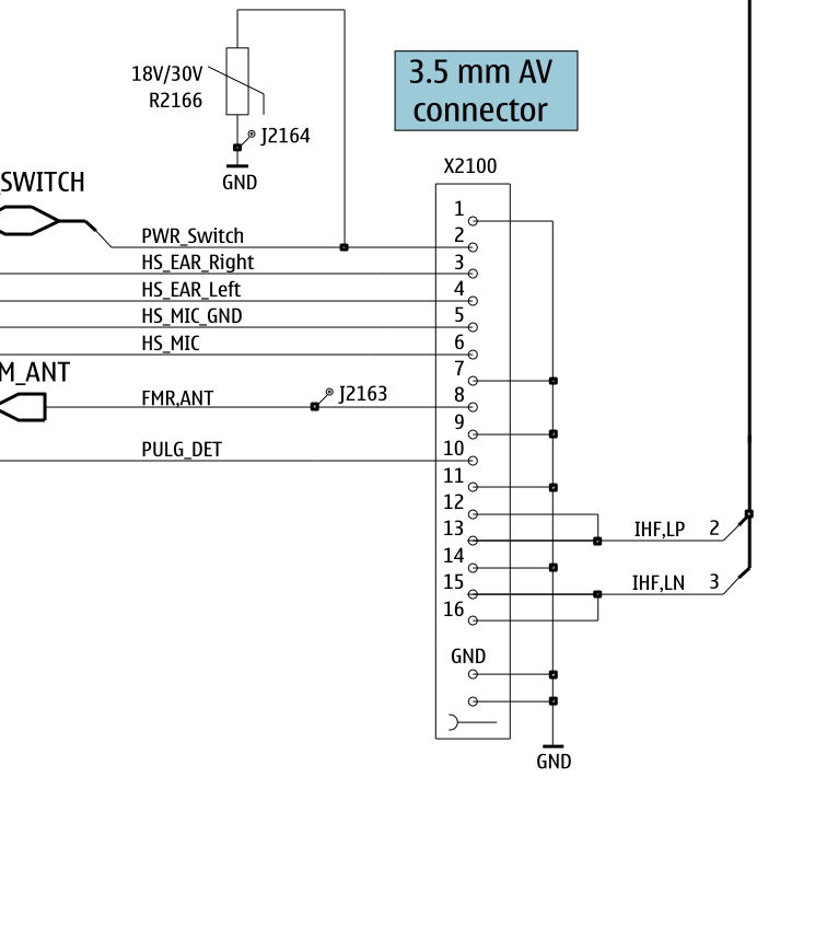
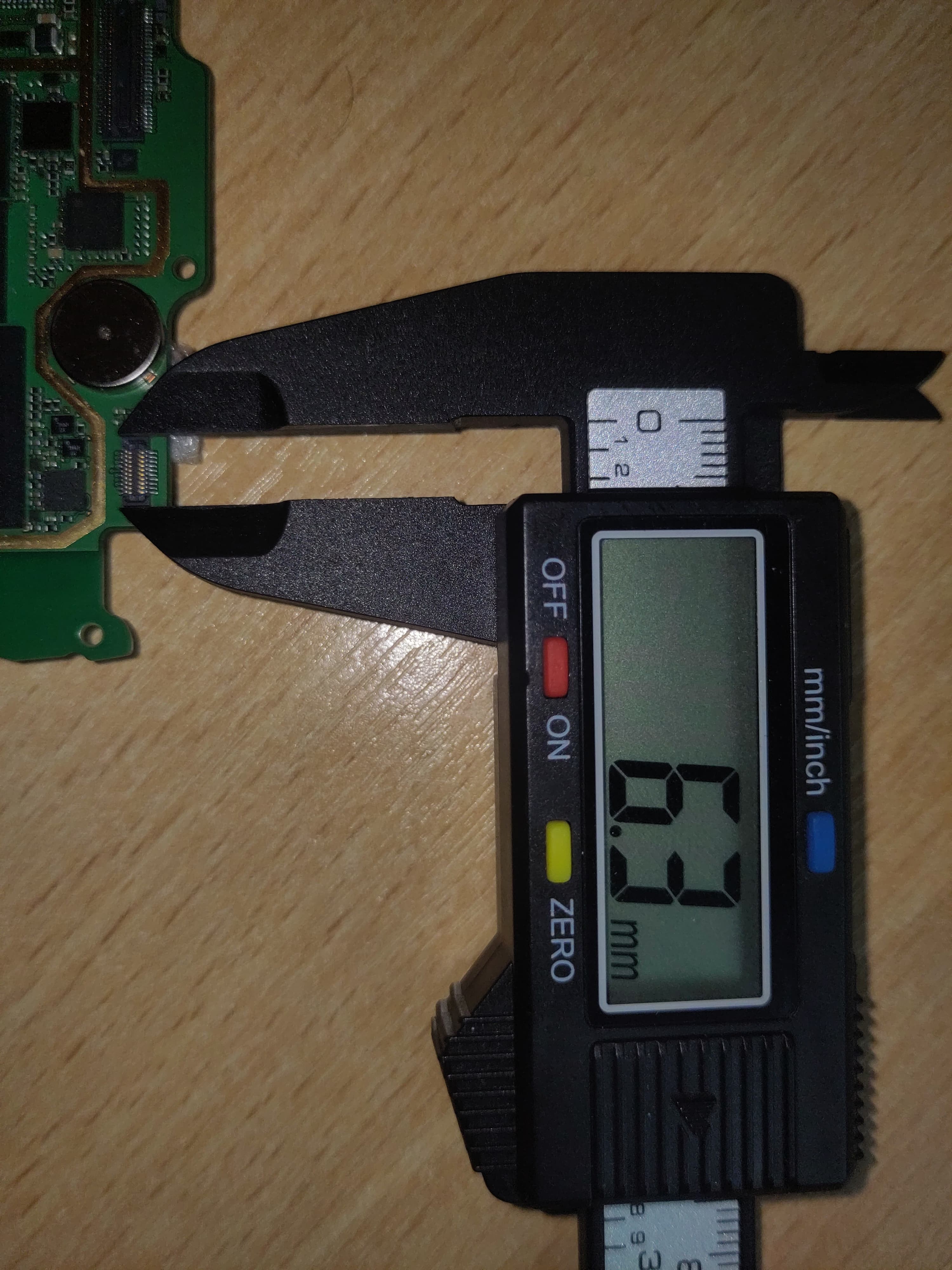
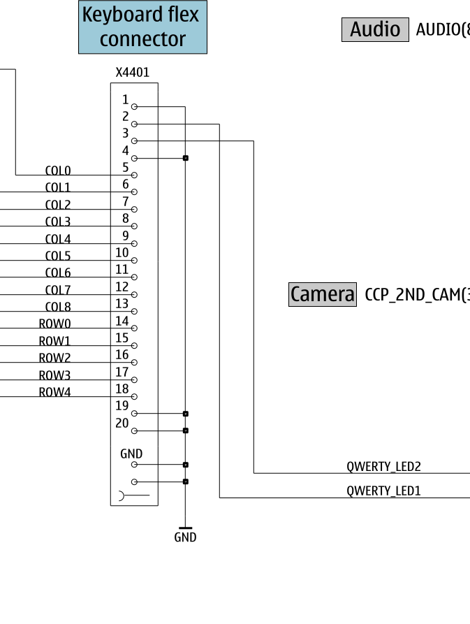
Connected via a 20-pin 0.4 mm pitch FPC (Hirose DF37NB-20DS-0.4V confirmed)
-
Logic level: 3.3 V, with 3.3 V backlight LEDs
-
Fully reverse-engineered using Nokia schematics
-
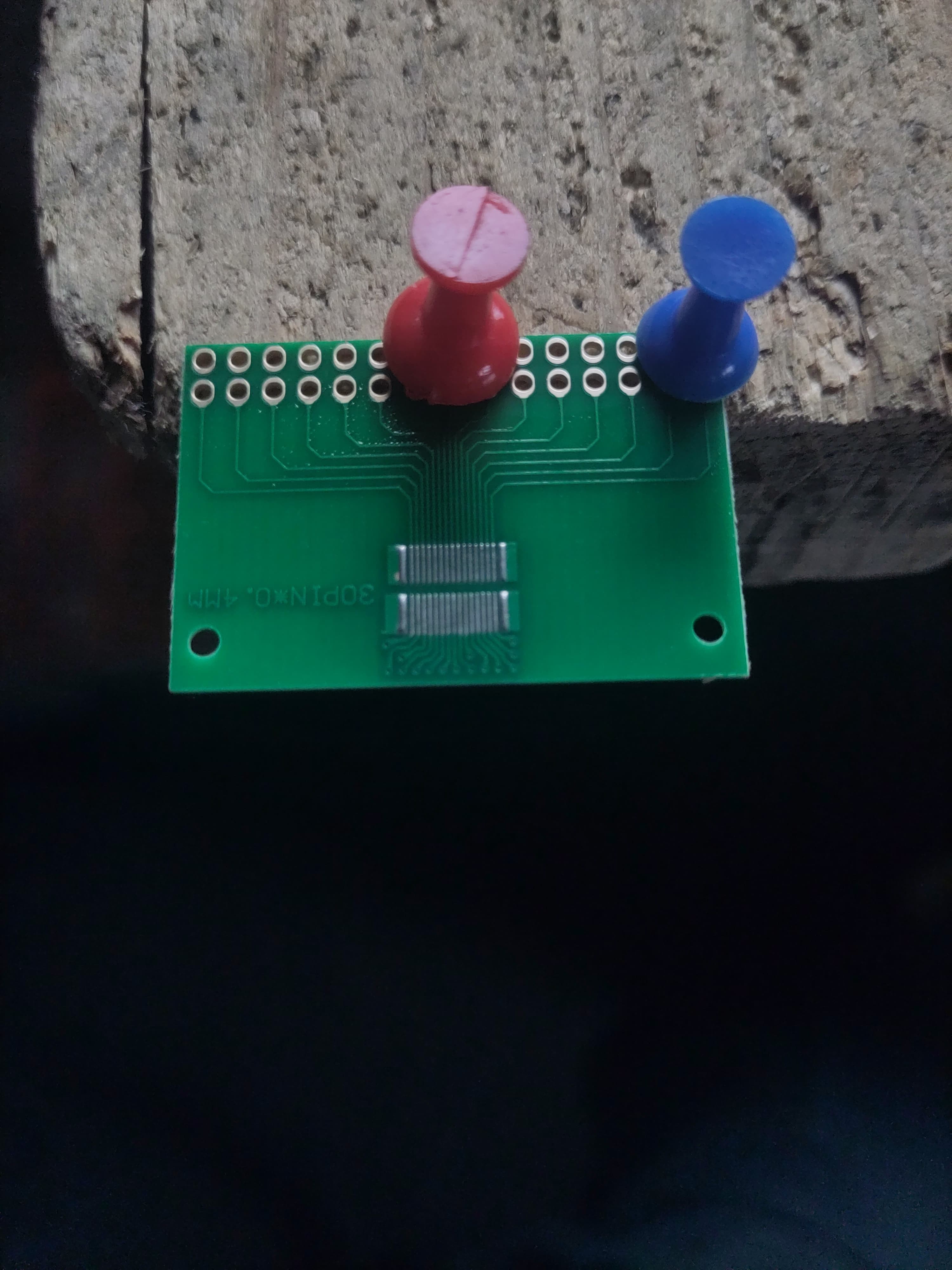
Custom breakout board designed and hand-soldered (0.4 mm pitch, no microscope)
-
Matrix scanning confirmed working on GPIO test rig
✋ Touchscreen
-
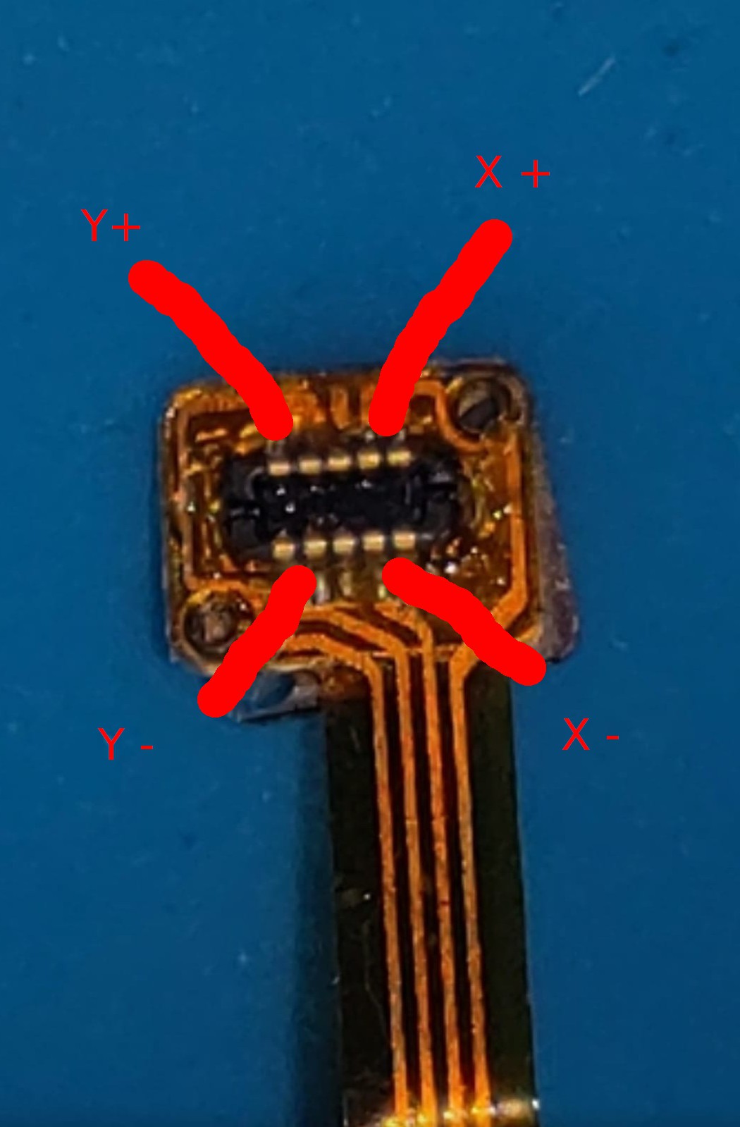
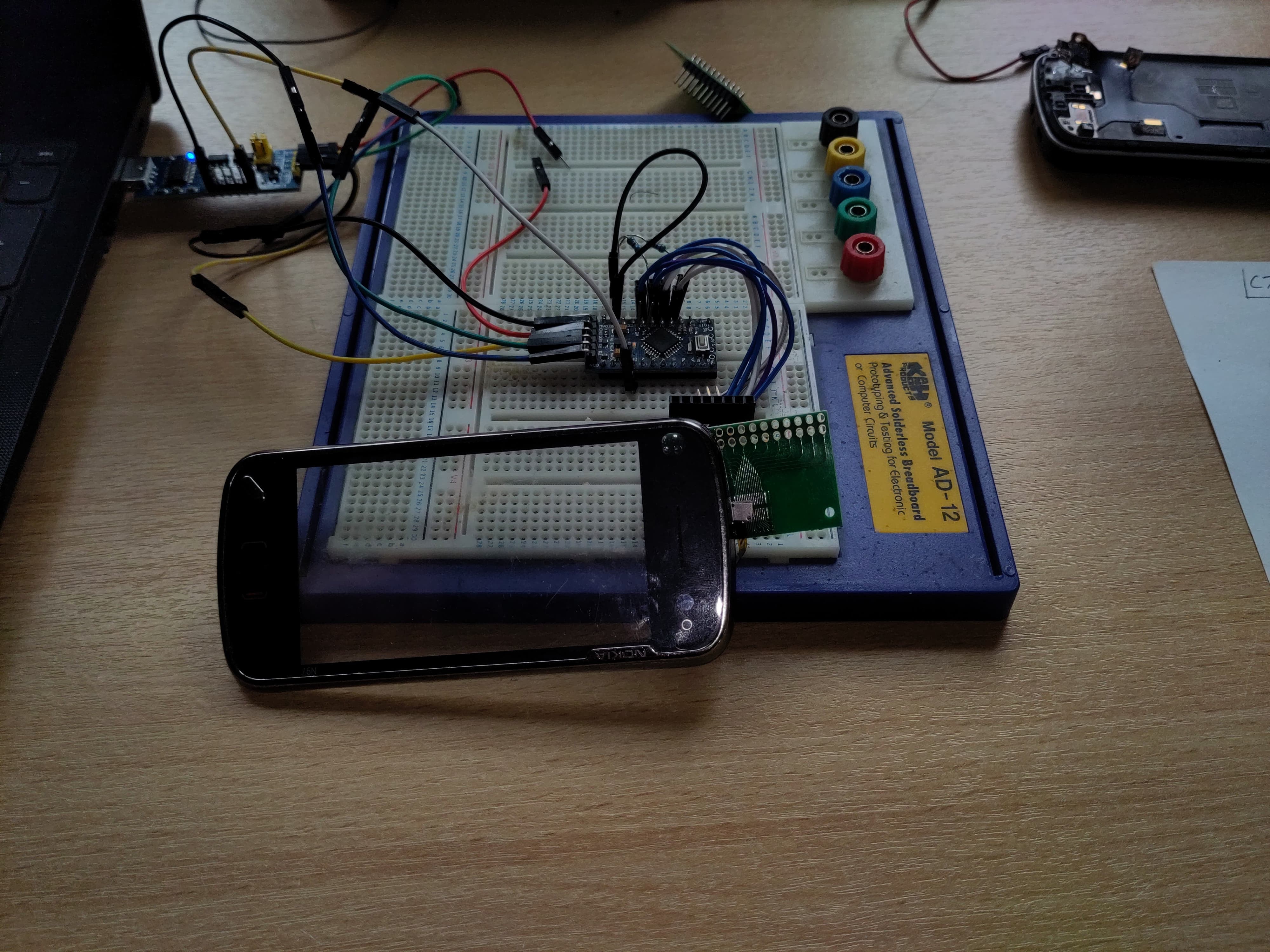
Original Nokia 4-wire resistive touchscreen
-
Verified by resistance probing (~600 Ω between X and Y axes)
-
No onboard controller — passive interface
-
Successfully tested using Arduino analog pins
-
Will be driven by an XPT2046 SPI controller on final board
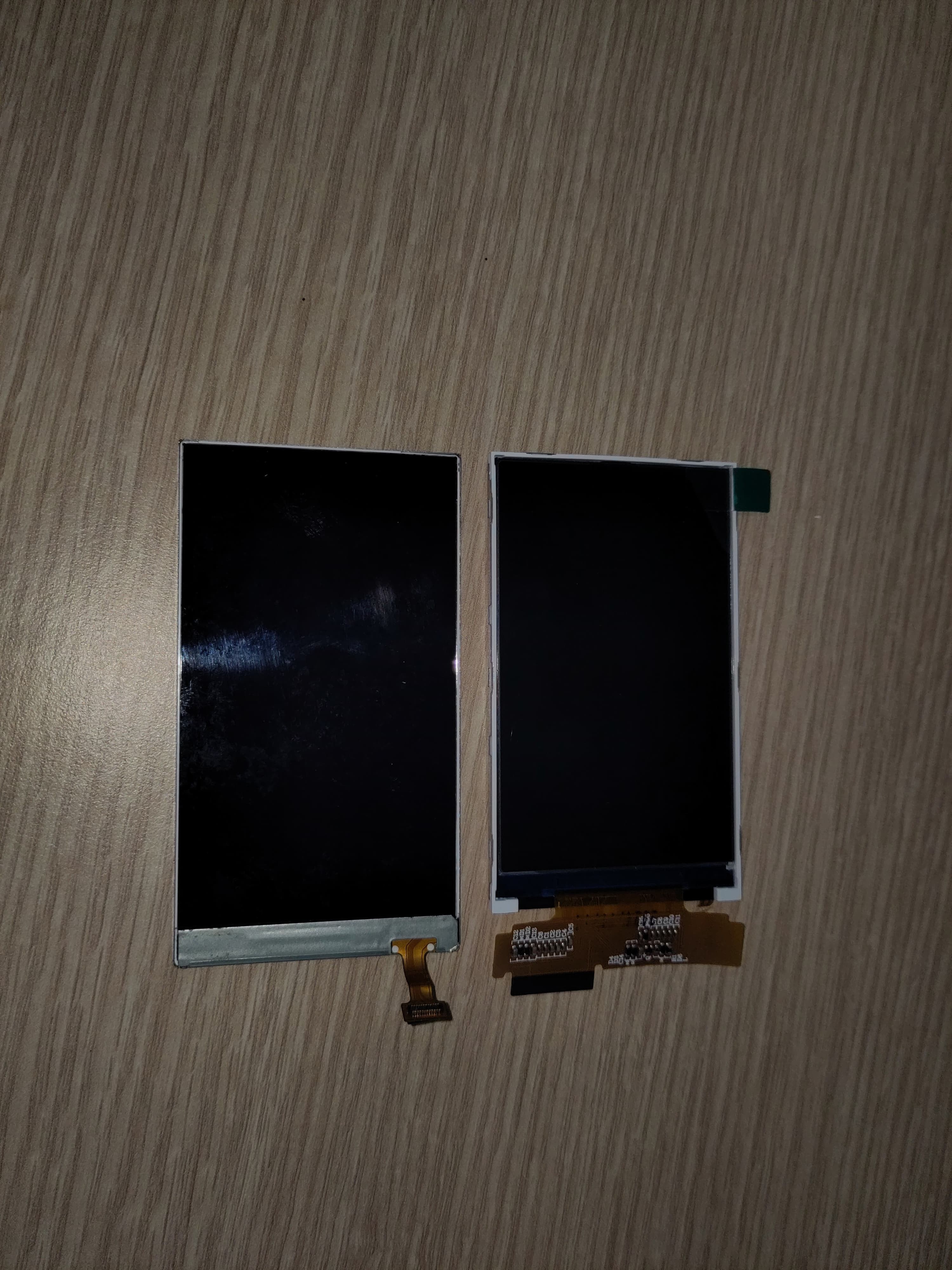
🖥 Display
-
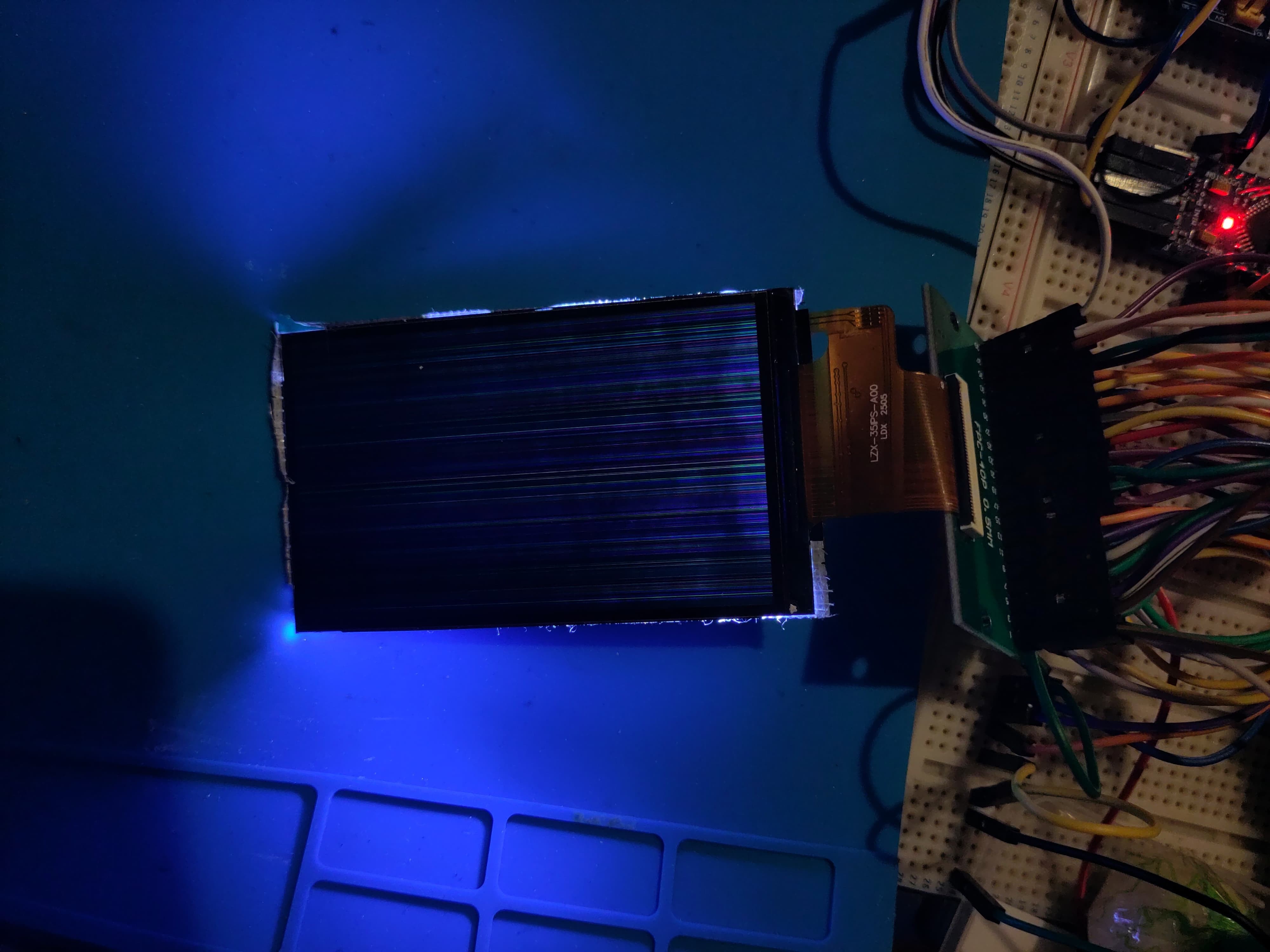
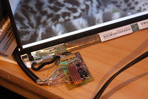
Original screen is RGB parallel (LTJ035L001A), but not Pi-compatible
-
Evaluating replacement with 3.2″ HDMI TFT panel (Waveshare or Inanbo)
-
Goal: high-resolution HDMI display within original bezel size
-
Plan to create custom HDMI board for clean internal integration
🔋 Power & Logic Board
-
3.7 V Li-ion cell as primary battery
-
MT3608 boost converter for 5 V
-
USB-C input for power + data (if space allows)
🔗 Connectors
-
FPC breakout for keyboard confirmed
-
Touchscreen connector re-used from original board
-
Backlight and GPIO routed via custom PCB (in progress)
-
All connectors will eventually be mounted to a single drop-in PCB for the N97 frame
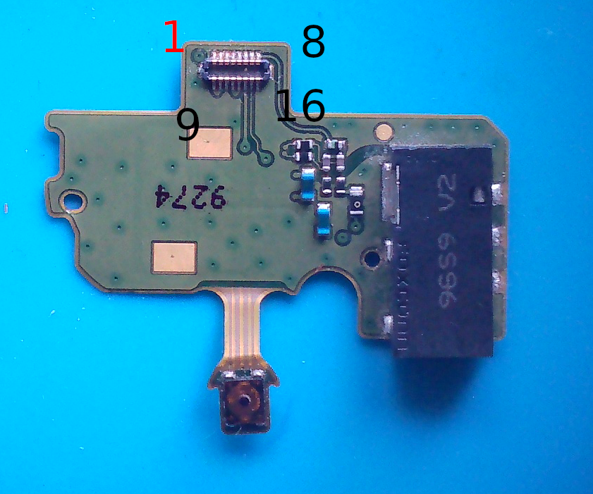
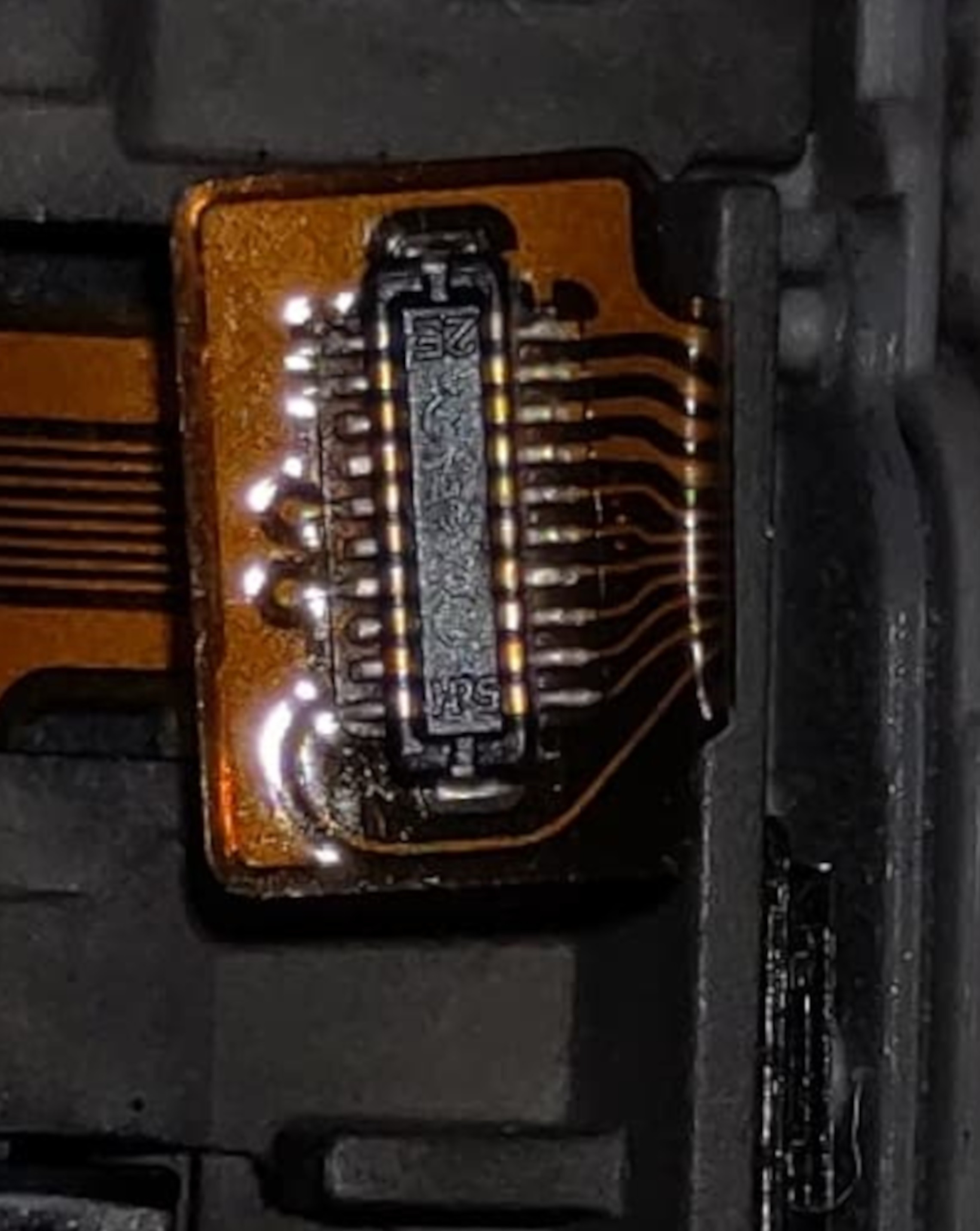
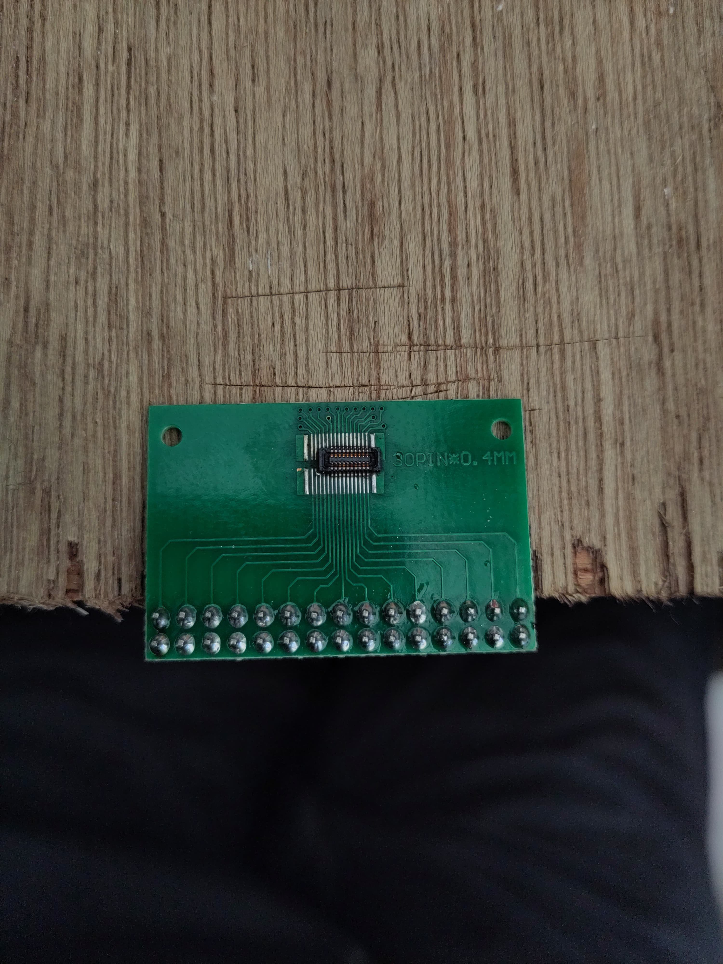 Salvaged and resoldered 20 pin FPC. No bridges on any of the FPC pins
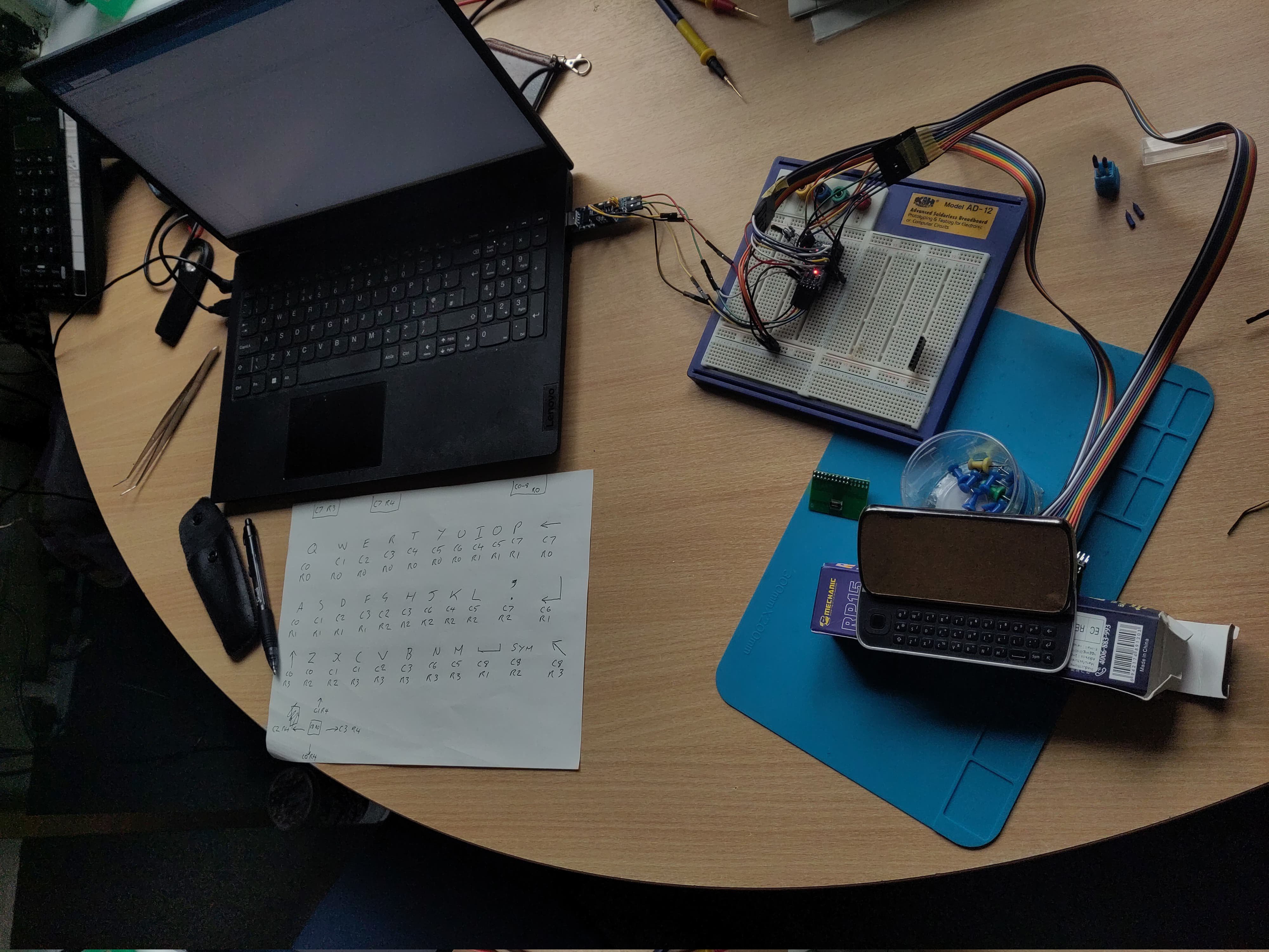
 Jared Sanson
 kmatch98
 Ben Combee
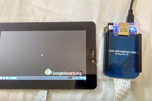
 Kumar, Abhishek