retrobyte
-
Project Update 9: Display Finally Responding—but Still a Blank Canvas
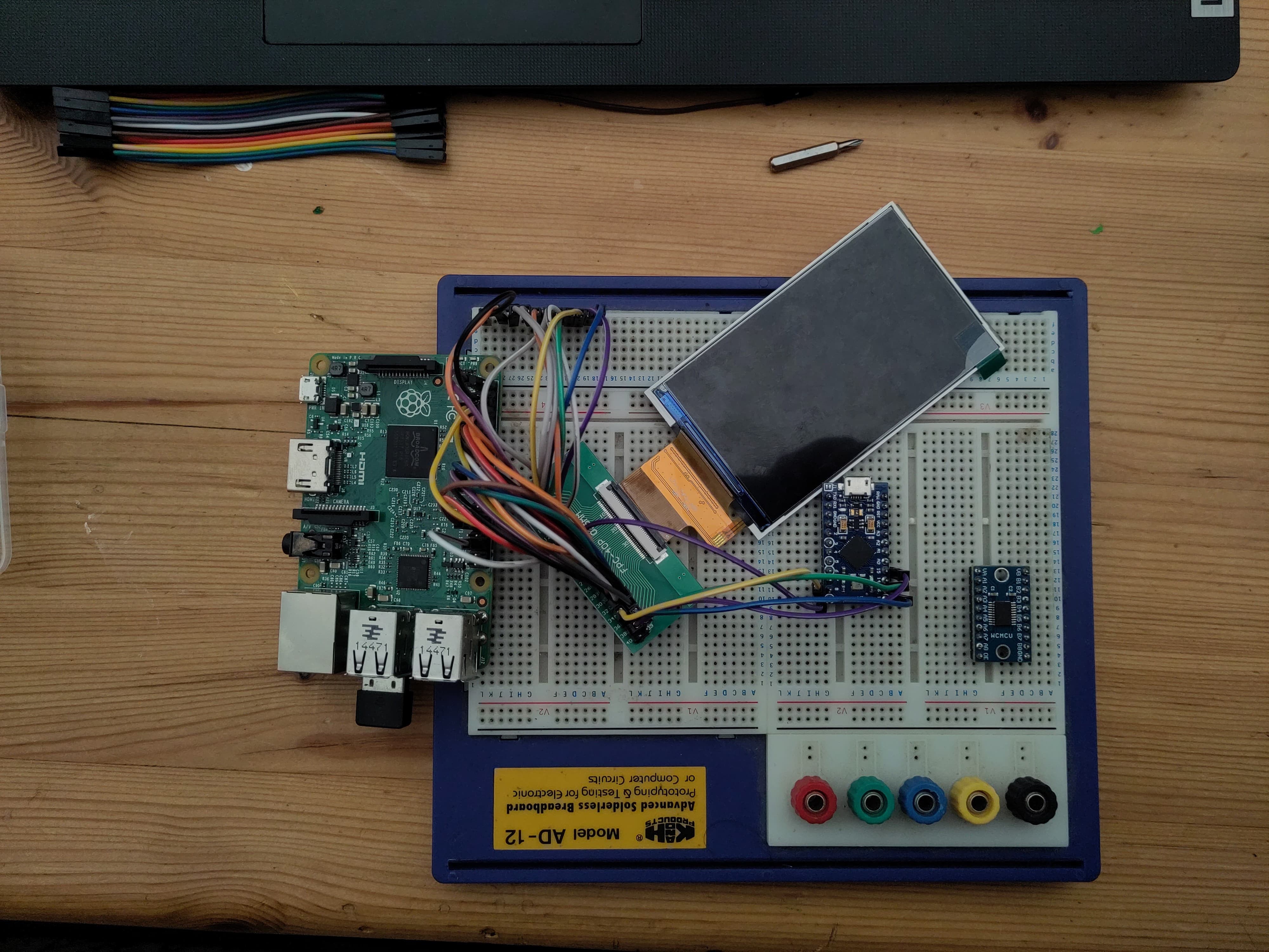
08/23/2025 at 19:35 • 0 commentsI finally got the replacement display to wake up and show actual colour output—but it’s only showing a vertical colour bar, not a full image yet. Still progress!
What’s Working
-
Display handshaking successful: After tweaking your initialization sequence, the screen now responds correctly—colour input is visible.
-
Registers are behaving: COLMOD, MADCTL and COLCTRL settings now register properly—colours (albeit limited) are appearing as expected.
That’s a big step over “nothing at all.”
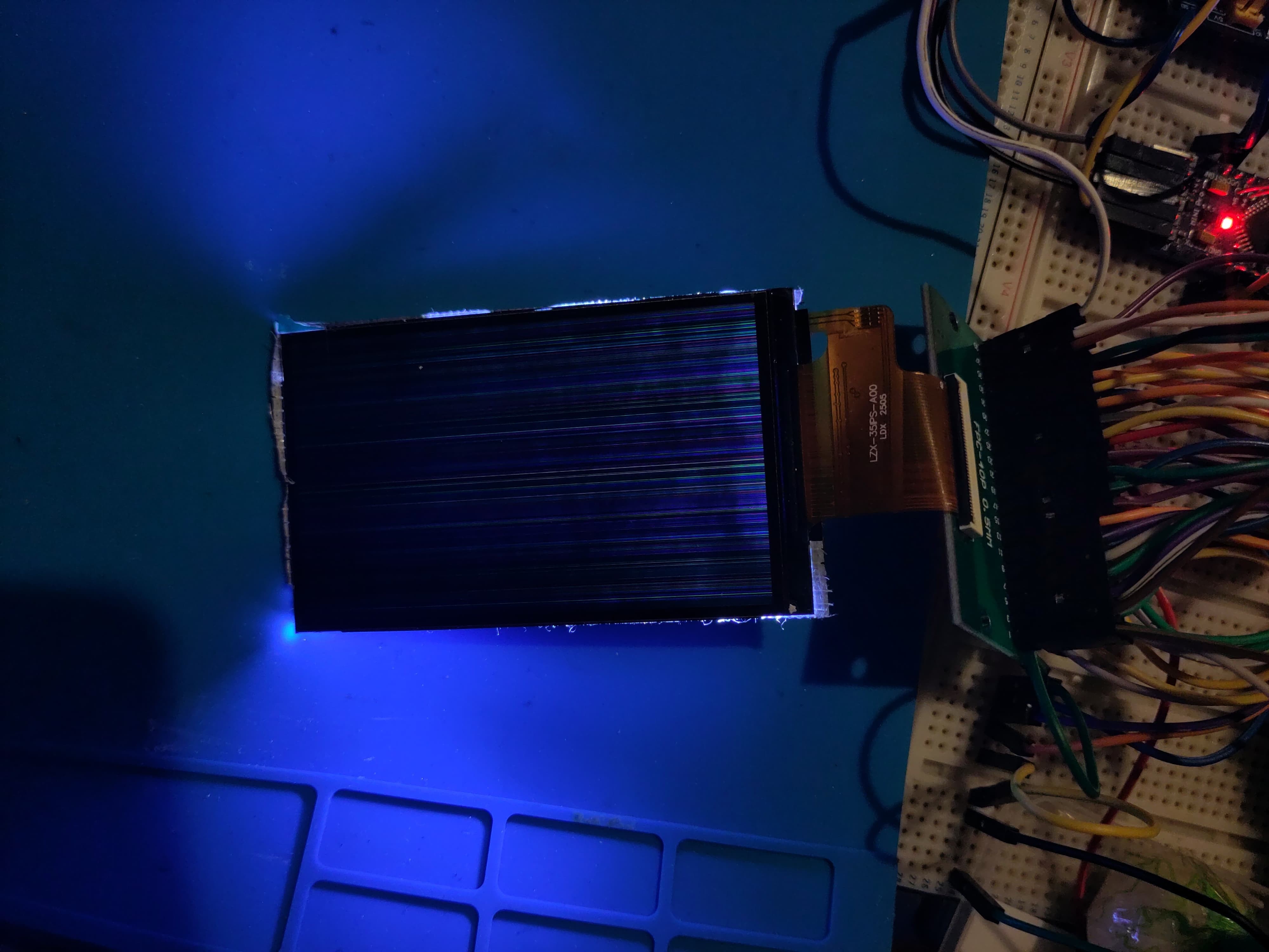
Current View: Just a Vertical Bar
Despite the screen lighting up, the output remains a vertical bar—static or shifting—but no actual framebuffer image is rendering.
This scenario typically points to one of two culprits:
-
Timing/synchronization mismatch—porch widths, active edge polarity, or sync pulses might still be slightly off.
-
Data bit misalignment or wiring error—only one set of colour bits (e.g., blue) is being correctly mapped, while red/green are getting lost or misinterpreted.
Next Steps on the To-Do List
Here’s the investigative roadmap I’m following to resolve it:
** 1. Double-check timing configuration** Align the Raspberry Pi’s DPI parameters (hfront / back-porch, hsync, vsync, pclk) against known working examples from similar screens
** 2. Revisit wiring and bus mapping** Ensure the display’s RGB lines are properly connected:
** 3. Explore differential init commands** Compare init sequence with any other similar panels that I can find, their may just be gold
link to frambuffer video
https://cdn.hackaday.io/files/2033918701880544/LCD_frame_buffer_responce_to_col.mp4
link to current semi working INIT
-
-
Project Log 8: RGB Issues and a New SBC
08/21/2025 at 12:07 • 0 commentsDisplay Framebuffer Activity — But No Meaningful Output Yet
I’ve made some solid progress with the RGB display on the Nokia N97 cyberdeck, but I’m still running into issues. The good news: the screen is showing framebuffer activity. That means the display is powered, initialized, and receiving pixel data. I can see coloured lines and flickers that confirm data is reaching the panel. However, the output isn’t yet meaningful — no clear image or UI is appearing.
This usually means the hardware communication is mostly working, but something is off in the initialization sequence or timing. It could be an incorrect reset pulse, bad signal polarity, or an issue with the framebuffer colour format. Debugging this is tricky, so I’ve been capturing video to document what’s happening and get feedback from the community.
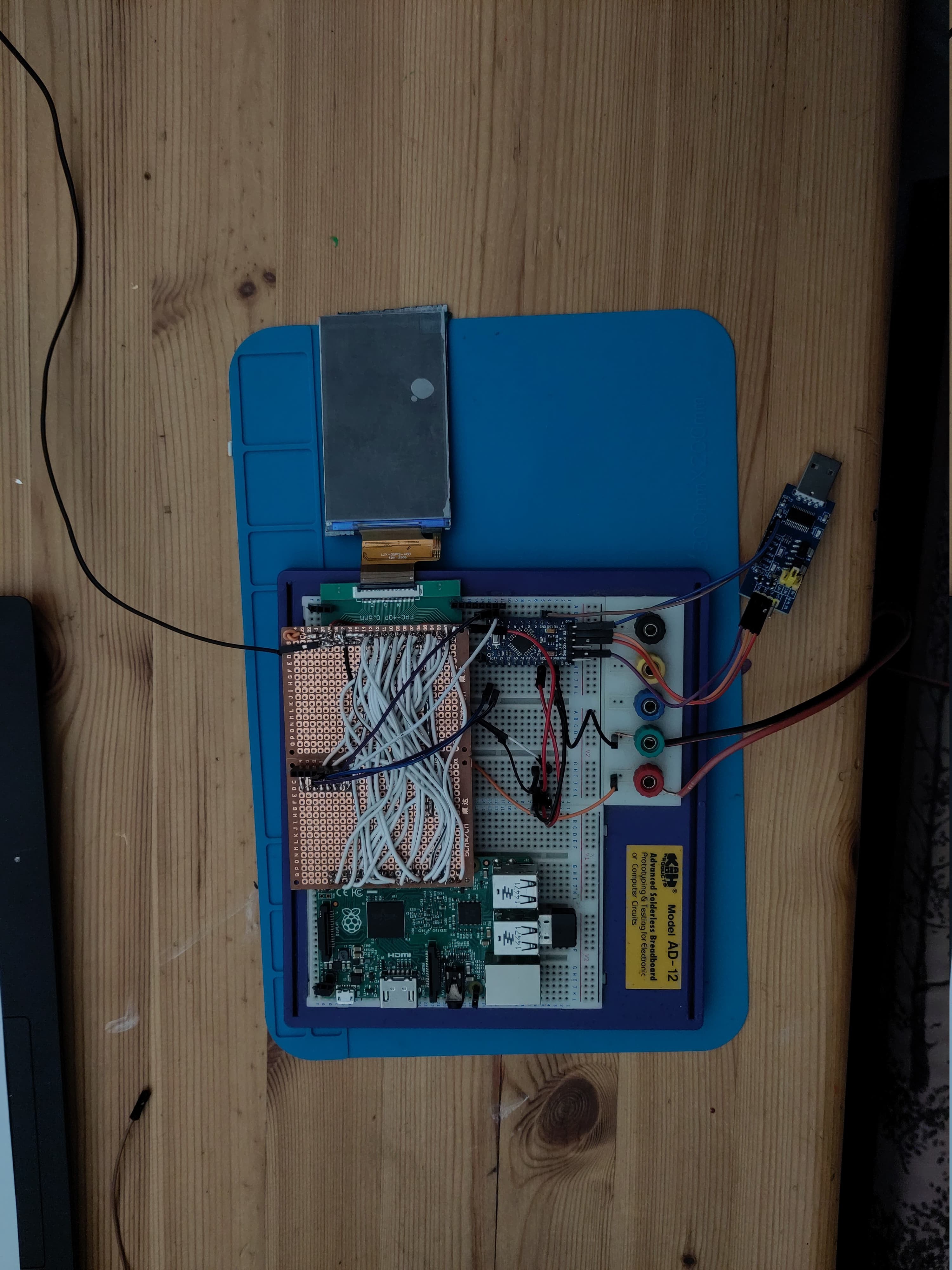
Prototyping on Full-Size Raspberry Pi, Moving to Compute Module 3+
For initial prototyping and testing, I used a full-size Raspberry Pi 3 Model B to quickly iterate on the display and software. Now that I’m moving closer to final integration, I’ve switched to the Raspberry Pi Compute Module 3+. The CM3+ offers a much smaller form factor and more flexible GPIO routing, making it a perfect fit for the cyberdeck’s compact chassis.
I’m updating the display initialization code and GPIO handling to match the Compute Module’s pinout, aiming to resolve the RGB panel communication issues and achieve a working display.
- link to screen video showing framebuffer activity.
- https://cdn.hackaday.io/files/2033918701880544/RGB_Framebuffer_active.mp4
-
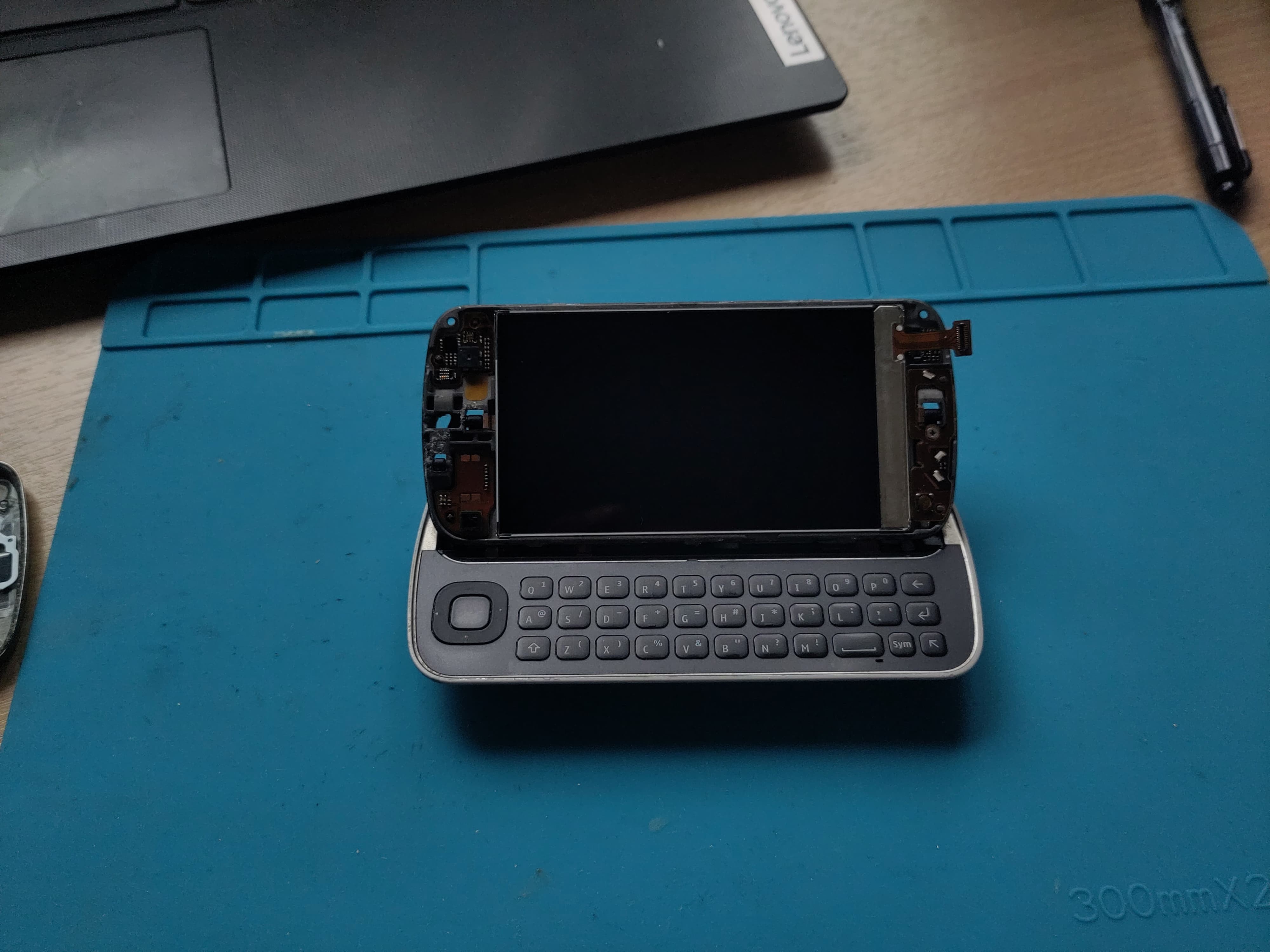
Project Log 7: LCD Testing Rig – Progress & a Painful Drop
07/31/2025 at 19:15 • 0 commentsSpent some time this week building and refining the test rig for the LCD panel. The goal was to get the RGB565-compatible display hooked up and talking to the SBC to start validating the interface. Wiring was less messy than dupont cables and things were going smoothly — power was stable, backlight was on, and I had all the signals mapped out.
Unfortunately… no image yet — and before I could get much deeper into debugging, I accidentally dropped the LCD and cracked it. 💀
Not ideal, obviously. But I’m posting this as part of the "real build log" — mistakes and setbacks are part of the process. I’ve got a replacement screen already on order, and I’ll be taking a closer look at the signal integrity and timing once it arrives. This time, I’ll be securing the panel to the jig before powering on.
The upside:
-
The test rig layout itself works
-
GPIO/pin mapping seems solid
-
I now know exactly how fragile this panel is 😅
More soon once the new screen arrives. If anyone’s got tips on minimizing LCD signal noise or working with RGB565 over FPC, I’m all ears.
![]()
-
-
Project Log 6 Its alive ish
07/25/2025 at 18:10 • 0 commentsUpdate: Screen Initialisation and Frame buffer Output
Great news! The Nokia N97’s screen is now initializing correctly, and I’m beginning to see framebuffer output on the display.
The attached photo shows RGB color lines rendered on the screen — a clear sign that the display controller is receiving and showing pixel data as expected. This means the screen initialization sequence and framebuffer communication are working well.
This is a significant step forward in resurrecting the N97’s display for the cyberdeck build. Next up, I’ll focus on refining the graphics output.
Stay tuned for more progress!
![]()
-
Project Log 5 – New Display
07/23/2025 at 22:19 • 0 commentsSwapped out the previous display for a D350N1013V1 — it’s a much better physical fit for the cyberdeck layout and supports RGB565 over 3-wire SPI, which keeps things tidy.
Unfortunately, no signs of life yet.
I’ve verified that the Raspberry Pi is sending the initialization commands (sniffed with a logic analyzer), and power seems good, but the display doesn’t turn on or respond at all — no flicker, no backlight, nothing. It feels like something in the init sequence or timing isn’t quite right, but I could be overlooking something obvious.
If anyone’s worked with this panel (or similar SPI RGB displays), I’d really appreciate a second set of eyes. Ideas, example init sequences, or even a “you forgot the reset pin” would be welcome!
📄 D350N1013V1 Datasheet (ZIP)
🧪 Current init test code (INO)Appreciate any thoughts
![]()
-
Project Log #4 – Headphone Jack and Power Button FPC Pinout
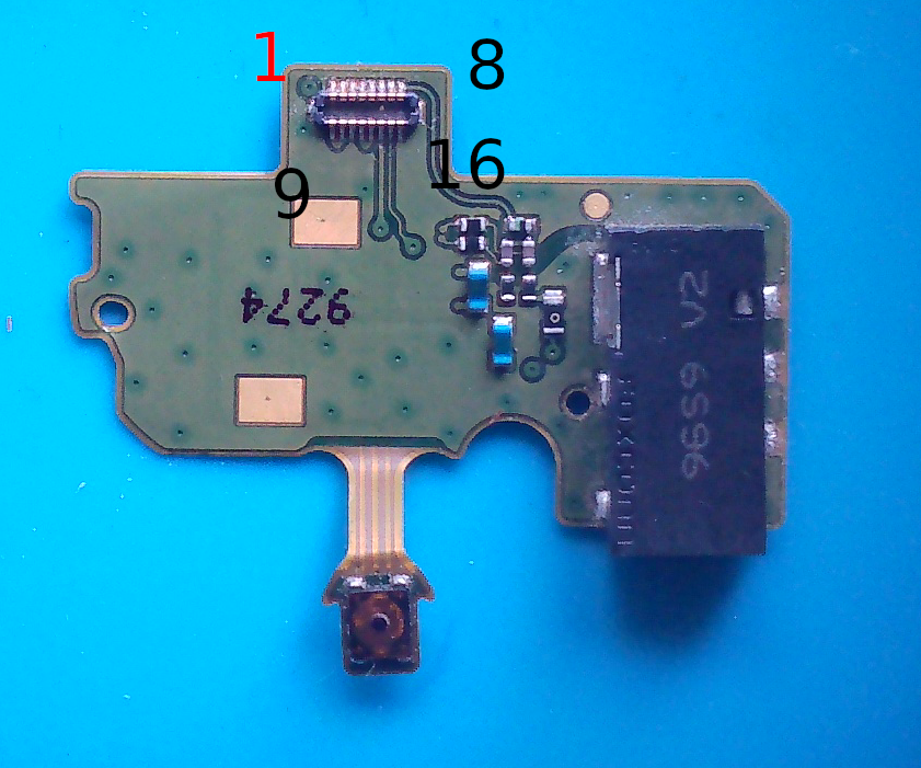
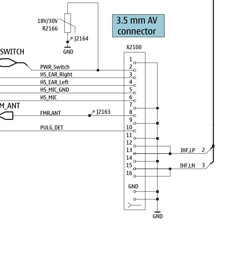
07/02/2025 at 18:20 • 0 commentsNot a huge update, but a meaningful one: I spent some time tracing out the pinout for the headphone jack and power button FPC (the small sub-board that originally plugged into the N97's main PCB).
Since this is a cyberdeck from 2009, it obviously needs a headphone jack. 😎
Plus, having a physical power button is going to make the build feel a lot more finished and usable.Using continuity testing and a bit of guesswork from the schematics, I’ve mapped:
-
The 3.5mm jack left/right/ground
-
The momentary switch used for power (which I'll use as a shutdown or wake GPIO trigger)
I'll connect this sub-board directly to the Pi’s GPIO header and 3.3 V audio out, or possibly route through a small amp if needed. The button will go to a GPIO with a pull-up + debounce.
![]()
![]()
-
-
Project Log #3 – Choosing a Display: Original vs. HDMI
06/28/2025 at 11:34 • 0 commentsThis update focuses on the most visual part of the cyberdeck: the screen.
The Nokia N97 originally used a TPO LTJ035L001A panel — a 3.5″ RGB interface TFT with no onboard controller. It connected via an FPC ribbon to the mainboard through the X4400 connector. While functional in its time, it’s not Pi-friendly: it lacks HDMI, SPI, or even I²C, and needs a parallel RGB driver (or something like an RTD2660H).
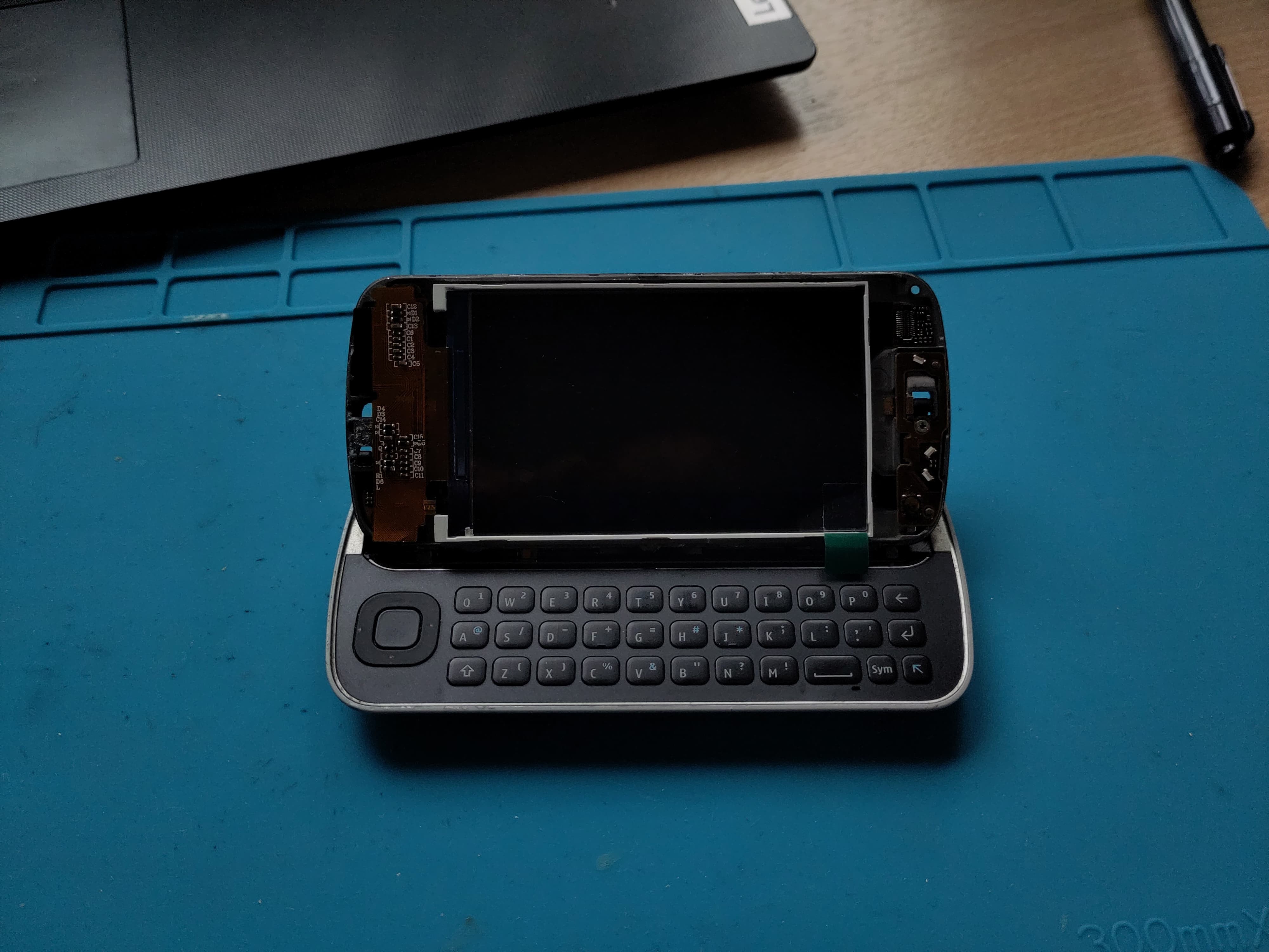
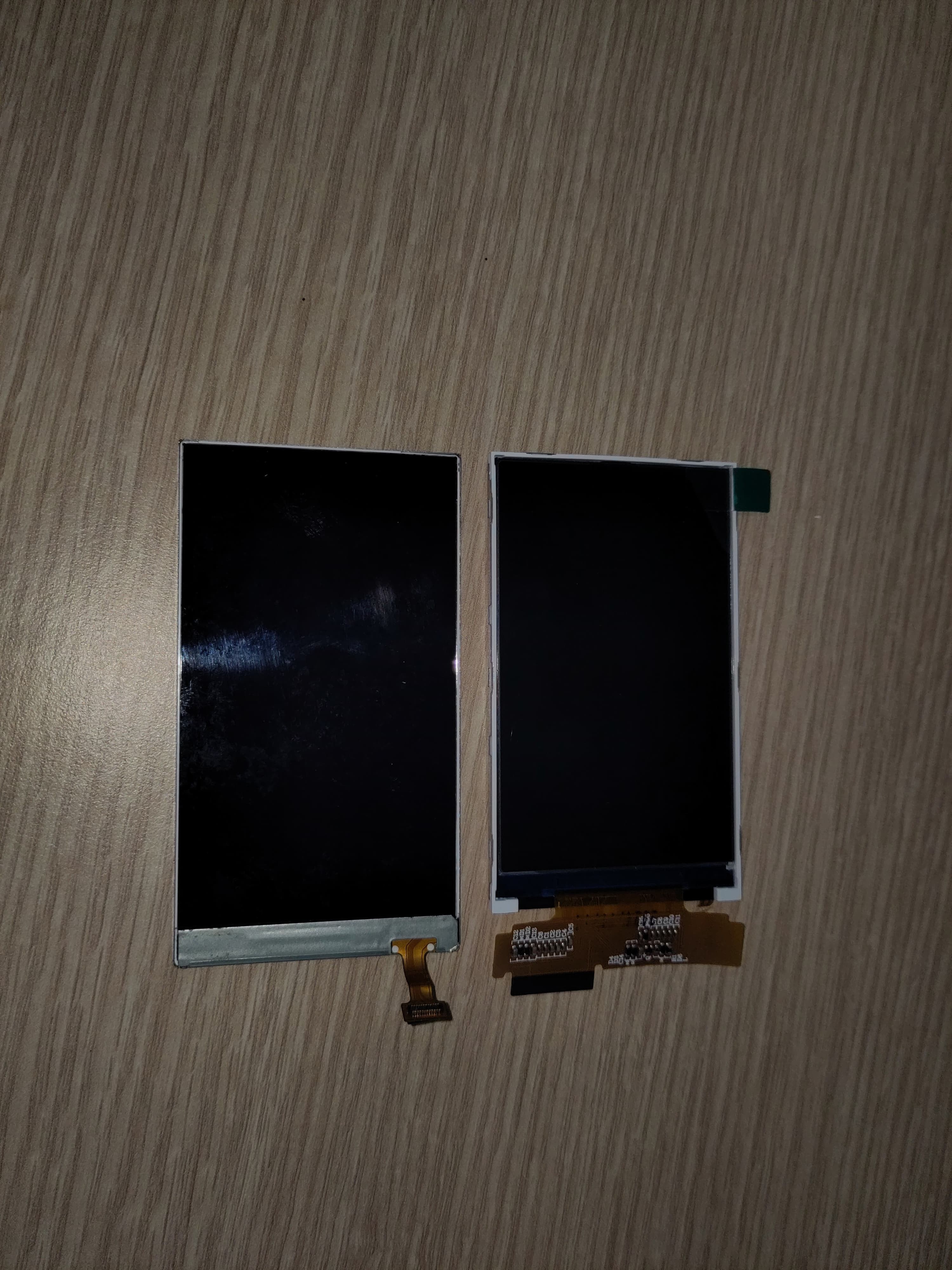
📸 Size Matters: Comparing Original vs. HDMI
I’ve been testing a 3.2″ HDMI TFT panel (Waveshare / Inanbo) as a replacement. I’ve included comparison shots of:
-
The original Nokia display next to the HDMI panel
-
Both displays in the N97 frame for visual reference
Surprisingly, the new display is almost a perfect mechanical fit — slightly smaller in width, which helps with routing, and thin enough to slide into the original mounting location with minimal modification.
✅ Why HDMI Wins
-
Easy Pi compatibility: True plug-and-play, no controller needed
-
Higher resolution (800×480 or better
-
Will work with a custom low-profile driver board, which I plan to integrate into the main PCB
🔧 Notes
-
Original display flex pinout is undocumented and not standard RGB
-
I still plan to reuse the touchscreen from the original assembly (tested and working)
-
Backlight wiring for the HDMI panel will be adapted to fit the N97 battery and boost converter setup
🛠 Next Up
-
Start building the HDMI display support into the PCB layout
-
Design the mounting system (clips or frame supports) to hold the display in place under the slider
-
Route power, backlight, and touchscreen interface into the same board
![]()
Original LCD
![]()
Inanbo t32chrip51 v19
![]()
Original Left replacement Right
-
-
Project Log #2 – Touchscreen Testing and FPC Connector Identification
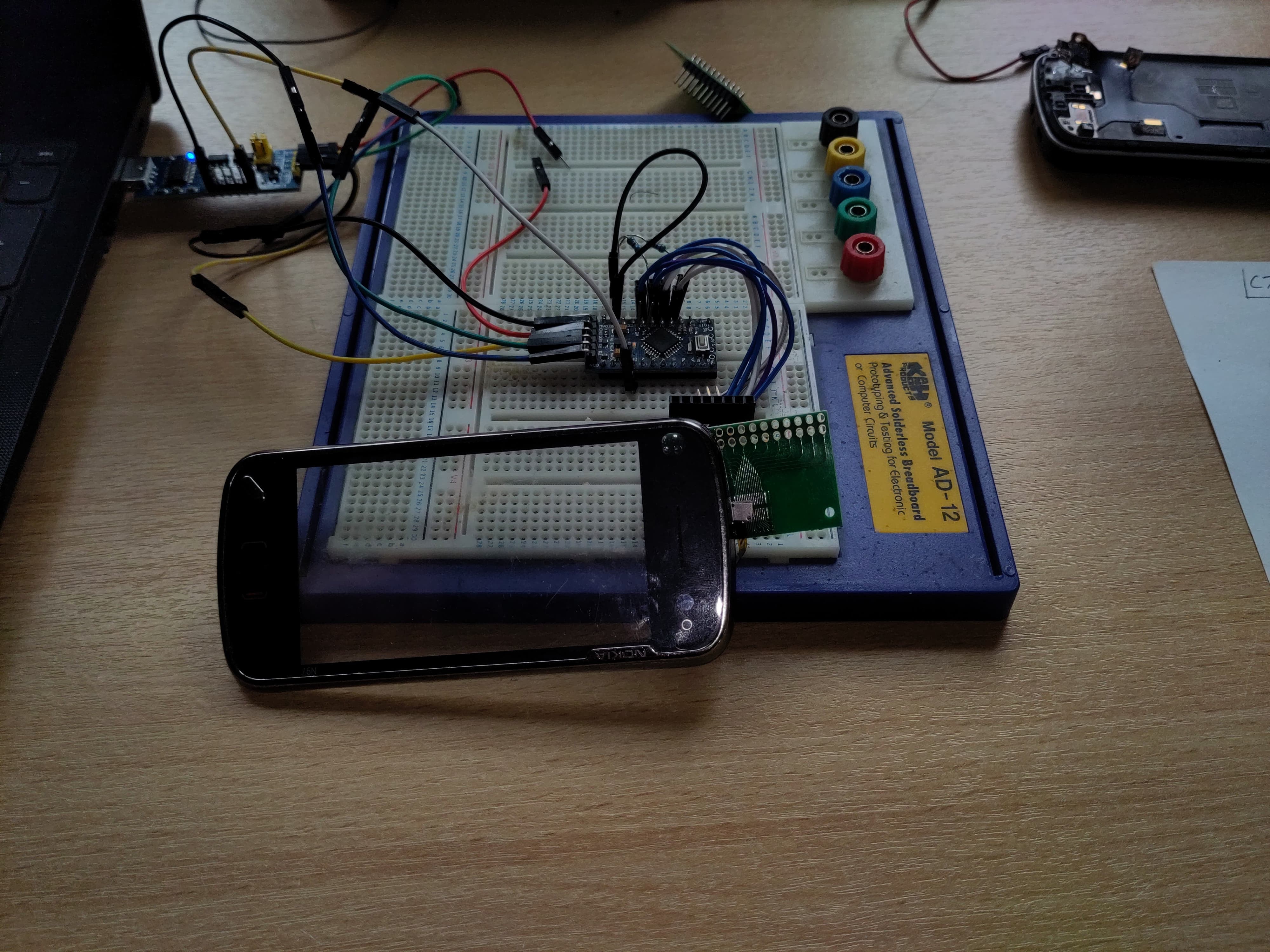
06/28/2025 at 08:05 • 0 commentsContinuing progress on the Nokia N97 cyberdeck build. This mornings focus was on getting the touchscreen tested and identifying the keyboard connector so I dont have to use salvaged connectors anymore.
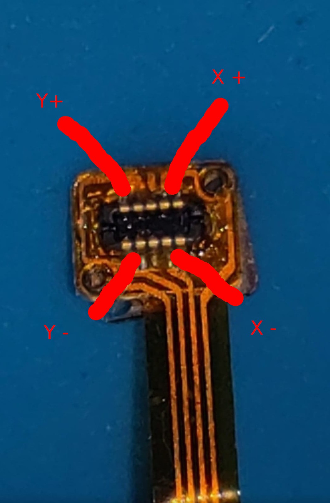
🔍 Touchscreen: 4-Wire Resistive Confirmed
The N97 touchscreen connects via a 4-pin flex cable. After checking Nokia's schematics and doing continuity tests, I confirmed it’s a 4-wire resistive touchscreen — no onboard controller.
Using a multimeter, I measured ~600 Ω across two separate pin pairs, consistent with
X+ / X−andY+ / Y−. That’s a standard configuration for passive resistive panels.I hooked it up to an Arduino using analog inputs:
-
X+,X−,Y+,Y−each went to analog-capable pins -
Added 10kΩ pull-downs to
X−andY−to ensure a clean 0V reference -
Powered the panel from 3.3 V to match logic levels
Using a simple test sketch, I was able to read stable X/Y positions through analogRead — and the values track consistently across the screen surface when touched. Success!
![]()
Touch screen flex middle pins are not connected
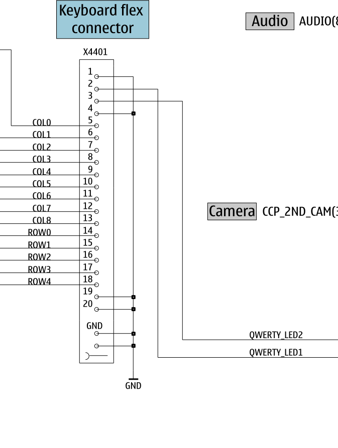
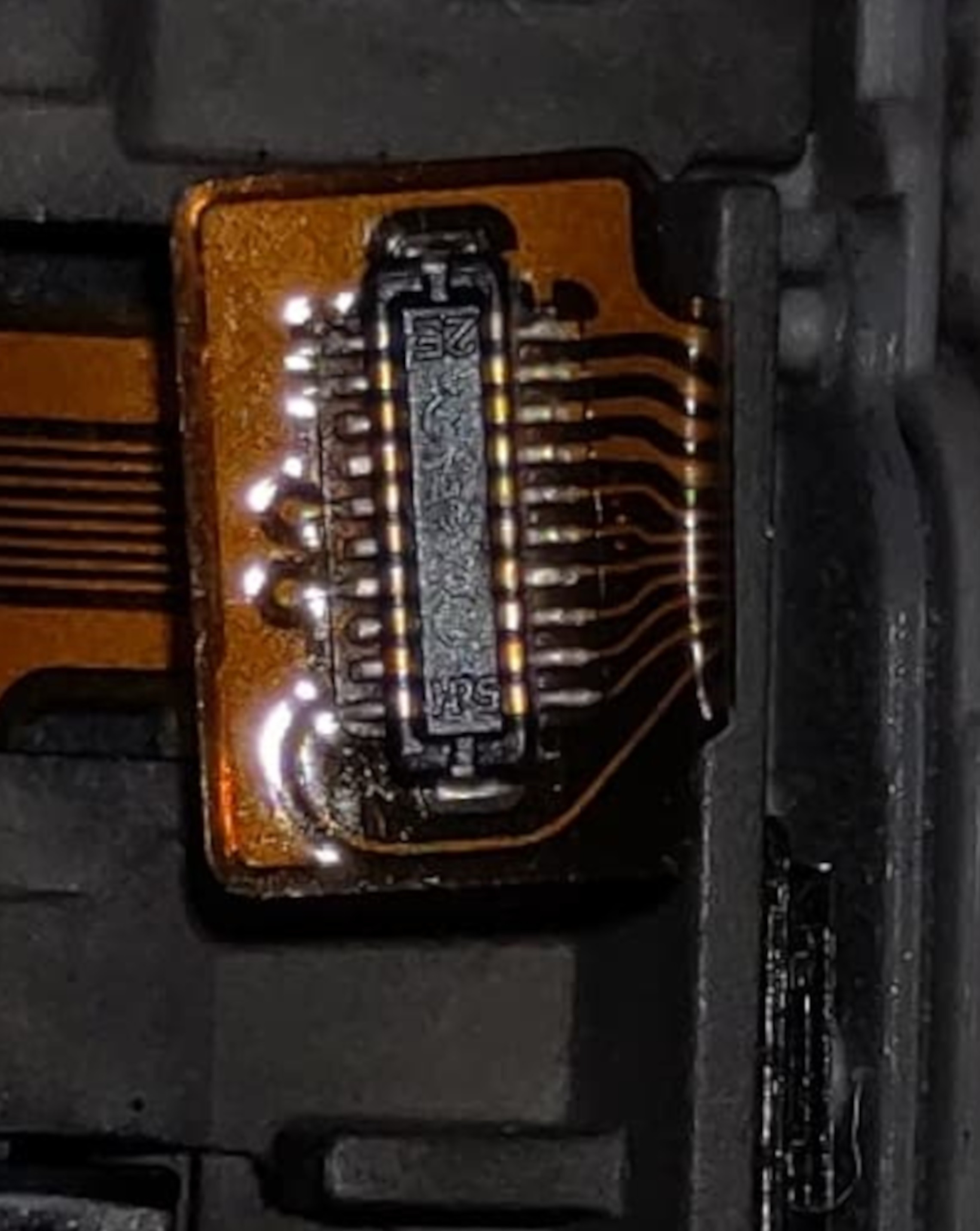
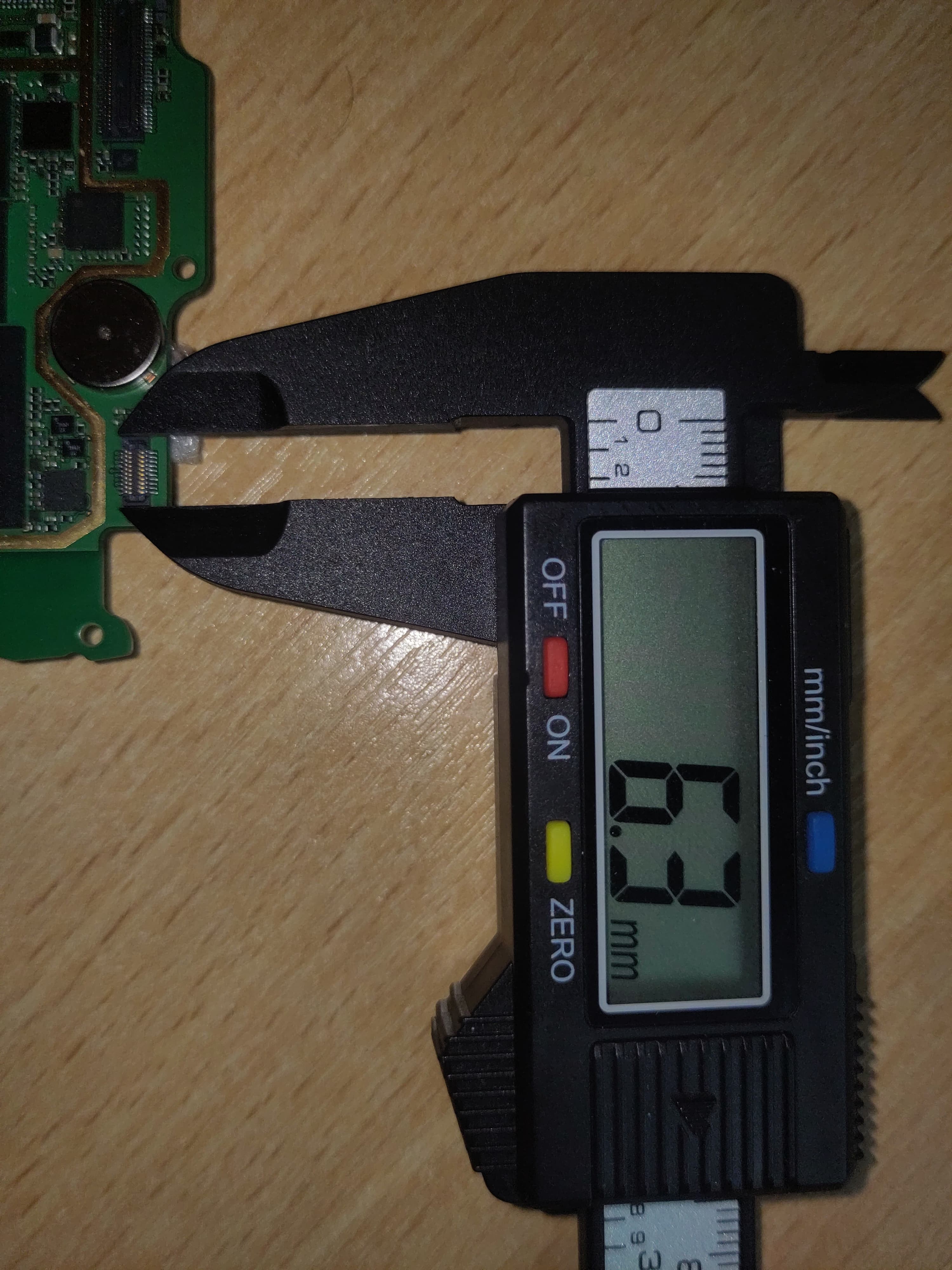
🧷 Connector Investigation: It’s a Hirose
While examining the keyboard and touch flex connectors, I noticed a small “HRS” logo printed on the keyboard flex. That stands for Hirose Electric, a major connector manufacturer.
After comparing mechanical dimensions and pin counts against their datasheets, I identified a match:
-
Hirose DF37NB-20DS-0.4V(51)
-
20 pins, 0.4 mm pitch, bottom-contact, ultra low profile
This matches the footprint and feel of the original X4401 connector exactly. Which means: I don’t have to rely on salvaged parts. These Hirose connectors are available new and can be cleanly integrated into custom PCBs.
![]()
![]()
-
-
Project Log #1 – Salvaging and Soldering by Eye
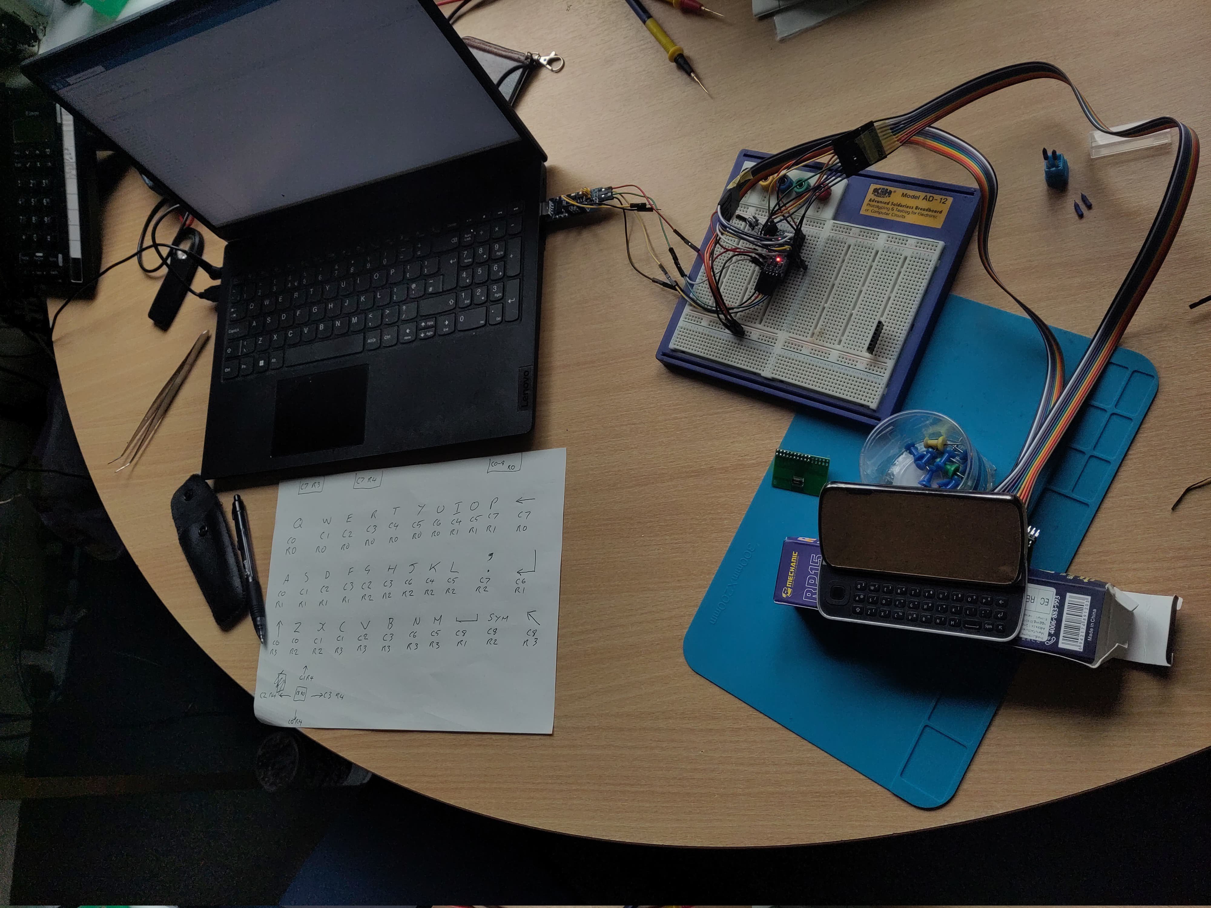
06/27/2025 at 21:24 • 0 commentsFirst challenge: interface the Nokia N97's original keyboard.
I desoldered the 0.4 mm pitch FPC connector (X4401) from the N97 mainboard. With no microscope or stencil, I used a combination of:
-
Tinning pads via drag soldering
-
Reflowing with hot air to seat the connector
-
Final drag pass with flux to clean and confirm joints
First try — no bridges, no lifted pads. All 20 pins mapped successfully.
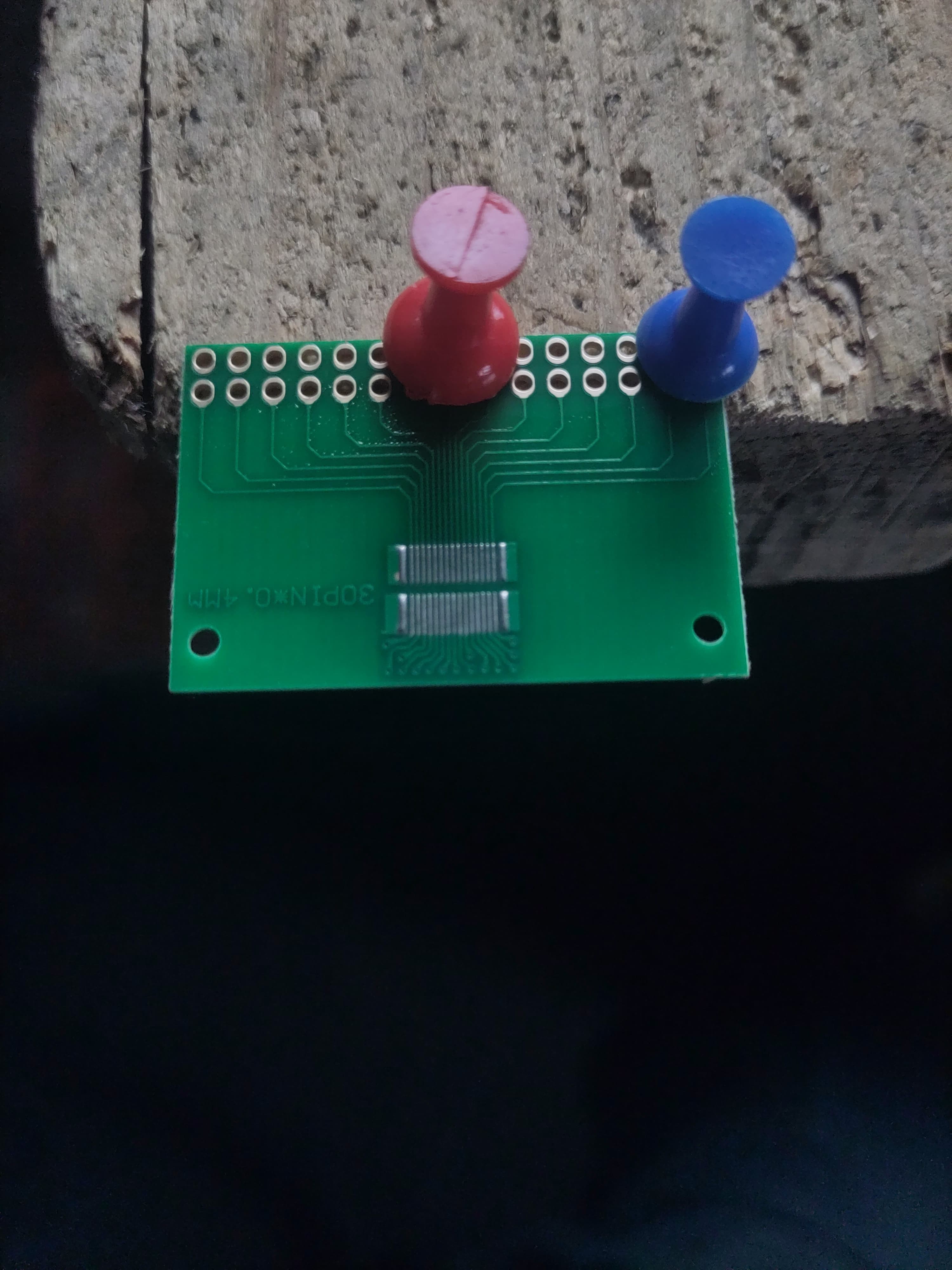
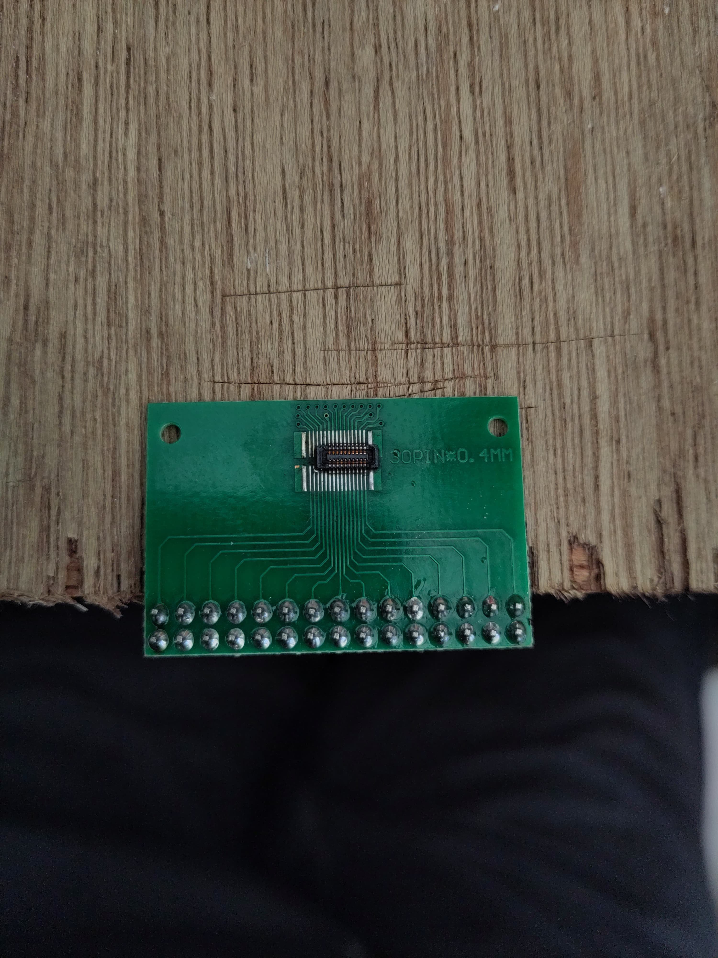
From Nokia’s schematic, I confirmed the keyboard runs on 3.3 V logic and has 3.3 V LEDs (verified via testing). I repurposed a double row 30 pin 0.4 pitch breakout board to route the FPC pins to a 2.54 mm header for prototyping.
I also identified the resistive touchscreen's 4-wire layout by resistance probing — no onboard controller, fully passive. Will drive it via an XPT2046 SPI controller.
The original LCD (LTJ035L001A) uses RGB input, but I’m currently adapting a Waveshare 3.2″ HDMI panel to fit the housing. The long-term plan is to build a custom HDMI driver board once I finalize display fit and power routing.
![]()
![]()
First attempt at 0.4 pitch pad tinning
![]() Salvaged and resoldered 20 pin FPC. No bridges on any of the FPC pins
Salvaged and resoldered 20 pin FPC. No bridges on any of the FPC pins![]()
Keyboard mapping.
![]()
I’ve added an Excel spreadsheet to the Files section with the full keyboard matrix mapping — based on testing and confirmed against the Nokia schematic. This includes pin assignments, row/column layout, and working key labels -
Nokia N97 Cyberdeck Resurrection
Rebuilding a Nokia N97 into a pocket Linux cyberdeck with SBC, HDMI display, original keyboard, and touchscreen.
 Salvaged and resoldered 20 pin FPC. No bridges on any of the FPC pins