Close
0%
0%

8-bit RISC CPU from TTL logic

yet another RISC CPU from TTL chips.

Similar projects worth following
8 bit RISC CPU, revisited.

A simple RISC CPU made from TTL chips. Why? Just for the fun, to return to basics of digital circuit design.

In prior completed project, I built simple 4-Bit RISC CPU.

This project is expansion of the same architecture to 8-Bit RISC CPU.

Data is 8 bit, and address is 10 bits, (1 KB address space).
Add and Subtract instructions, and I/O ports, and 1 KB RAM.

Simple 8-Bit RISC CPU and computer.

Uses only 20 logic chips, 2 EEPROM, and 1 SRAM chip, and one 555 timer.

This just shows simple RISC CPU made from small number of parts.

Design choices:

Uses Harvard architecture, with separate instruction and data memory.

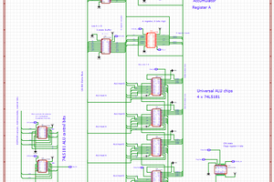
CPU made from discrete logic chips. Fits on single PCB.

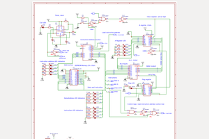
Clock is generated by 555 timer with frequency from 1 Hz to 1000 Hz. Although  schematic will probably allow frequency up to 1 Mhz.

Instruction format 16 Bit, with 6-bit opcode, and 10 bit address or 8 bit data.

Instructions stored in two EEPROM chips. Address space is 10 bits ( 1  KB).

Data stored in SRAM ( 1 KB), address is 10 bit.

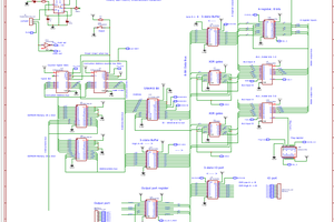
Each instruction executes in 1 clock. This simplifies control logic.

On positive edge of the clock, instruction executed. 

On negative edge of the clock, instruction address is incremented.

One 8-bit accumulator register A.

ALU instructions: Add and Subtract and clear Accumulator.

One output 8-Bit port, and one input or bidirectional 8-Bit port.

Instructions set is very small but allows to execute short programs. 

Instruction format is 16 bit. 

Instruction consists of 6 bits opcode, and 10 bits address, or 8 bits immediate operand.

Instructions:

No-op.

Clear Accumulator A. ( zero to A)

Add operand to A and store in A.

Subtract operand from A and store to A.

Store value from A to SRAM at address N.

Input operand from input port and add to A.

Output value A to output port. 

Jump conditional when Flag overflow.

Jump unconditional.

Operand for Add or Subtract instructions can be:    immediate value # from instruction EEPROM,

      value from SRAM at address N,

      value from input port.

      value from accumulator A (add to itself).

Notes:

There is no load A instruction. But one can use ‘Clear’ instruction, following by ‘Add’ instruction to load value to the A accumulator.

ALU and Accumulator operate on 8 bits. But program can compute multi-byte arithmetic operation (add or subtract 16 or 32 bit numbers), in multiple steps.

There is only one conditional Jump instruction and flag carry. But one can use it to test different conditions. For example, to test if A register in not zero: Add value hex FF to A. If flag carry is set then the value in A was not zero.

Input and output 8 bit ports can by connected to devices, like 7-segmend LED display, and keypad, for example.

PCB_PCB_P12345-2025-Jul4-8bit-10b_2_2025-07-05.pdf

PCB design, PDF, Easyeda

Adobe Portable Document Format - 356.43 kB - 07/06/2025 at 03:24

Preview

Schematic_P12345-2025-Jul4-8bit-10b_2025-07-05.pdf

Schematic, PDF , Easyeda

Adobe Portable Document Format - 324.32 kB - 07/06/2025 at 03:24

Preview

View project log

  • 1
    CPU instruction set

    Instruction is 16 bits wide.                    
    6 bits opcode.
    Address is up to 10 bit (1kb),
    Immediate Data is 8 bit. 
    There are 14 instructions:
    _______________________________________
    adddres/data    CPU opcode            
    10 bits         6 bits Hex
               0      00  h - Noop            
               0       01  h - clear Accumulator A (A=0)            
    ...address    02  h - jump conditional if overflow            
    ...address    03  h - jump unconditional            
    ...#data..       0C  h - add immediate data to A            
                0      0D  h - add value of A to A (A=A*2)            
    ....address    0E  h - add value from SRAM to A            
    .... port..        0F  h - add value from input port to A            
    ....#data..      14  h - subtract immediate data from A            
                  0    15  h -  subtract value of A from A            
    ....address    16  h - subtract value from SRAM to A            
    .....port..        17  h - subtract value from input port from
    ....address    1D  h - store value A to SRAM by address    
    .....port..        25  h  - write value A to output port    

    Notes:
    There is no Load instruction. But one can use Clear accumulator, followed by add instruction to load value.
    There is only one flag Carry (overflow). But it can be used to check different conditions, i.e. not zero, lesser than, and so on.
    ALU is 8 bits wide. But multi-byte numbers can be added or subtracted in several steps, using carry flag.

View all instructions

Enjoy this project?

Share

Discussions

Similar Projects

Does this project spark your interest?

Become a member to follow this project and never miss any updates