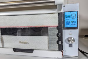
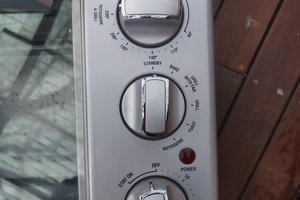
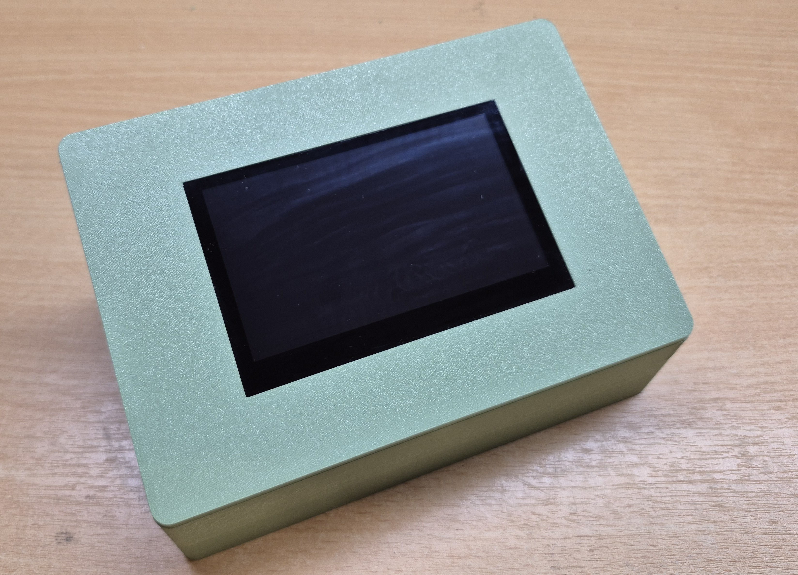
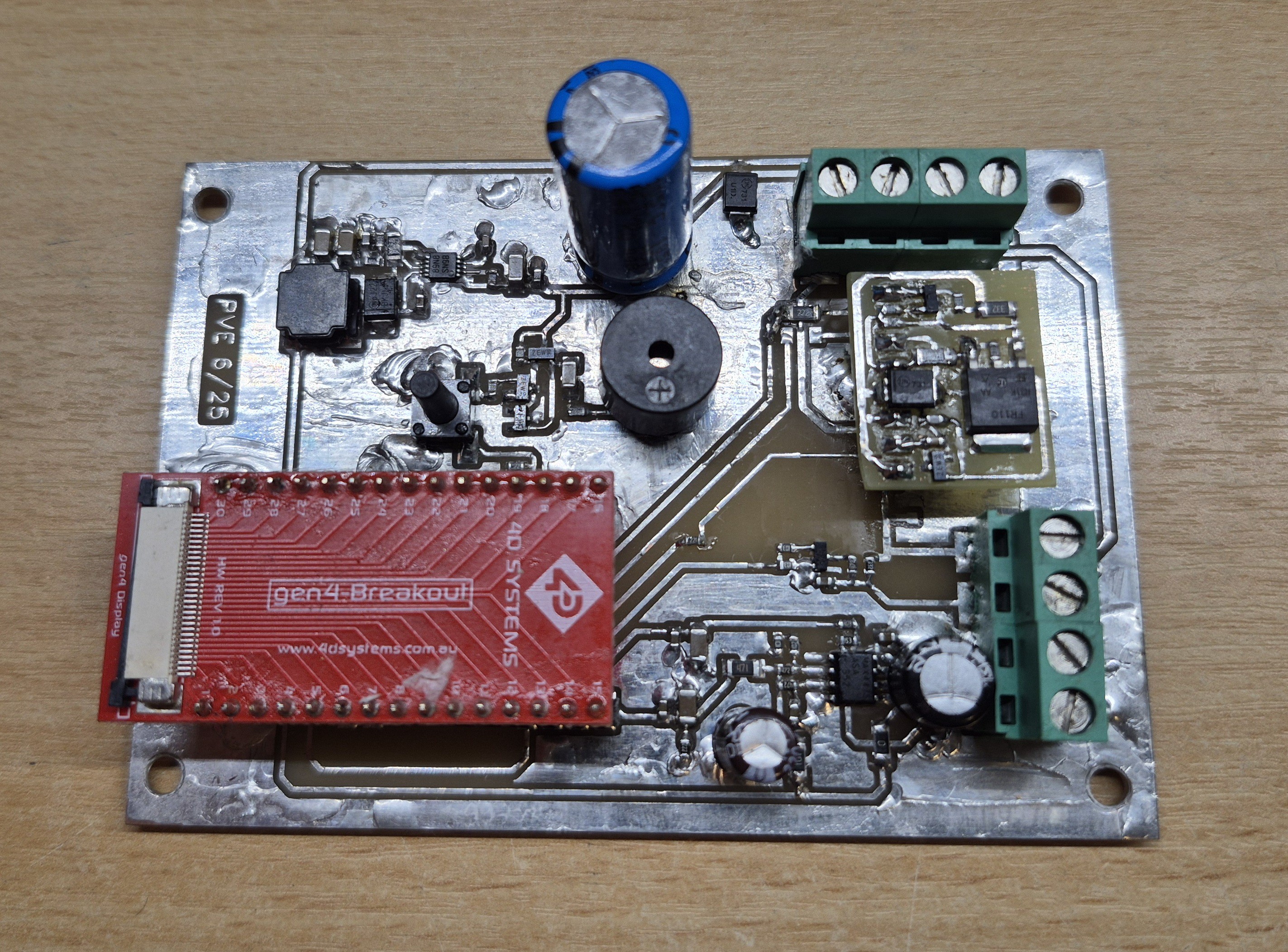
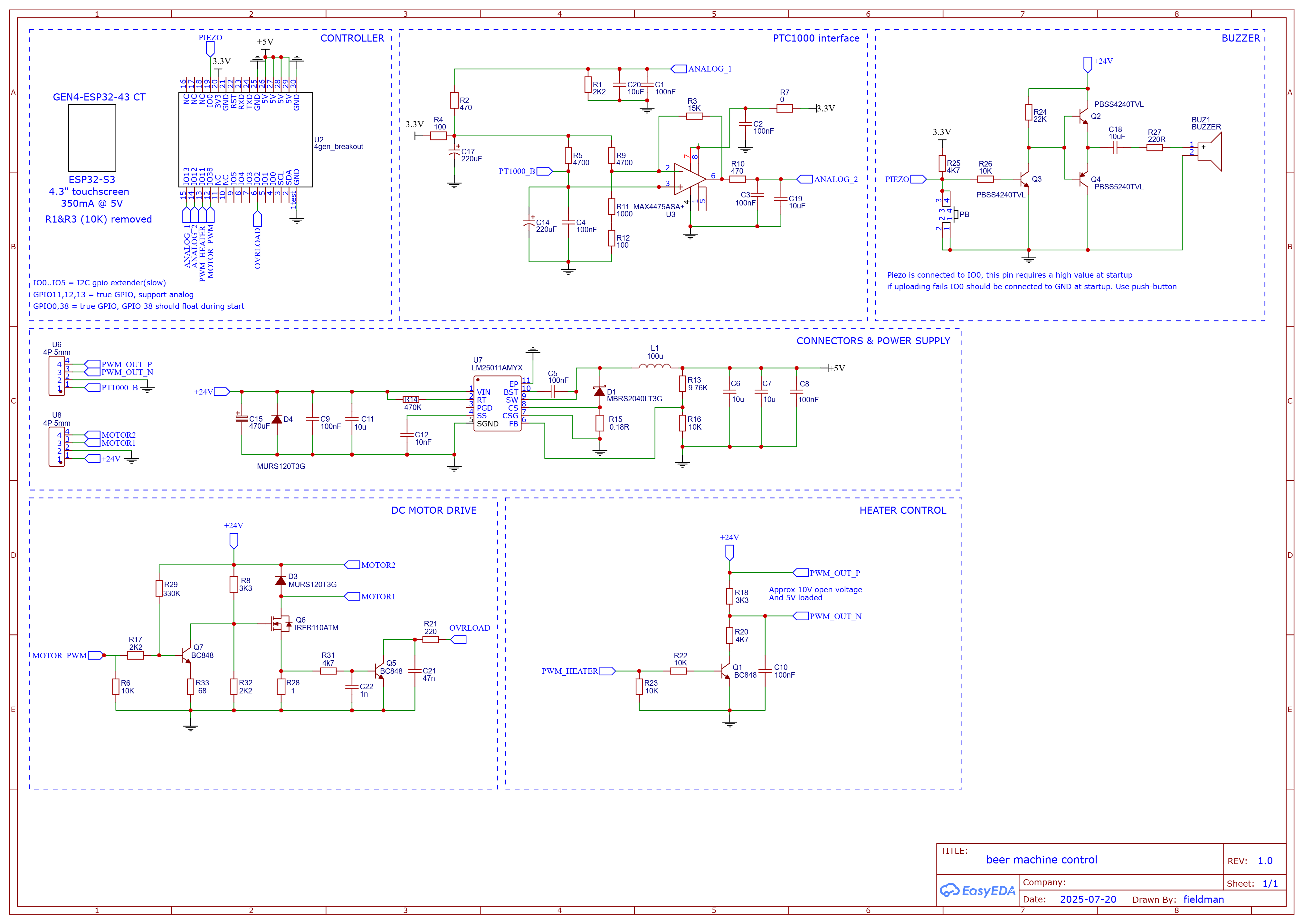
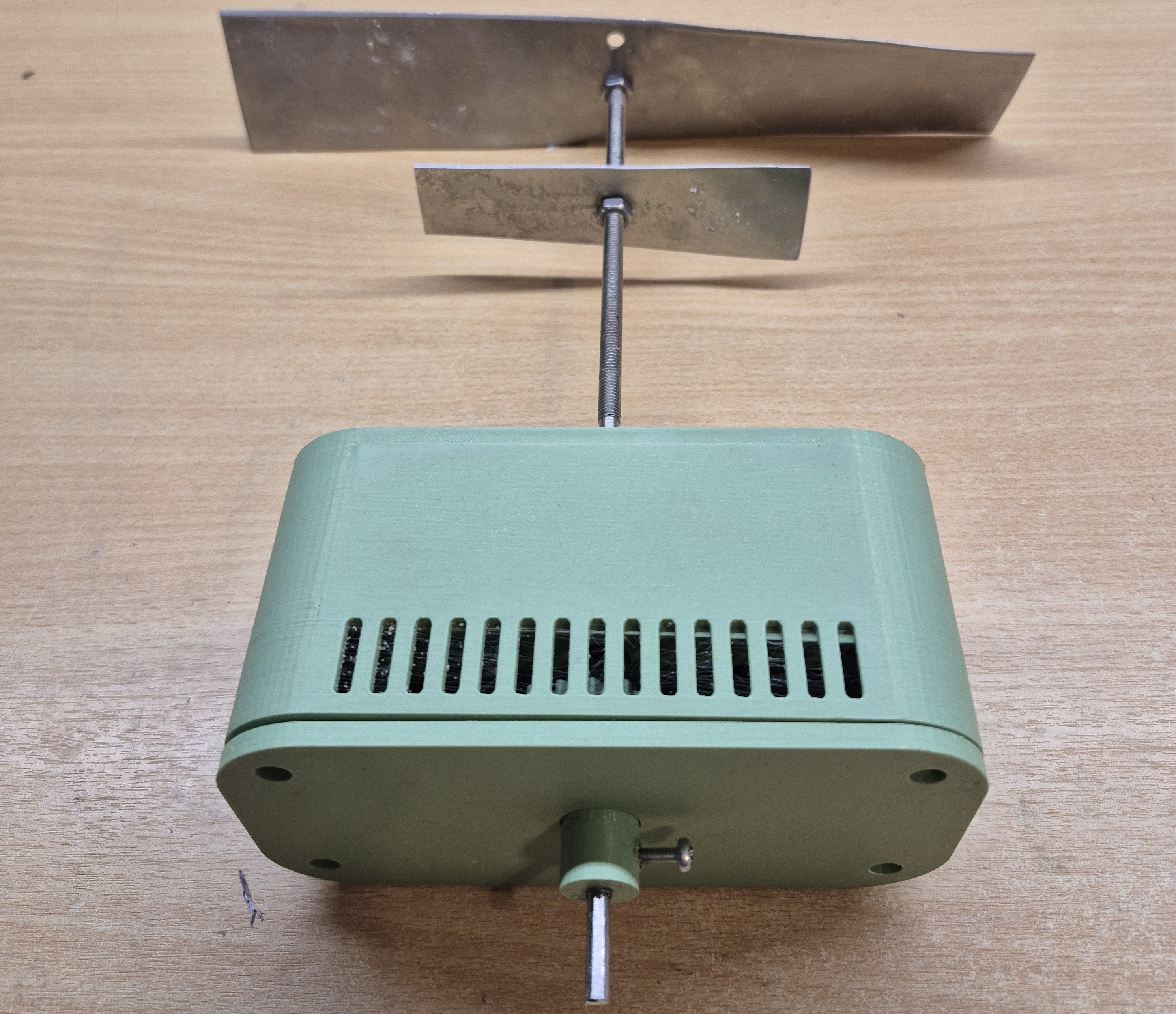
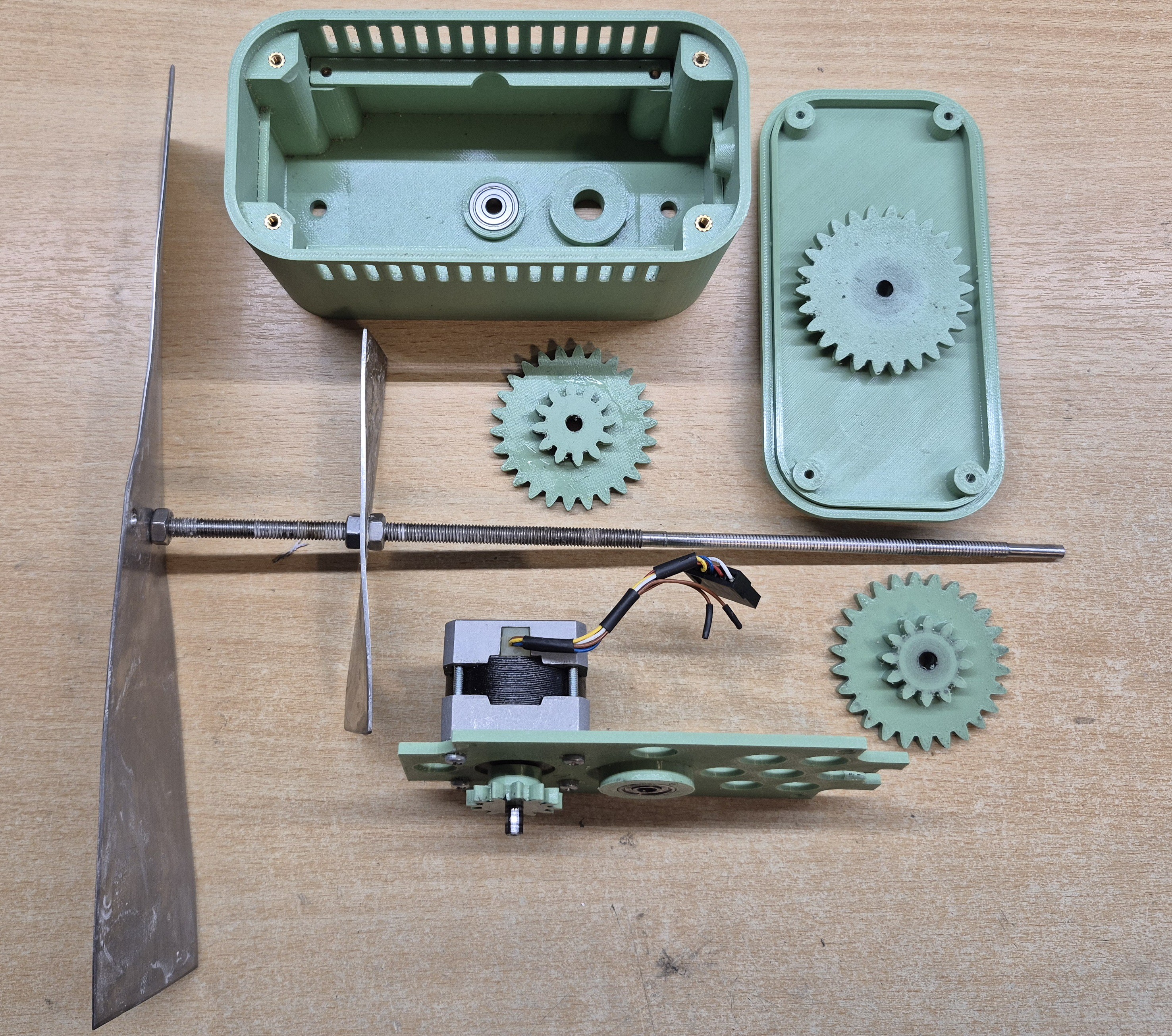
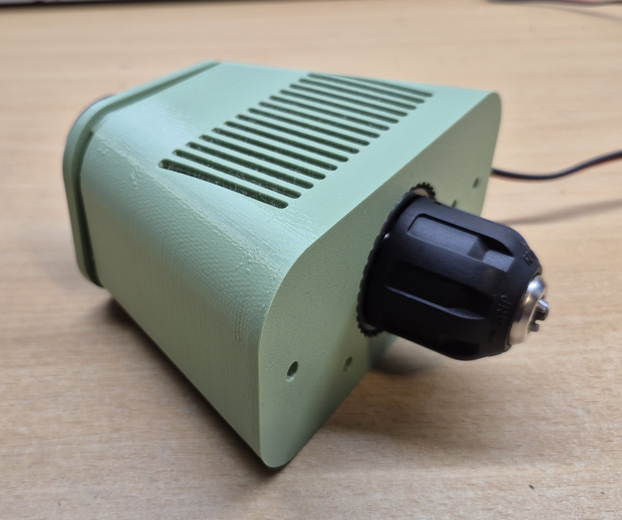
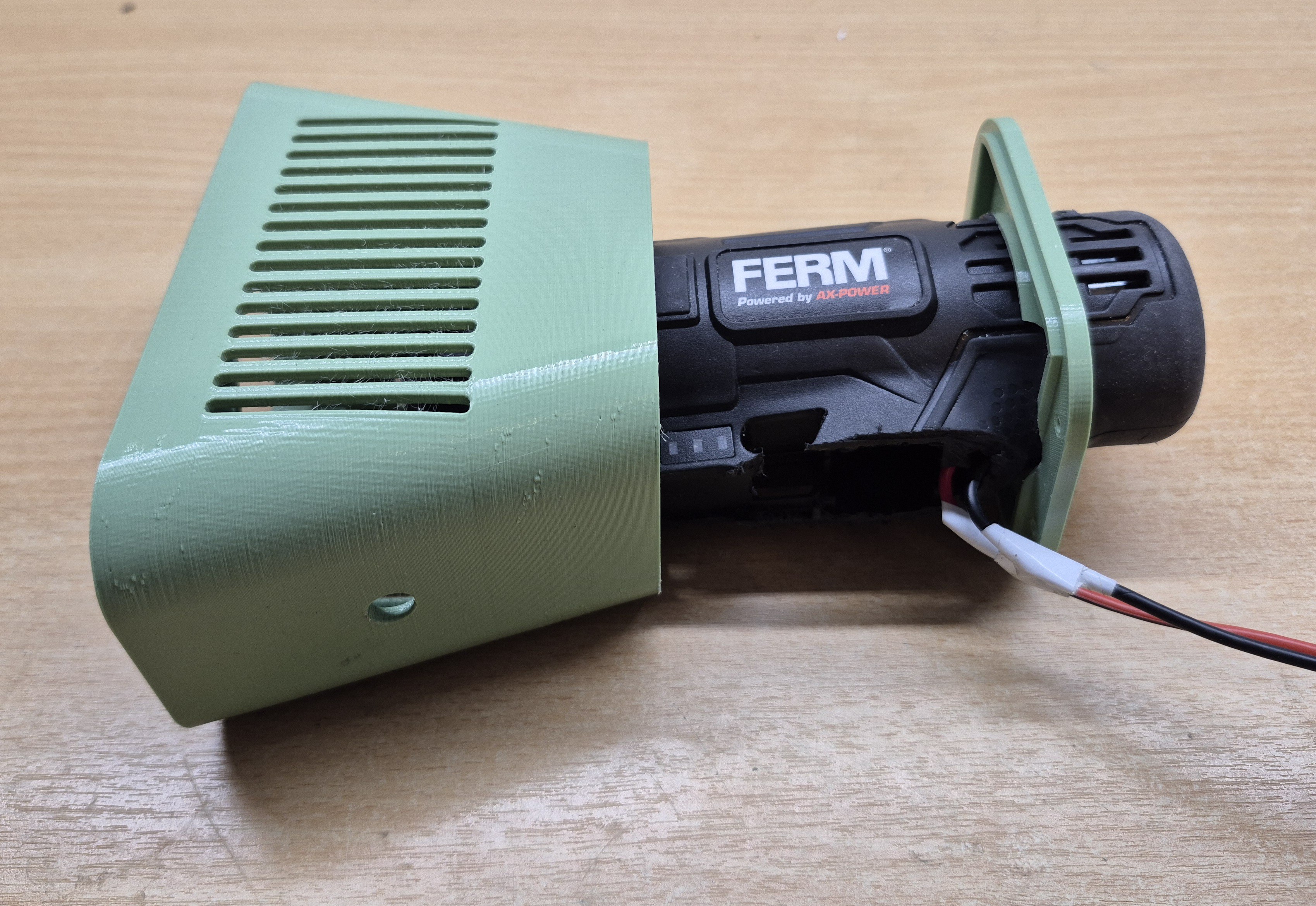
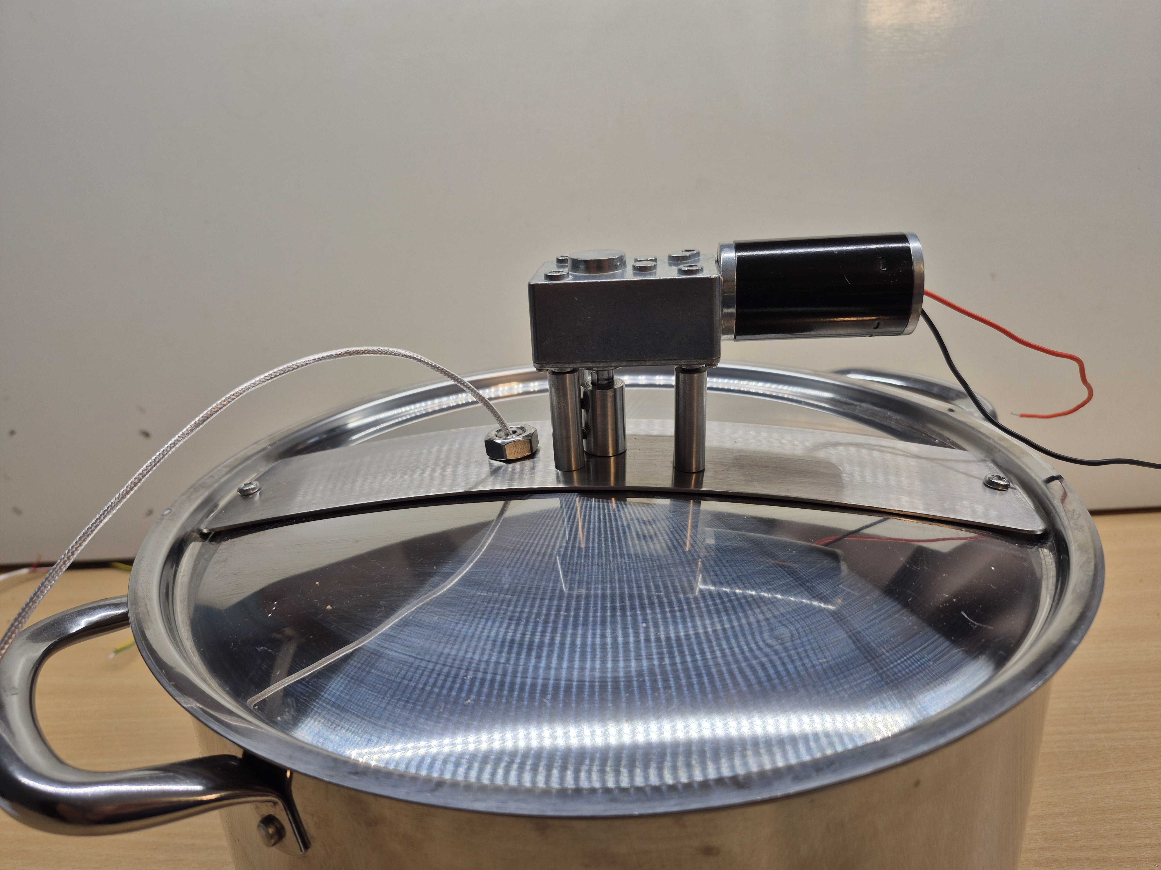
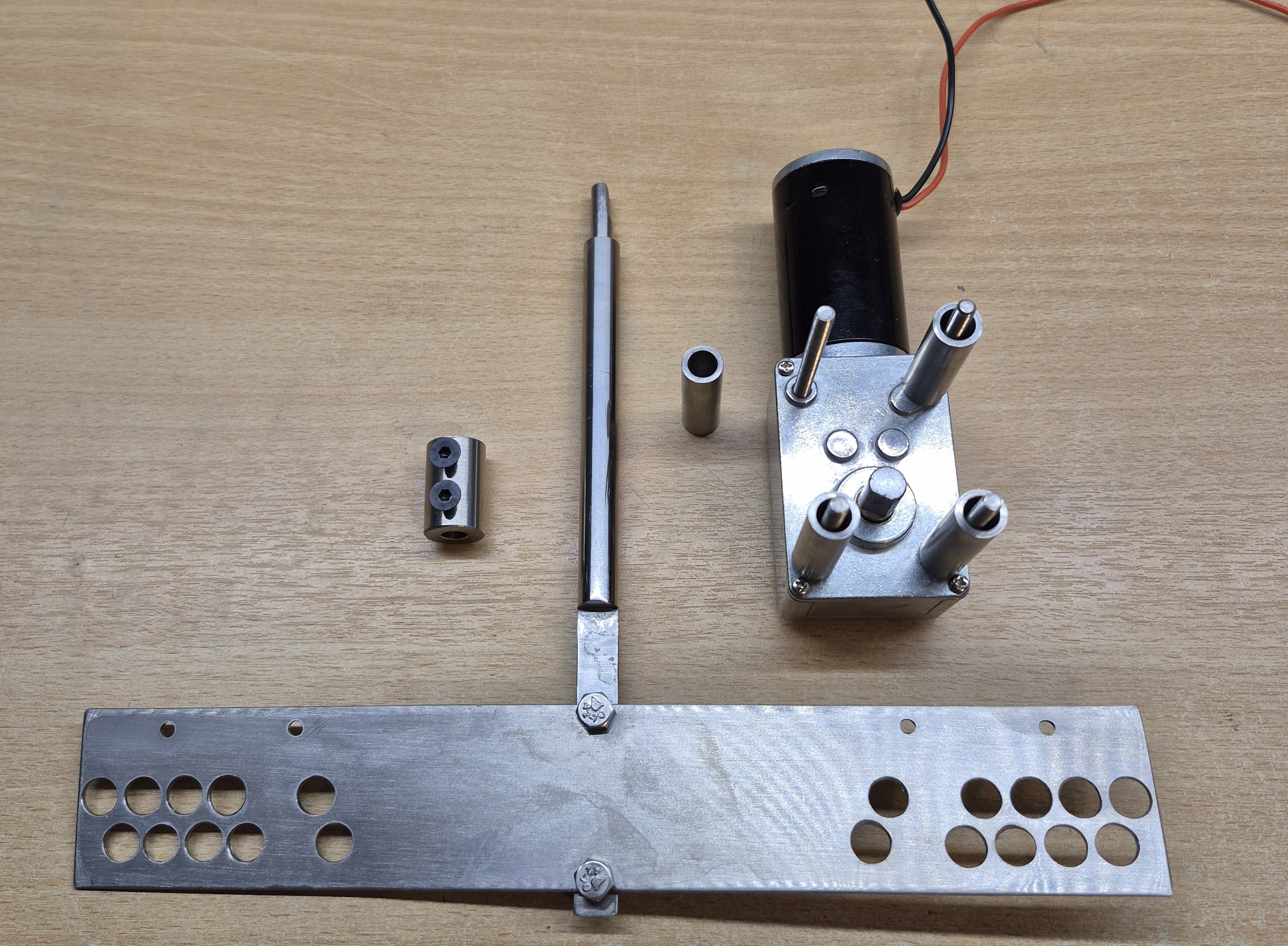
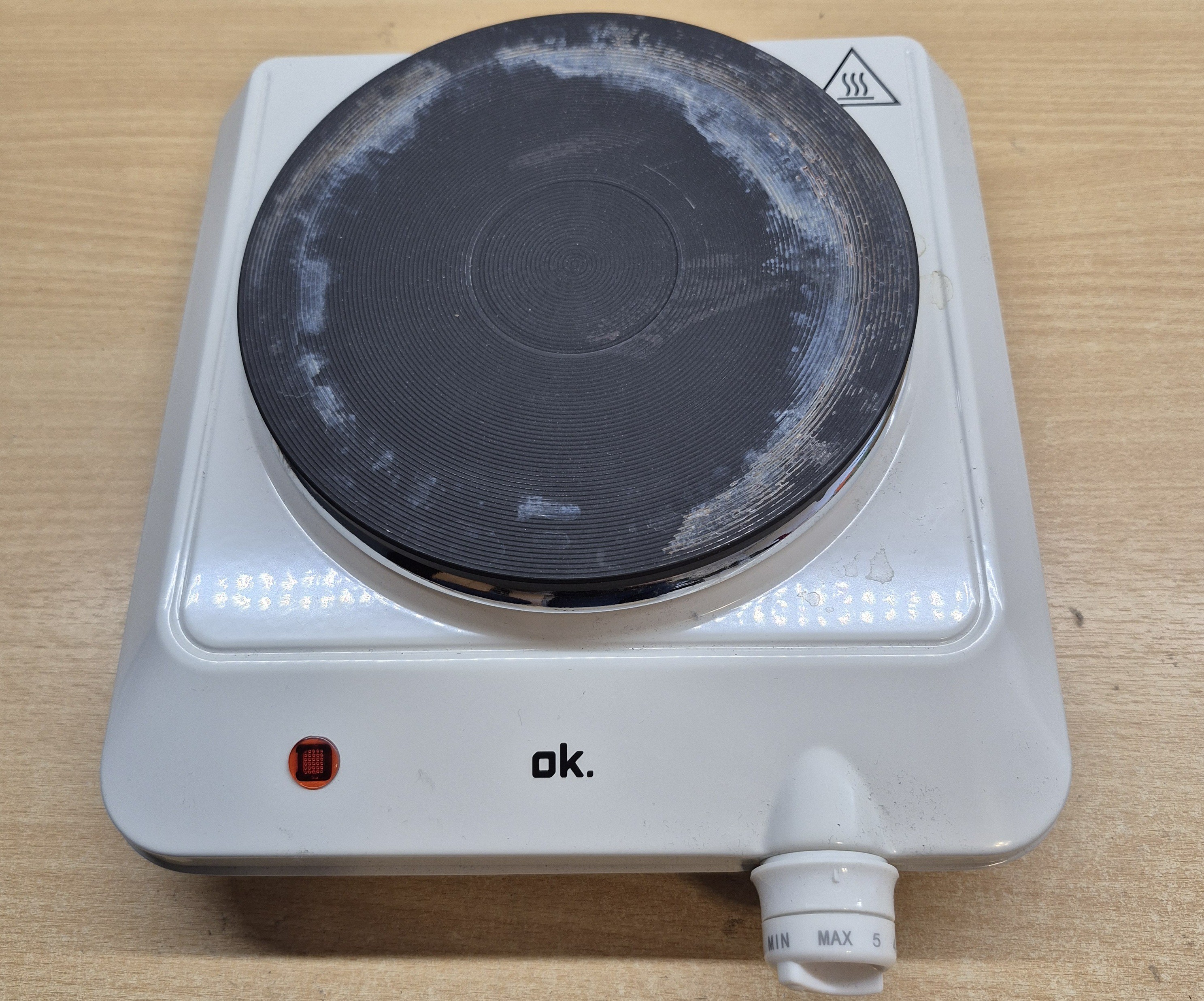
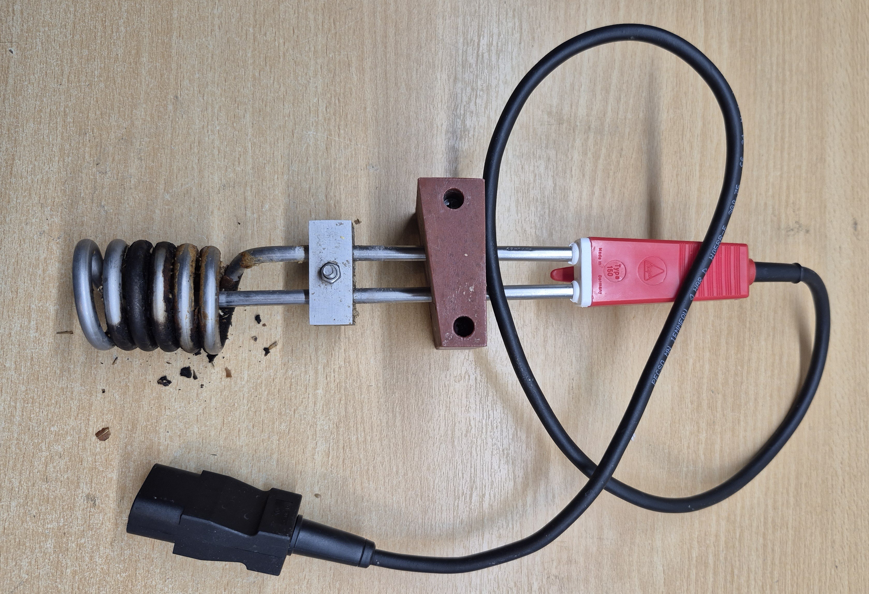
I’ve been brewing small batches of beer in my kitchen using a 10-liter cooking pot on the stove. Starting from malted grain, the process takes about three hours of manual stirring and careful temperature control.
To reduce the labor involved, I decided to automate the process. The 10-liter volume is ideal for me—small enough to experiment with different beer styles rather than producing large quantities. Most of my brews are strong, with alcohol content around 10% ABV, like Belgian triples.
After extensive experimentation, I am ready to bring everything together:
• A mechanical setup mounted on the pot lid for stirring and temperature measurement
• A controllable heating element for precise temperature regulation
• An ESP32-based controller with a touchscreen display to program and run the mashing and cooking process autonomously,
• A dedicated housing for the electronics and interface
Files
pngToArray_beermachine .zip
c# tool to convert png files to c++/header format usable by the arduino code
For this project, I repurposed a 4D Systems 4.3” touchscreen display with an integrated ESP32-S3 processor. I originally bought it for a previous ground-penetrating radar project, but ended up using an Android app instead of a display for that build.
In this case, I felt having a local display was much more practical—it clearly shows what’s going on during the brewing process and makes the system easier to use without relying on a phone or external device.
The ESP32-S3 is a powerful little chip with built-in Wi-Fi and BLE, so adding remote control via an Android app is still a possibility for the future. But for now, the touchscreen gives me all the interaction I need.
GEN4-ESP32-43 CT mounted on a 3d printed enclosure
All parts of the enclosure with the PCB mounted inside
And this is the how it looks assembled.
In addition to the 4D Systems controller, there's a support PCB that includes the following circuits:
24V to 5V switching regulator
Buzzer driver
PWM motor driver
PWM output for controlling the IKEA induction heater
Analog interface for the PT1000 temperature sensor
I prefer to etch my PCBs at home, so to keep things simple, all components and signal traces are placed on one side, with the other side used solely as a ground plane.
This is the complete schematic :
The system is powered by an external 24V, 750mA power adapter.
I started with a stepper motor paired with a 1:10 reduction gear to drive the stirring mechanism. However, I underestimated the resistance of the mash—it turned out to be too thick and heavy. The stepper motor just didn’t have enough torque to spin the stirrer at a decent speed. It managed around 20 RPM, which worked, but I wasn’t happy with the resulting temperature differences in the pot (up to 5°C) due to insufficient mixing.
Next, I tried using a cheap battery-powered screwdriver, mounted on top of the lid with stainless steel supports. This motor had plenty of power, and the integrated chuck was convenient—it eliminated the need for extra bearings. Unfortunately, the minimum speed was too high for proper stirring, so I had to abandon that solution too.
Eventually, I looked for a DC motor with an integrated gearbox, and found one on Amazon. I’m very happy with it—it’s quiet, powerful, and fits the job perfectly. I chose the 24V 100 RPM model, but if I were to do it again, I’d probably go for the 50 RPM version for its higher starting torque, which would be more than fast enough for this use case.
Using my lathe and benchtop milling machine, I machined:
A coupler to connect the motor to the stirrer shaft
A stainless steel shaft with a flat edge for securing the blade
4 studs to mount the motor
For the stirring blade, I experimented a bit. I added large holes to reduce drag and improve mixing. The blades are tilted at 10° to promote vertical flow. I also drilled small holes near the top so I can later attach extra surface area if needed, to improve flow across the entire volume.
I decided to mount both the stirring motor and the temperature sensor on the lid of the pot. This way, I could avoid drilling any holes in the cooking pot itself.
For accurate readings, I chose a PT1000 sensor—robust, not too expensive, and easy to interface with the ESP32’s ADC. I used a 3-wire PT1000 housed in 4mm 316L stainless steel, with a 1-meter cable.
To mount it securely and make it watertight, I machined a custom holder using my Proxxon PD400 lathe—one of my favorite tools. It belonged to my late father, so using it always reminds me of him.
I started with a M10 stainless steel threaded rod, removing most of the threads except for a small section to allow mounting with two M10 nuts. I then drilled a 4mm hole through the center of the rod and inserted the sensor, sealing it with a bit of PTFE tape to ensure a watertight fit.
I started with a 1500W resistive cooking plate, but regulating temperature with it was a nightmare due to its inherent delay. I tried everything to optimize the PID control, including lambda tuning, but only very slow regulation produced stable results.
I found two key reasons for this behavior:
The thermal inertia of the cooking plate causes the temperature to overshoot by more than 5°C after cutting the power.
During mashing, recovery from an overshoot is very slow, since it only takes a tiny amount of power (about 3% of 1500W) to maintain a steady 55°C.
So I abandoned that approach.
Next, I switched to a cheap 1500W immersion heater—a simple spiral-type element. Temperature regulation was excellent: I could keep the heater at 100% power right up to 1°C below the target without overshooting. But eventually, grain clogged the spiral, which led to burned grain.
After that, I considered using a ceramic cooking plate, assuming it would be more responsive. Unfortunately, I couldn't find an affordable model that met my needs.