Progress:
Hardware design:
- Defining the motor
- Architecture & hardware shutdown
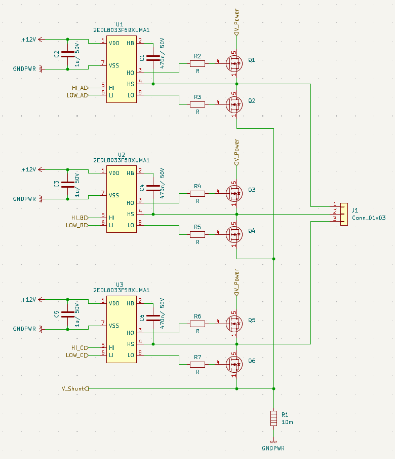
- Output stage
- Overcurrent and shutdown
- Sensor connection
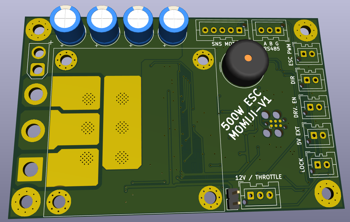
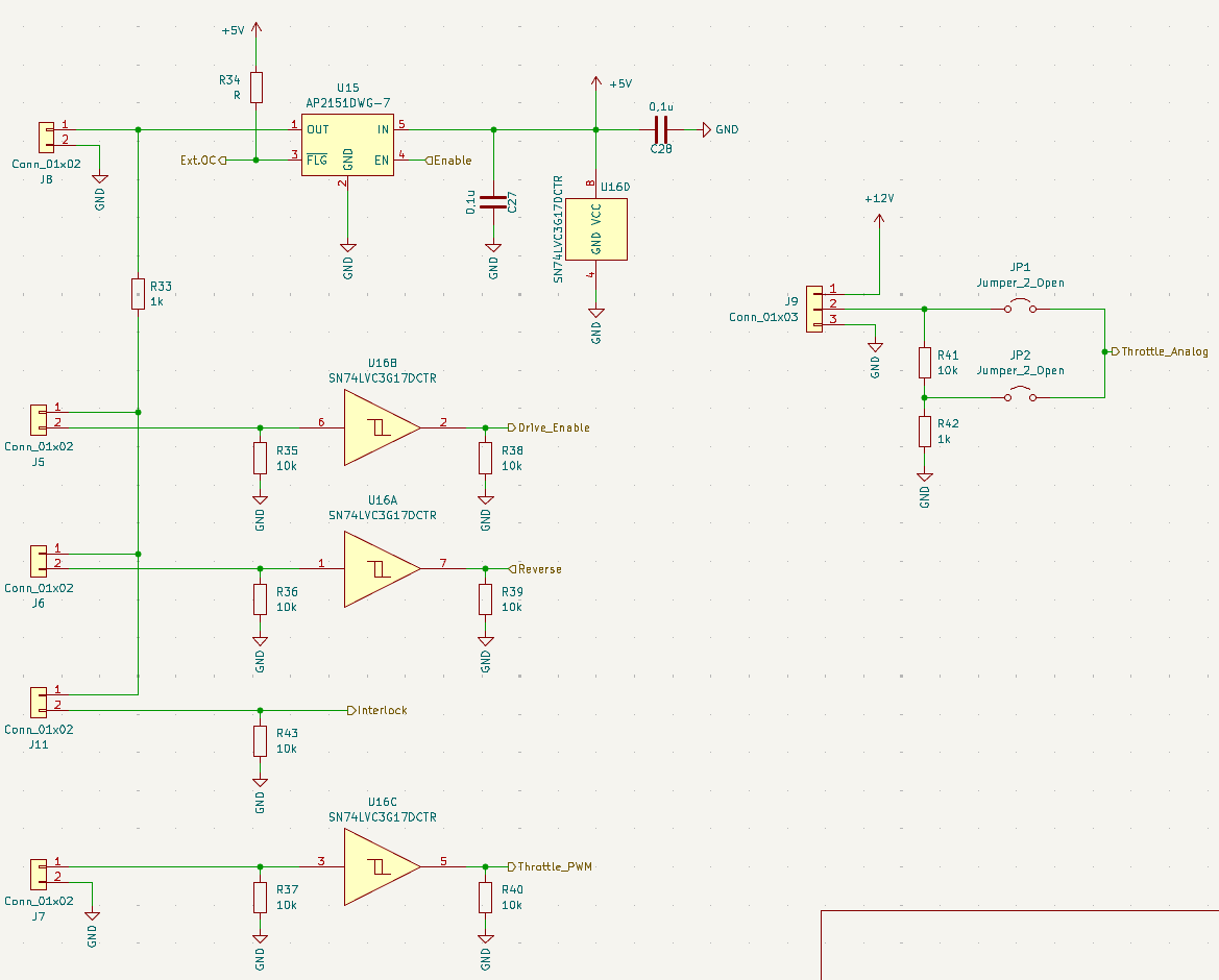
- User input
-
-
The plan:
The driver shall have following functions:
Motor:
- 36V/15A
- External 5V for sensors
- Analog overcurrent shutdown
- At least block commutation (no FOC for now)
- Speed feedback
Peripherals:
- Temperature sensing
- Either 12V throttle or PWM input
- Emergency shutdown capability
- Serial connectivity
- USB configuration

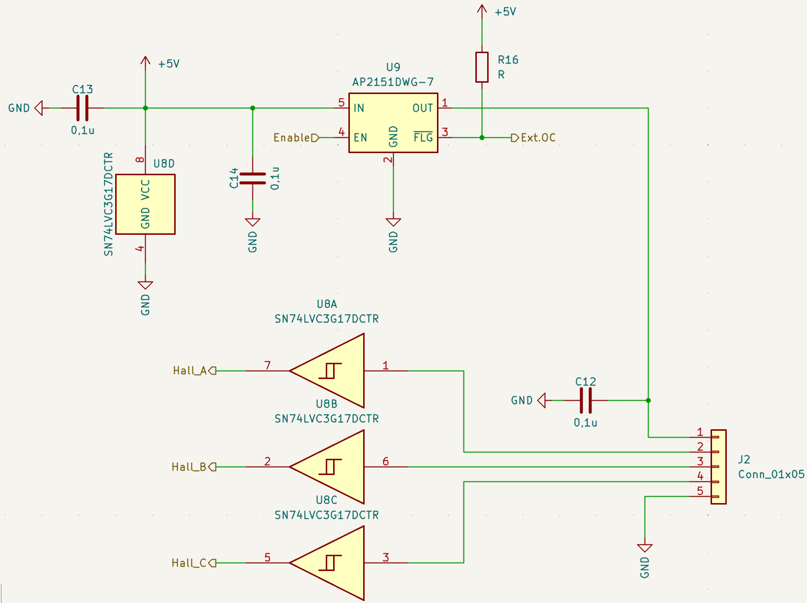 Another important part. The connection to the sensors.
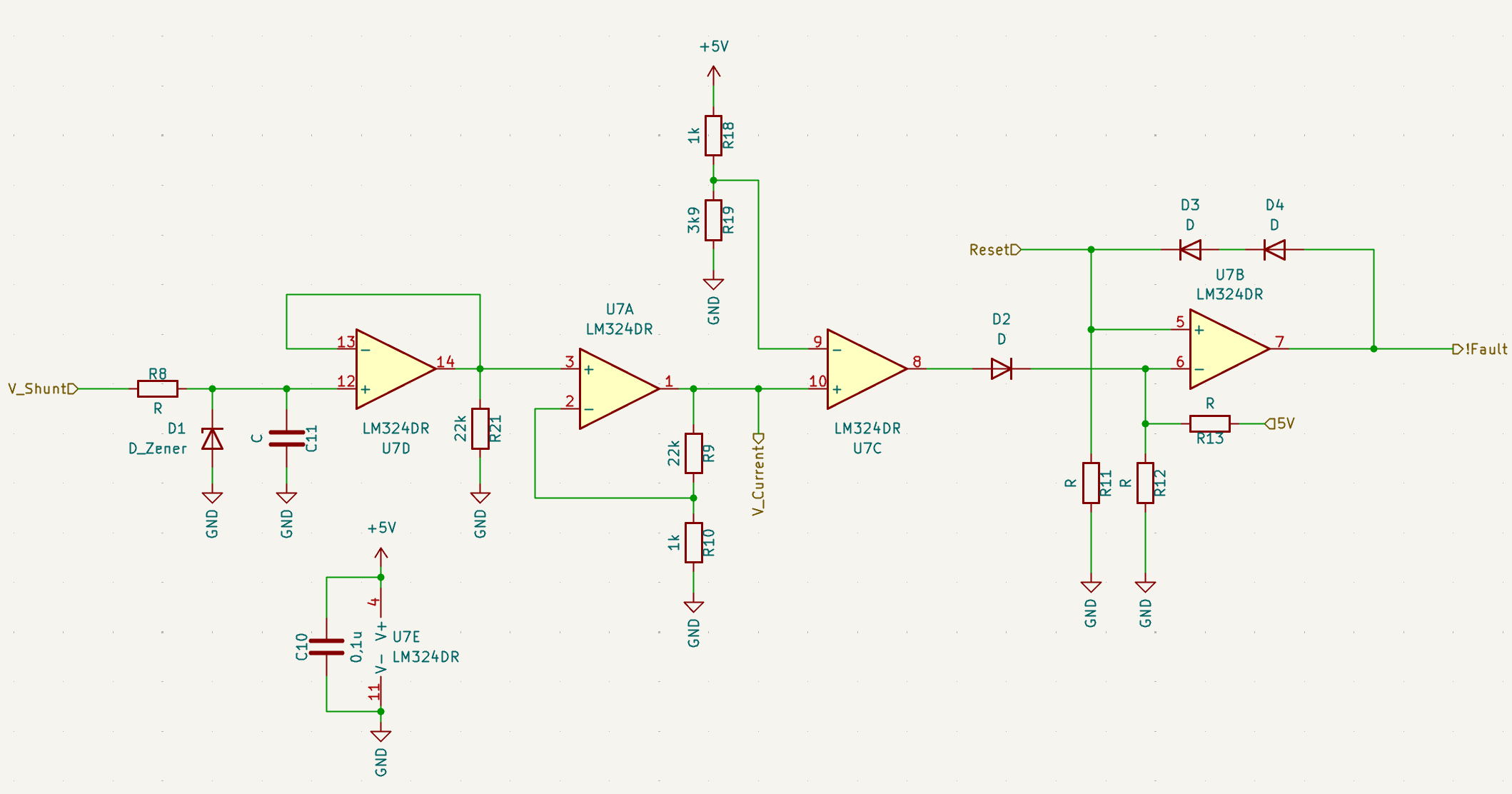


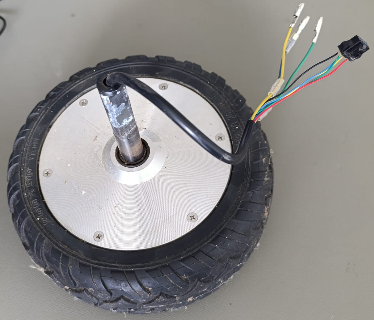 These (propably chinese) hubmotors dont have any useful marking that would let us find a datasheet or anything so we need to make some assumptions.
 Les Hall
 matseng
 ClimbinElectronics
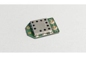
 Christoph