I stil was quite unsatisfied due to the little wasted space left. Also i noticed going to a 4-layer pcb while getting smaller is also not much more expensive.
So i redesigned it with the premise to use a 4-layer pcb and went down to a nice credit-card format 85x55mm BABY!
And the fun part ...... somehow i still managed to stay on a 2-layer pcb XD
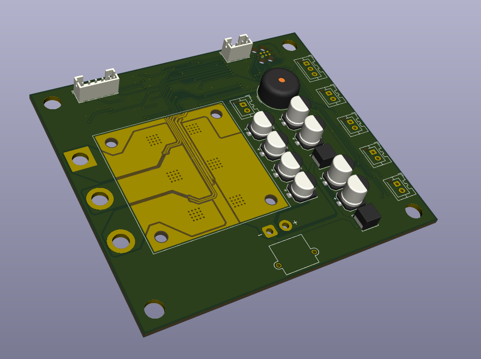
I changed up some things and managed to get it smaller
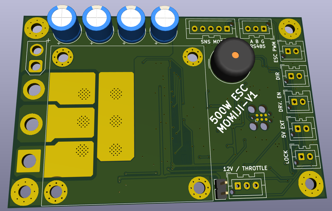
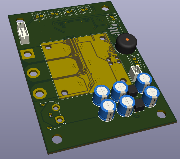
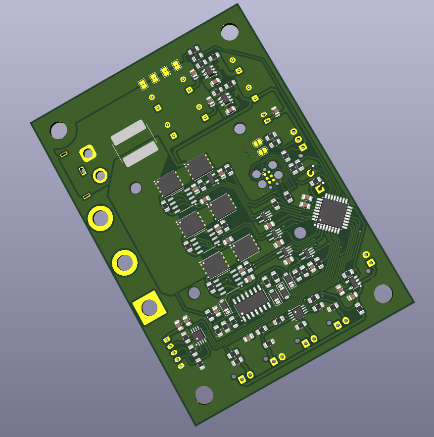
Everything is now in a neat 95 x 67mm form. Plan still is to have the heatsink + optional fan on the top side, along with "large" components + conectors. Since i will have an enclosure as well, all SMD components will be on the bottom side :
Plan is to mount the heatsink and large components on the bottom layer and all smd components on top. I also found a nice 50x50mm one that fits and even a fan.
-
However im quite unsatisfied with the layout of it. So i will redo it and see where it takes me.
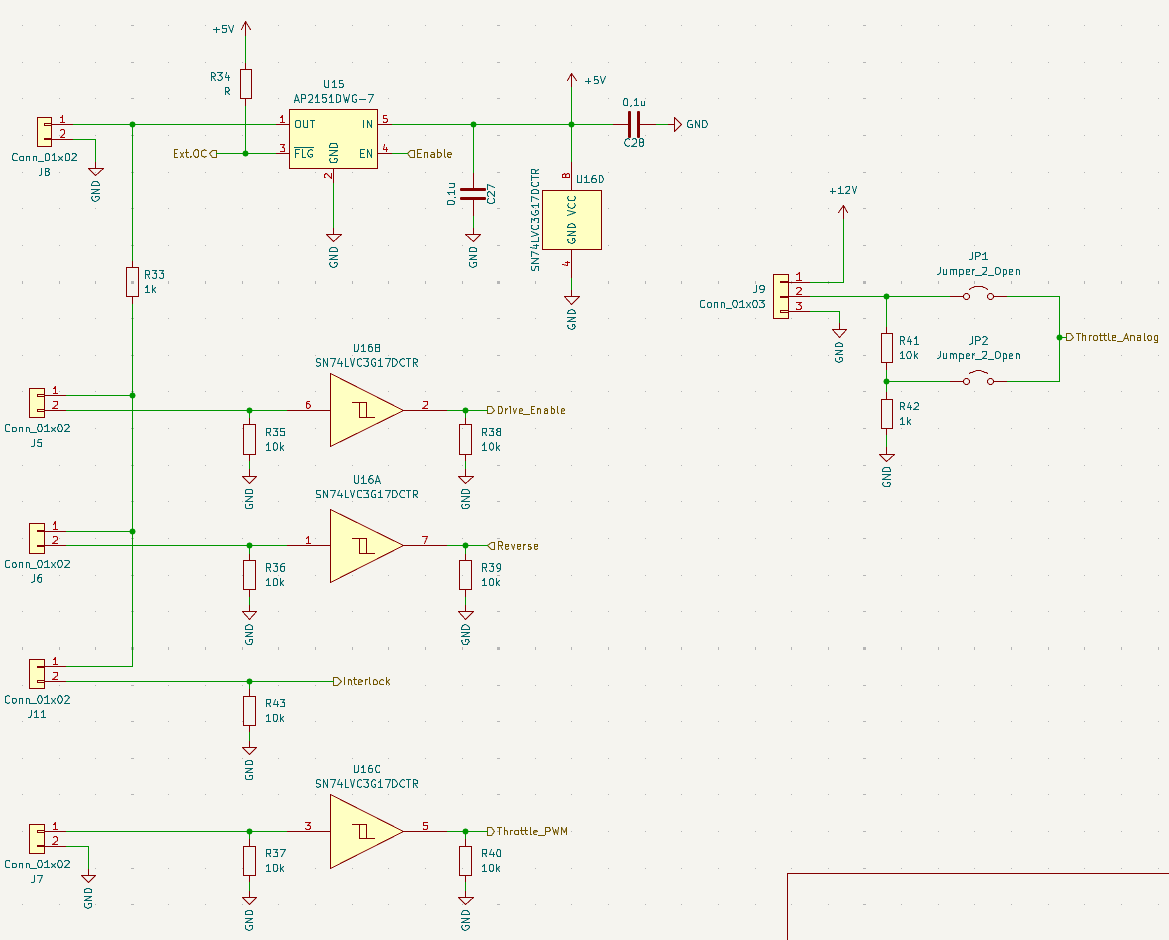
Doing the first layout i also changed the user input -> Removed the USB ... too big of a connector, UART is finde for now -> Added reverse input
All signals except the 12V is secured vie an OC switch. The signals to the controller are schmitttrigger buffered. The Interlock that goes to the shutdown enters the AND-gate and thus does not need a buffer.
Another important part. The connection to the sensors. I opted to buffer the input with a triple-schmitttrigger just to make sure.... - The 5V output must be protected against a shot circuit at all cost. Problems on the 5V line can break the rest of the logic and/or shutdown the controller. For this i use a powerswitch from USB-devices.
U9 turns off when 500mA is exceeded and also can be dis/enabled by the controller. Convenient
Because i have a bunch of them from the 1Hz challenge project.
From left to right:
A zener diode for safety, and a RC-filter. This is useful to filter fast spikes or allow short OC´s .... lets keep the values open for now and see at the first prototype. Also i decouple the input.
The amplifier. I want to get to a trigger voltage of ~4V The shunt (which is the weakest link in the chain) is 3W max -> ~17A = 170mV 4V/170mV -> A=23 Using 22k and 1k from the E24 line we get exactly 23 ... convenient
Shutdown trigger. The moment the voltage from the amp is above V-, it triggers. Unfortunately, getting the reference voltage precicely is not (cheaply) possible. i opted for the 3,98V ... close enough. So the shutdown threshold is a bit below 17A ... ok
The flipflop .... so you can use a opamp as a RS flipflop ... nice When the shutdown is high, the flipflop will output a LOW signal ... so a active low fault ..... This can be reset by a high-flank on the reset input ....
This feeds into the Shutdown lane which is just a bunch of AND-gates.
First gate outputs high when the enable and fault is high. The other 3 gates forward the highside signals, but only if the first one is also HIGH.
Fault active or Enable LOW = no signals to the driver = no switching of the high side fet´s = no output power.
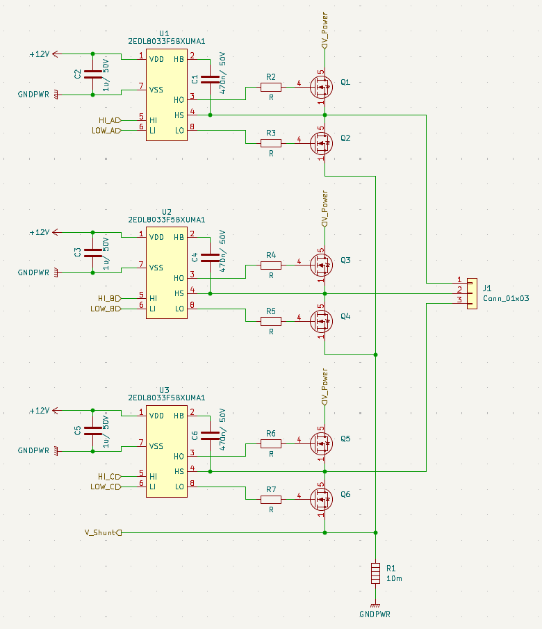
As the main switches i opted for an BSC110N06NS3GATMA1 from infineon
60V VDS max, 30A seems promising enough. Also my plan is to cool if on the bottom side of the PCB and those things have a massive drain-pad. 10mOhm and 50W loss max should be enough to play with. We will see.
Qg ~ 80nC, ton ~60ns
-> Idrv ~ (80/60)x2 = 2A
-> Rg = 6Ohm @12V
Note: you can always change the gate resistance if necessary
-
Also from infineon the driver: 2EDL8033F5BXUMA1
This one can deliver 3A, so it should be OK with the max 2A.
Boot capacitance is said to be 10x input capacitance
-> Cboot = 10x1,5nF = 15nF
-> Opted for 470nF for easier supply
-
Current shunt is a 10mOhm/3W type
Simply because i somehow have a reel of those things .....
15A max -> 2,24W max .... yeah should be ok. 15A is an absolute max anyway ... will be more around 10A so it´ll be fine
Supply voltages in the front, controller in the middle, Power stage and sensors on the output side.
However i added a over-current and a shutdown block in the middle.
The thought is that if i force the HIGH-side mosfet low eg. off, i wont be able to do anything with the motor except maybe braking.
Thus in a overcurrent event, or when i pull the enable, the motor will stop producing torque no matter what.
Also the Drive enable ... a key or emergency off switch will be directly connected to the shutdown. (Drive_Enable and Enable_PWR will be directly connected, the µC will only be able to read the signal)
Drive_Enable = Low then means shutdown of the output stage via hardware. So no fear of acceleration in case of software bugs.
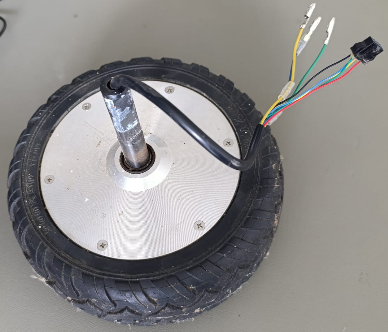
Before i can do anything, lets find out what we are dealing with.
These (propably chinese) hubmotors dont have any useful marking that would let us find a datasheet or anything so we need to make some assumptions.
The one i got has a 36V battery. Appearently these things run around 200-400W (thanks google). So lets take 400W max. = 11A + reserve = 15A
The connector is a 5pin with red/black and 3 colors. Im about 80% certain it is 3 hall-sensors. I always assumed these things needed a more precise position sensor..... Appearently this is accurate enough for the usecase.
So lets summarize, our controller will have: Vmax: 36-38V Imax: 15A 5V external for sensors

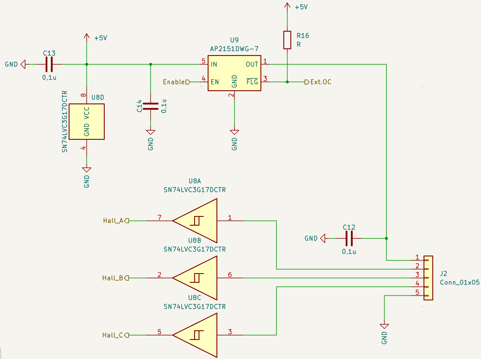 Another important part. The connection to the sensors.
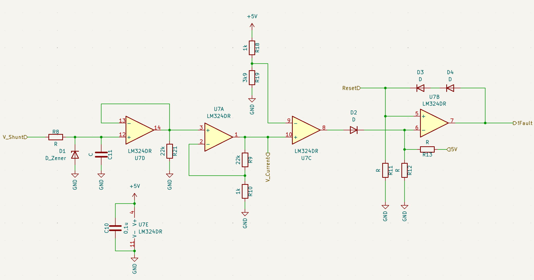


 These (propably chinese) hubmotors dont have any useful marking that would let us find a datasheet or anything so we need to make some assumptions.