We start the PCB assembly process by connecting the two CON20 female header pins on PICO's Footprint from the bottom side of the board.
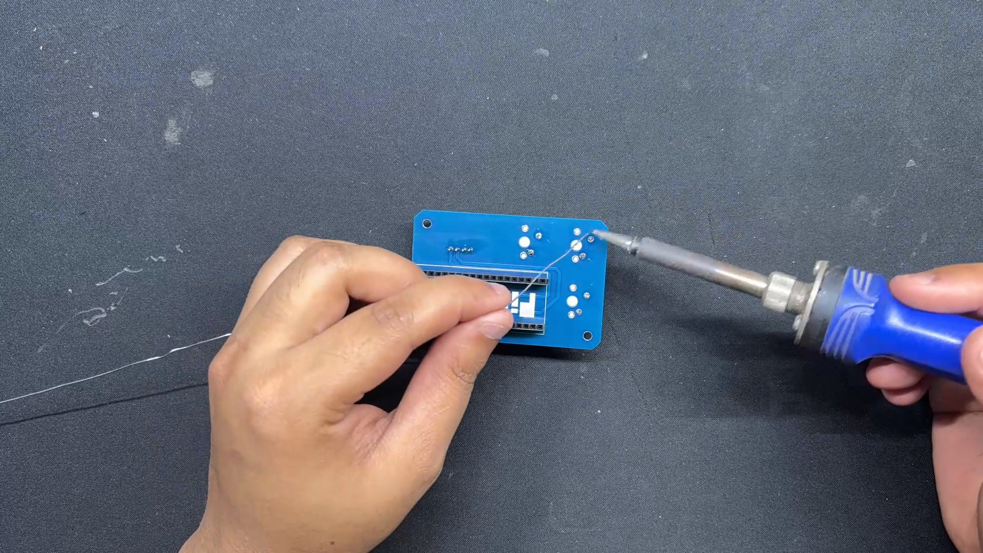
Turning the board over, we use a soldering iron to solder the connector pads from the top side.
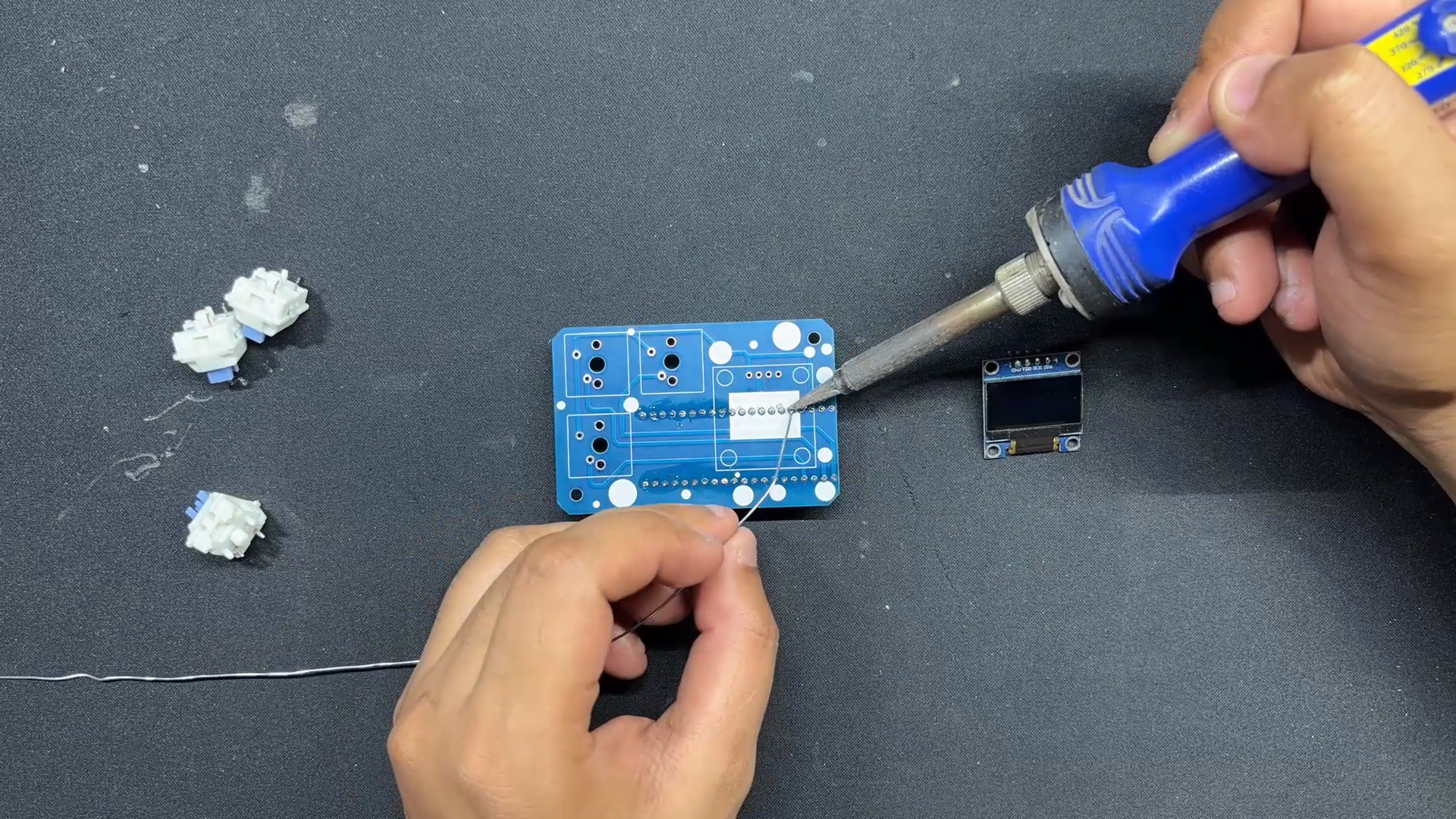
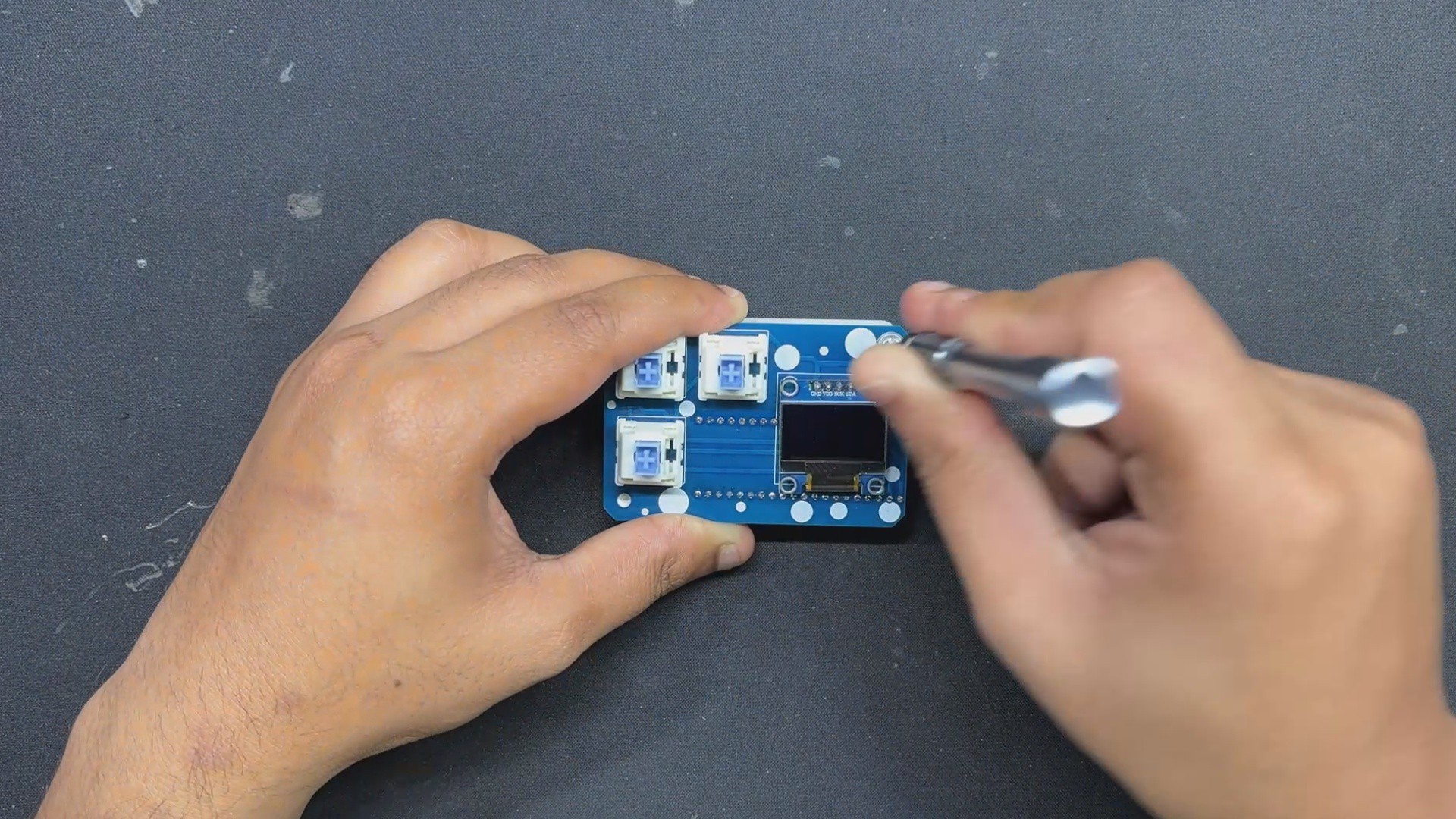
Next, from the top side of the PCB, we place the SSD1306 OLED, followed by the three mechanical switches.
We solder the switch and OLED pins from the bottom of the PCB.
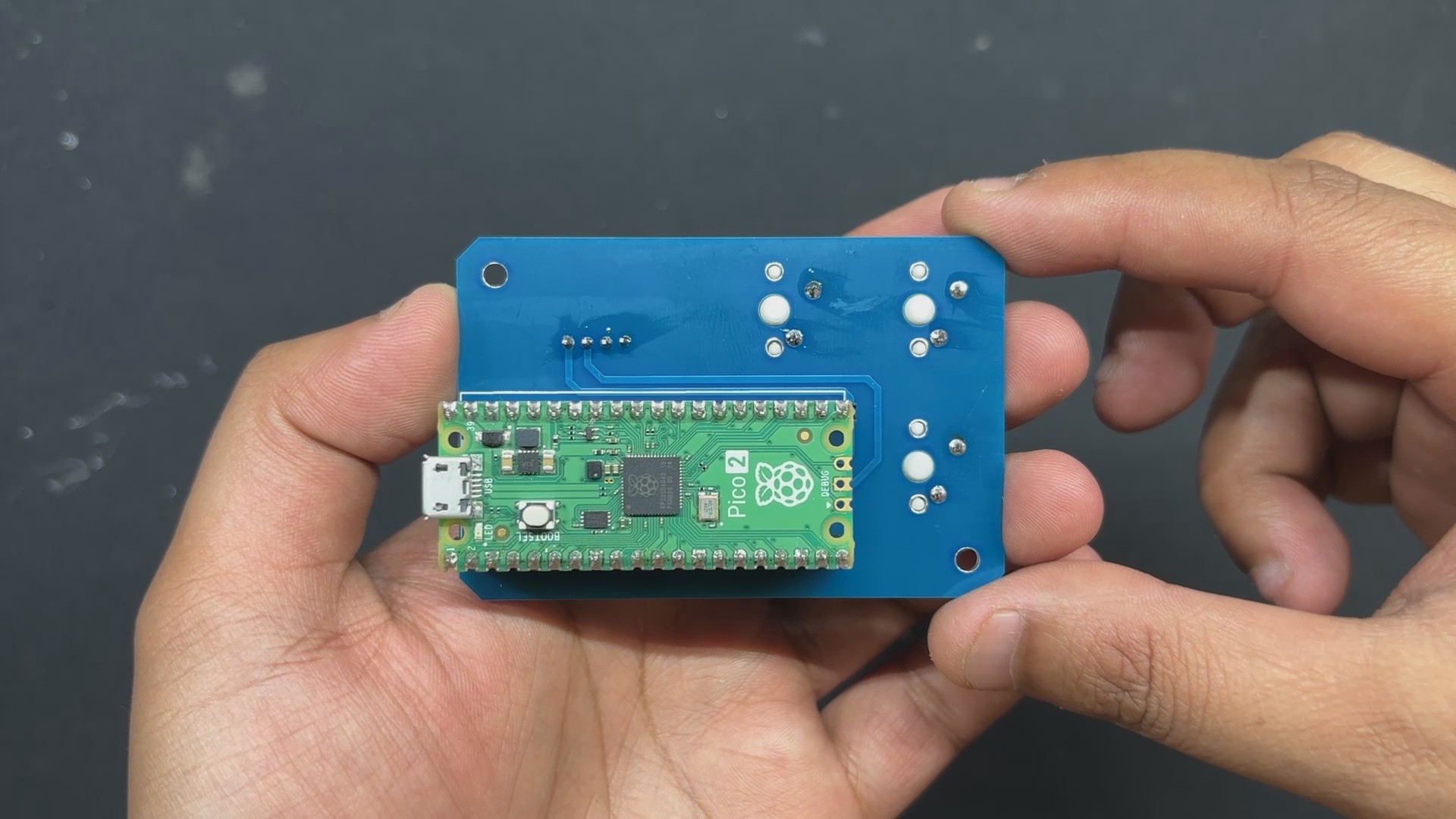
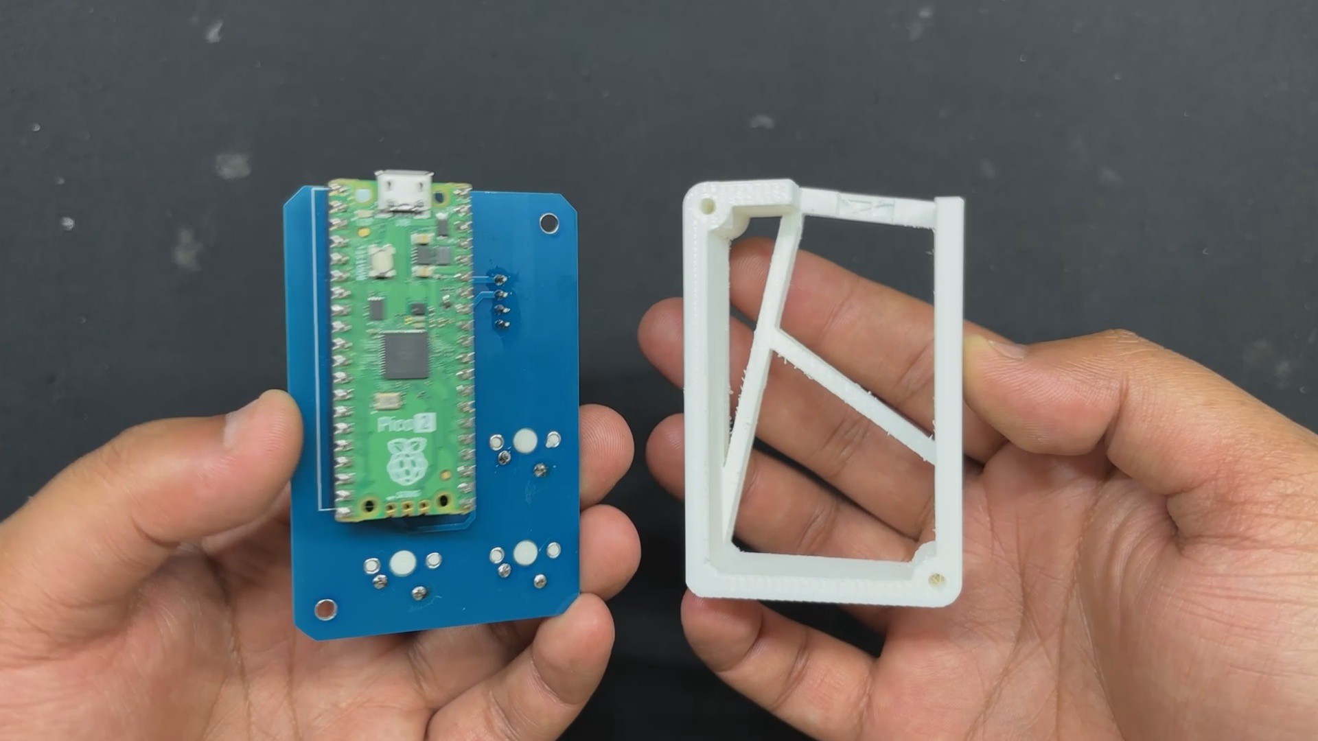
Finally, we install the PICO over the CON20 Header pin connectors.
The PCB assembly has been completed.
2
FINAL ASSEMBLY
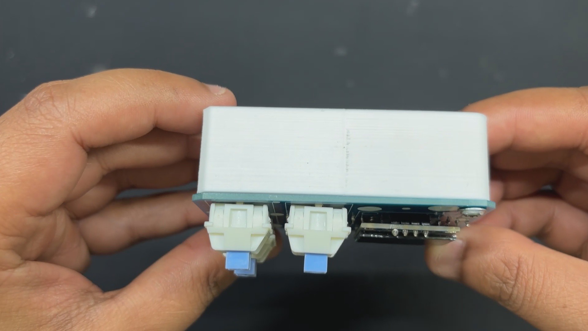
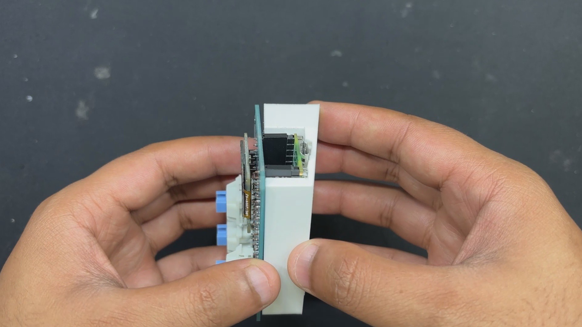
After completing the PCB assembly, we begin the final assembly process, which begins with placing the Circuit over the 3D printed frame and then securing both of them with two M2 screws each.
We added keycaps over the mechanical switches as a finishing touch, which completed the assembly process.
3
CODE
This was the code we used in this project and it's a simple one.
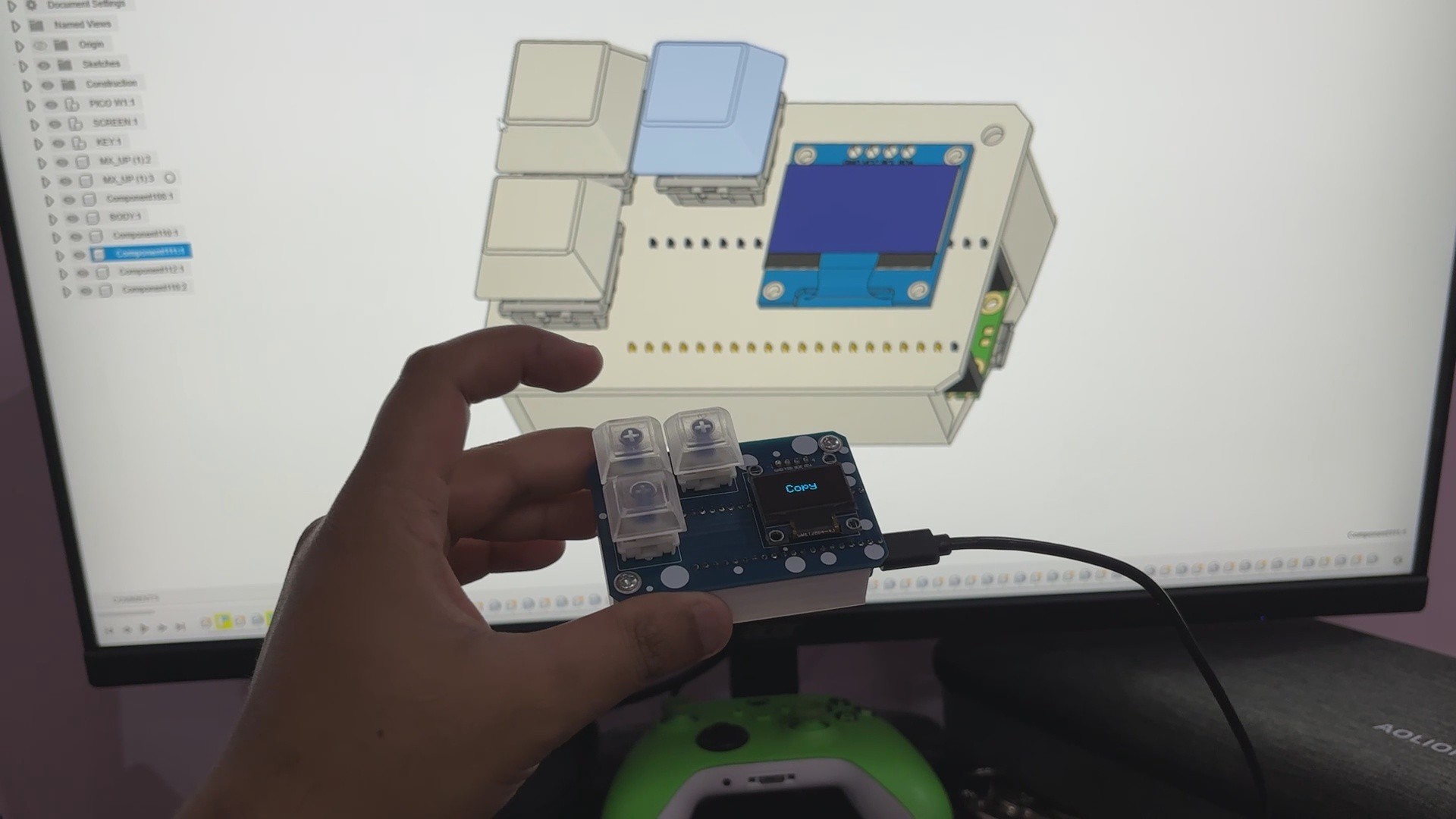
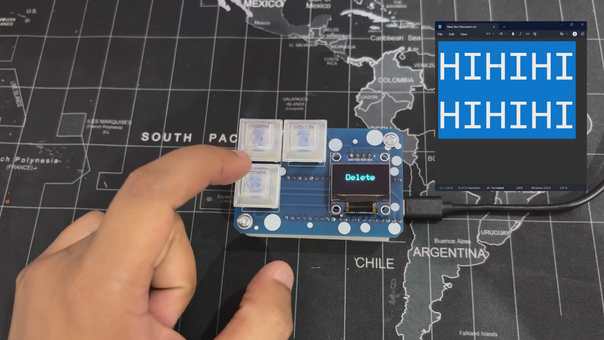
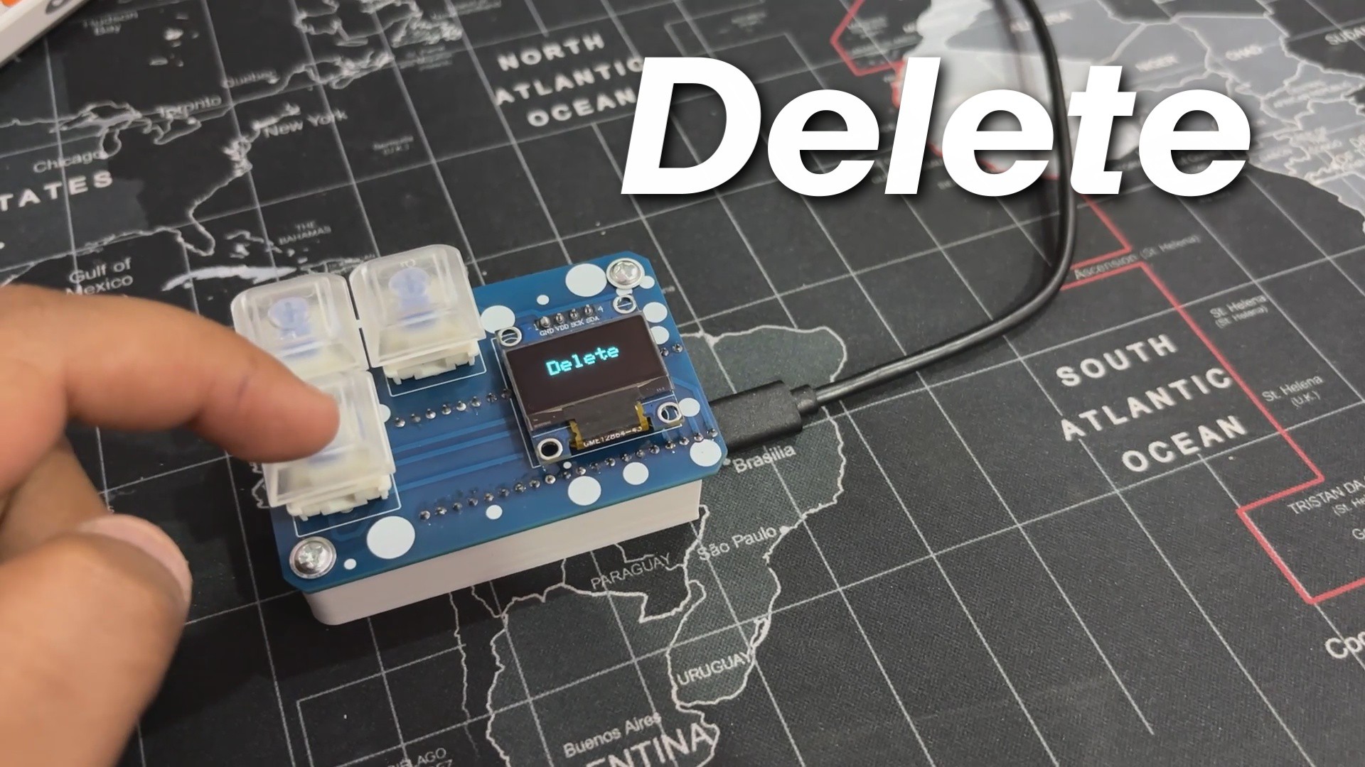
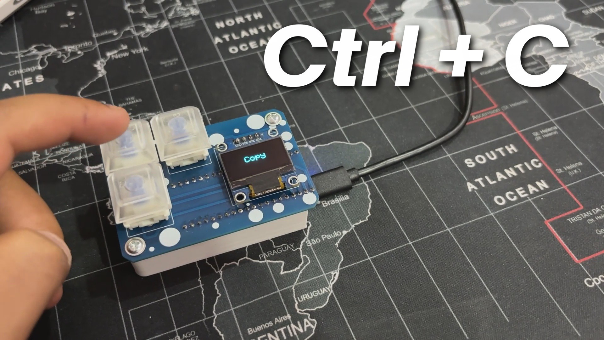
This tiny yet practical build culminated in a macropad capable of performing copy, paste, and delete commands. When you push the copy button, the OLED screen will confirm your action. The paste button allows for seamless pasting, while the delete button provides instant removal functionality. Simple, efficient, and designed for simplified input.
Using this Macropad, I was able to use my preferred design software, Fusion 360, without having to press the Control plus C button; instead, I simply pressed one button to copy and another to paste, and things became slightly easier.
Overall, this project is completed and requires no revisions.
Special thanks to HQ NextPCB for providing components that I've used in this project; check them out for getting all sorts of PCB or PCBA-related services for less cost.
Thanks for reaching this far, and I will be back with a new project soon
 Arnov Sharma
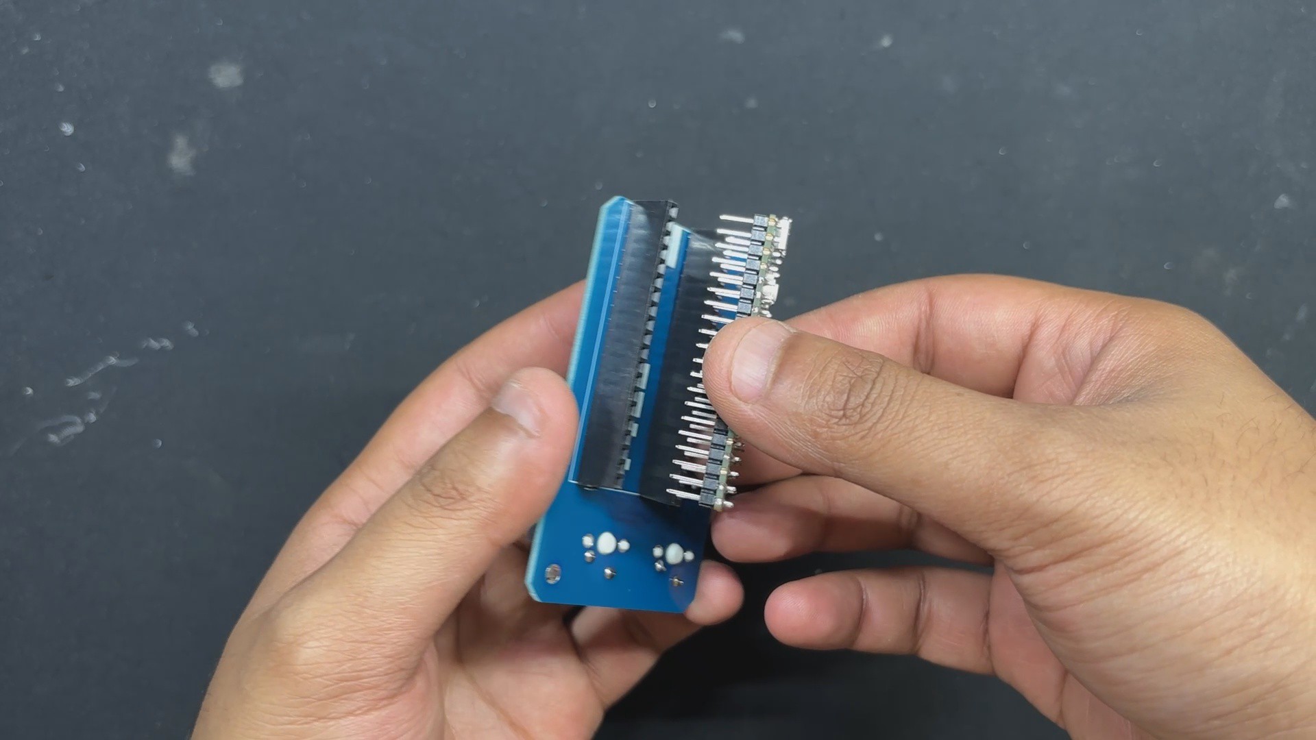


Discussions
Become a Hackaday.io Member
Create an account to leave a comment. Already have an account? Log In.