Close
0%
0%

MACROPAD Pi

A three-button Macropad powered by Raspberry Pi PICO 2

Similar projects worth following
Greetings everyone and welcome back. here's something useful.

MACROPAD Pi is a three-button Macropad built from scratch and powered by the Raspberry Pi PICO. We're utilizing PICO as an HID device, adding three mechanical switches to it and an OLED screen to perform COPY PASTE and erase commands.

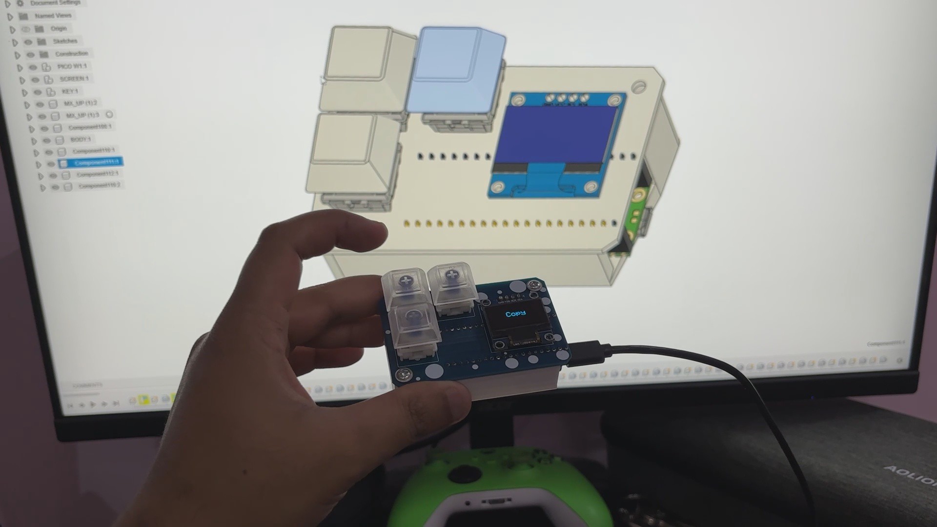
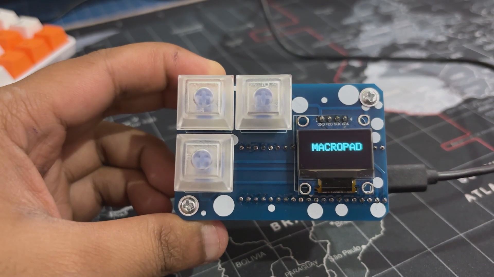
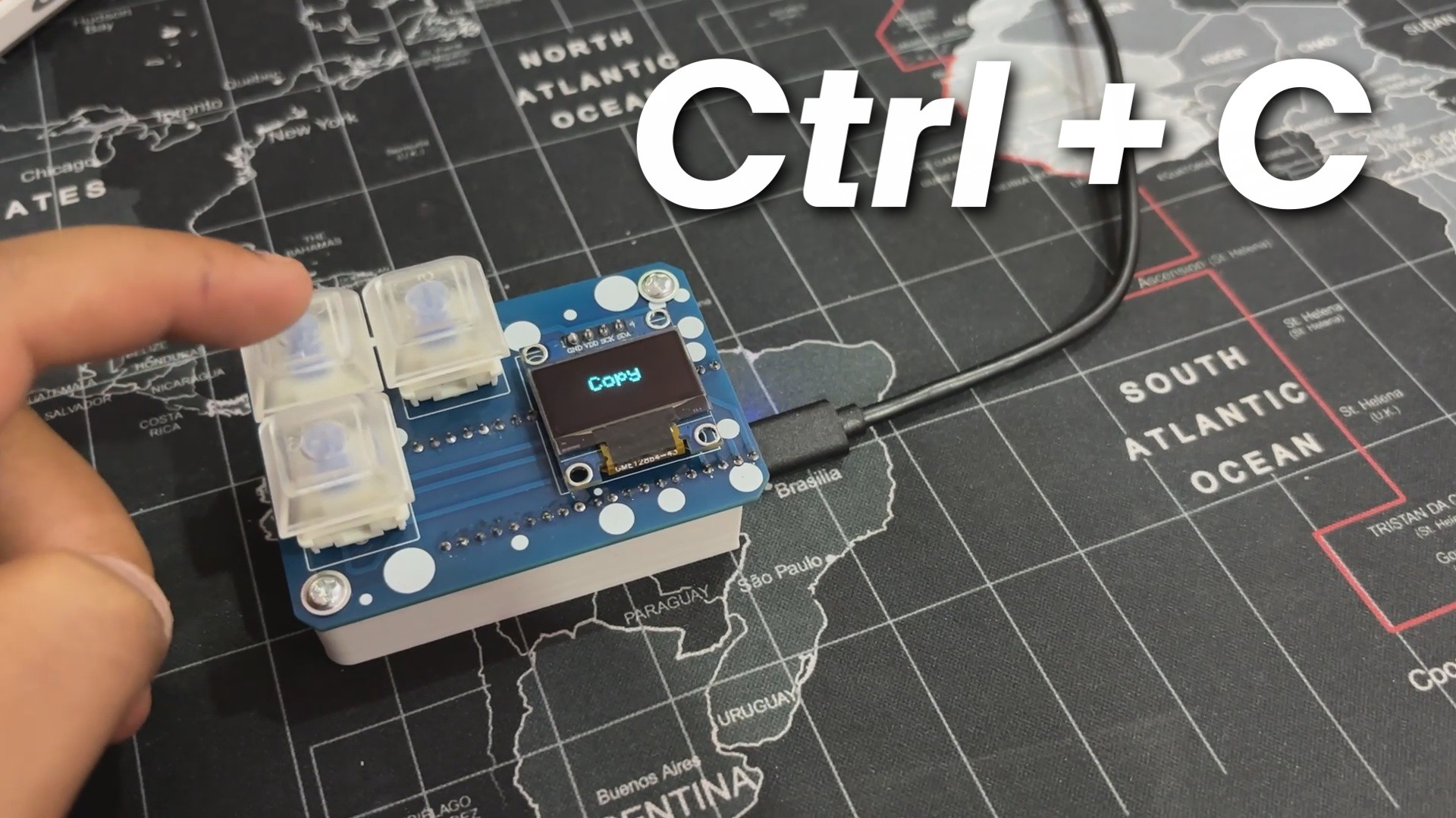
The idea here was to create a super small macropad that I could use while using Fusion360 and other software that required frequent use of the COPY, PASTE, and DELETE commands. We have also incorporated an OLED screen to provide feedback on which command has been selected.

3D Design

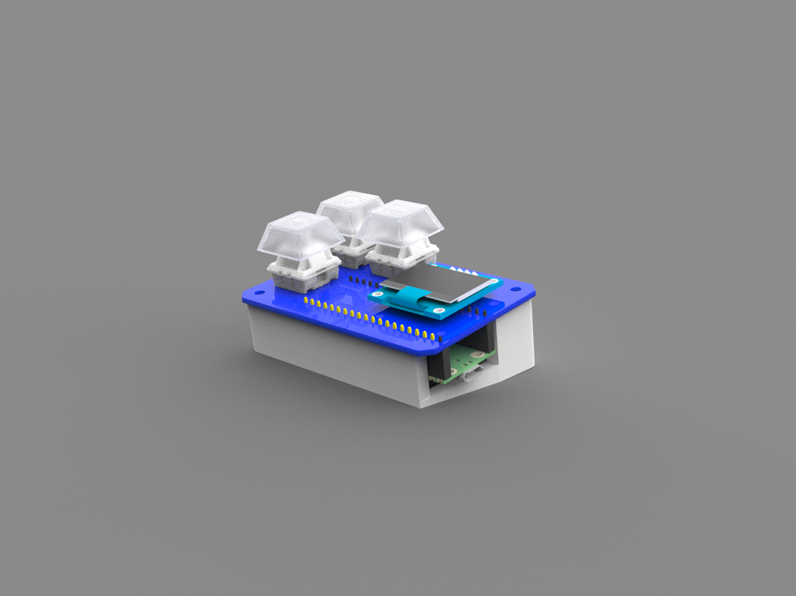
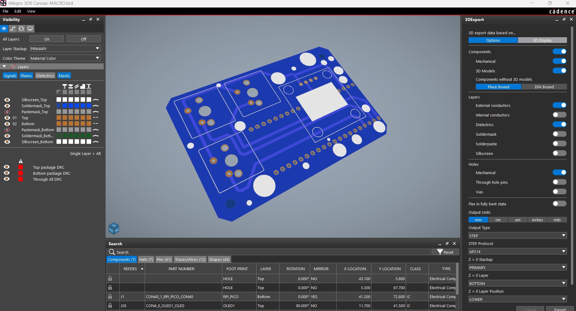
We began the project's 3D design by importing the PICO 3D model, as well as the Switches and OLED screen 3D models.

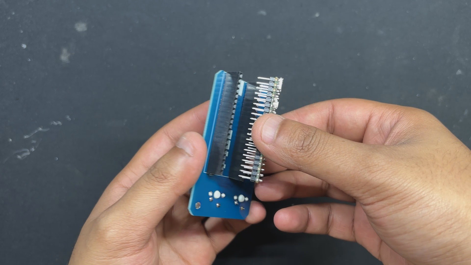
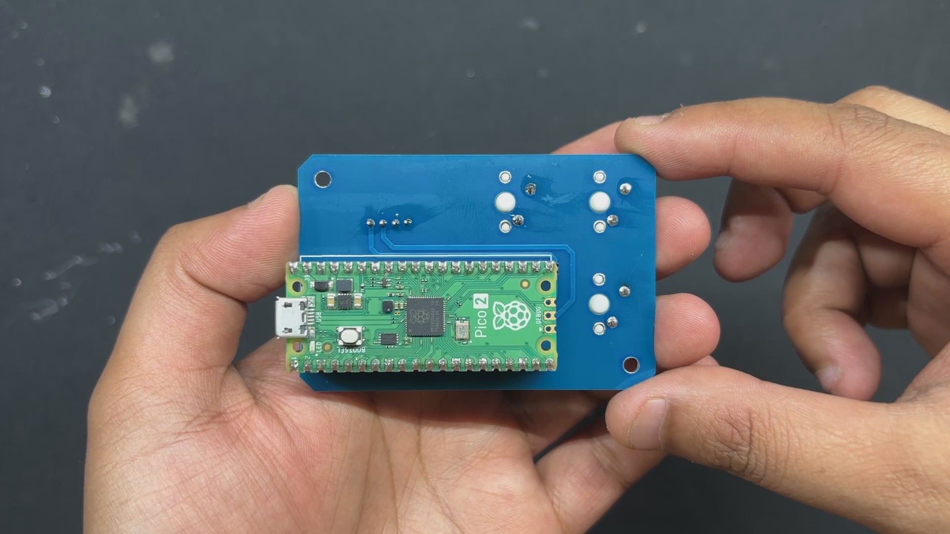
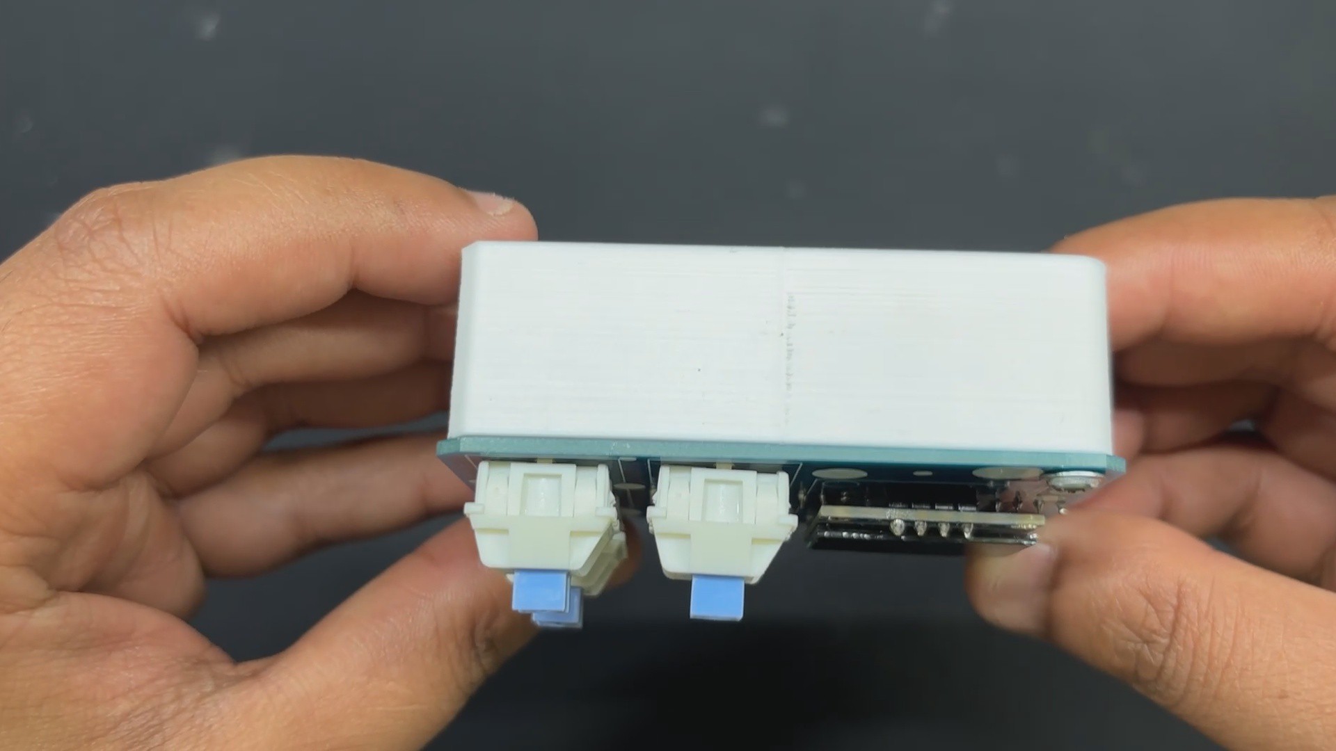
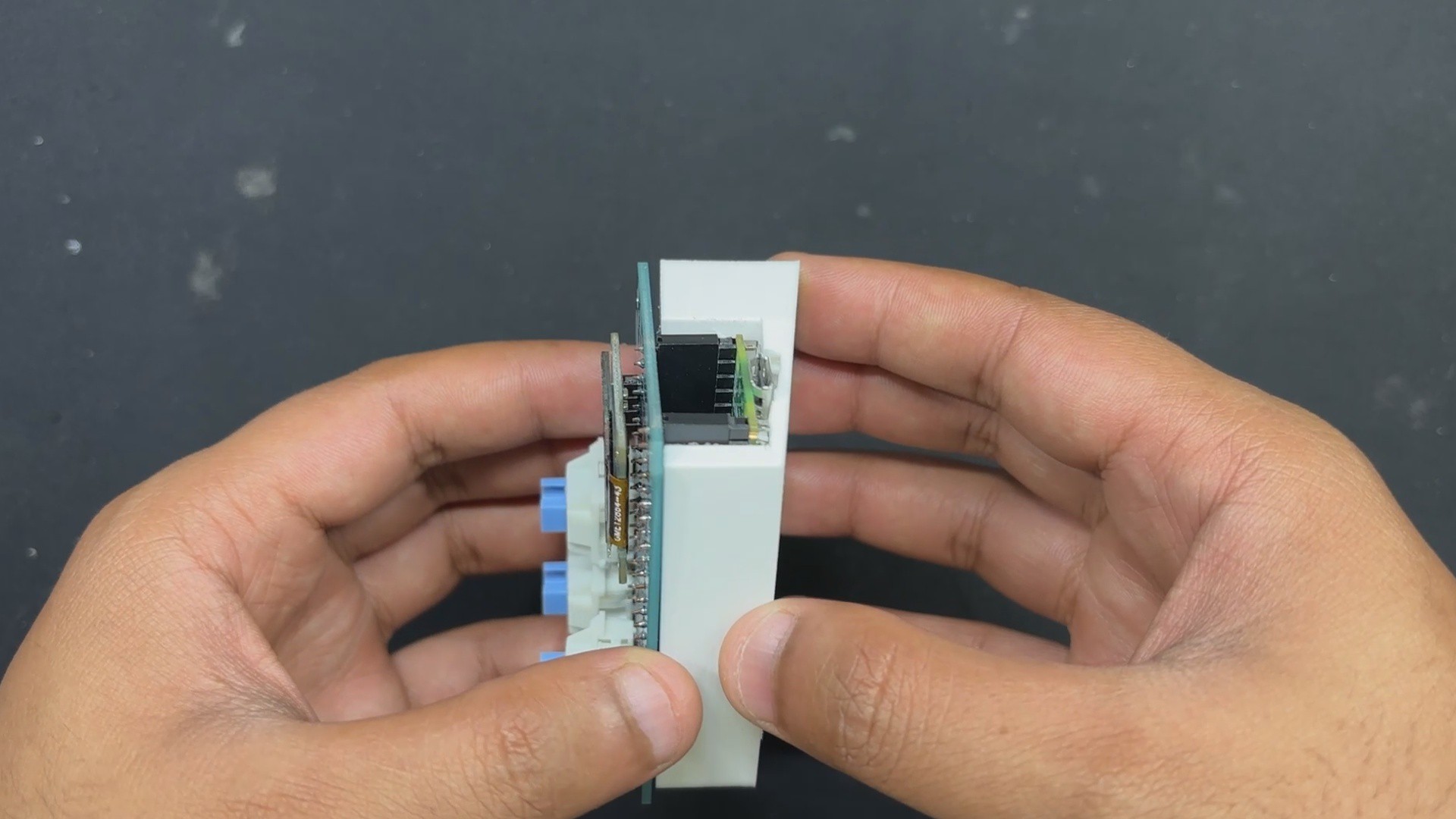
We prepared a PCB with a mechanical switch on one side and a display on the other. We set PICO on the bottom side of the board.

After completing this simple PCB model, we created the frame part that holds the circuit on top. This frame part has a little inclined bottom, allowing the circuit to be put at an angle and lightly tilted as a keyboard.

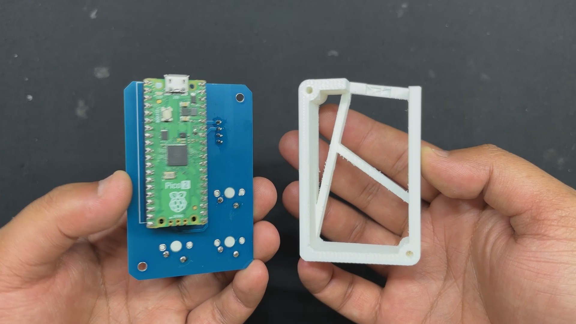
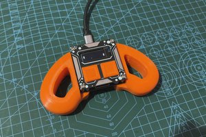
Frame part was finalized and 3D printed with PLA using a 0.4mm nozzle and 0.2mm layer height.

PCB Design

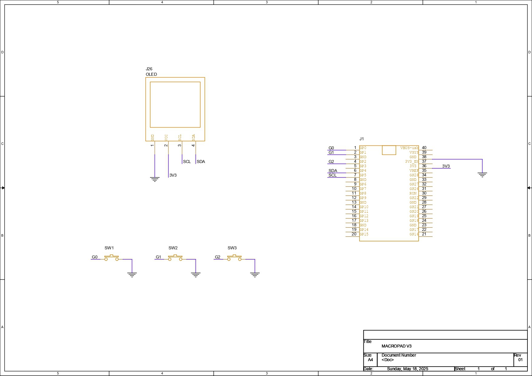
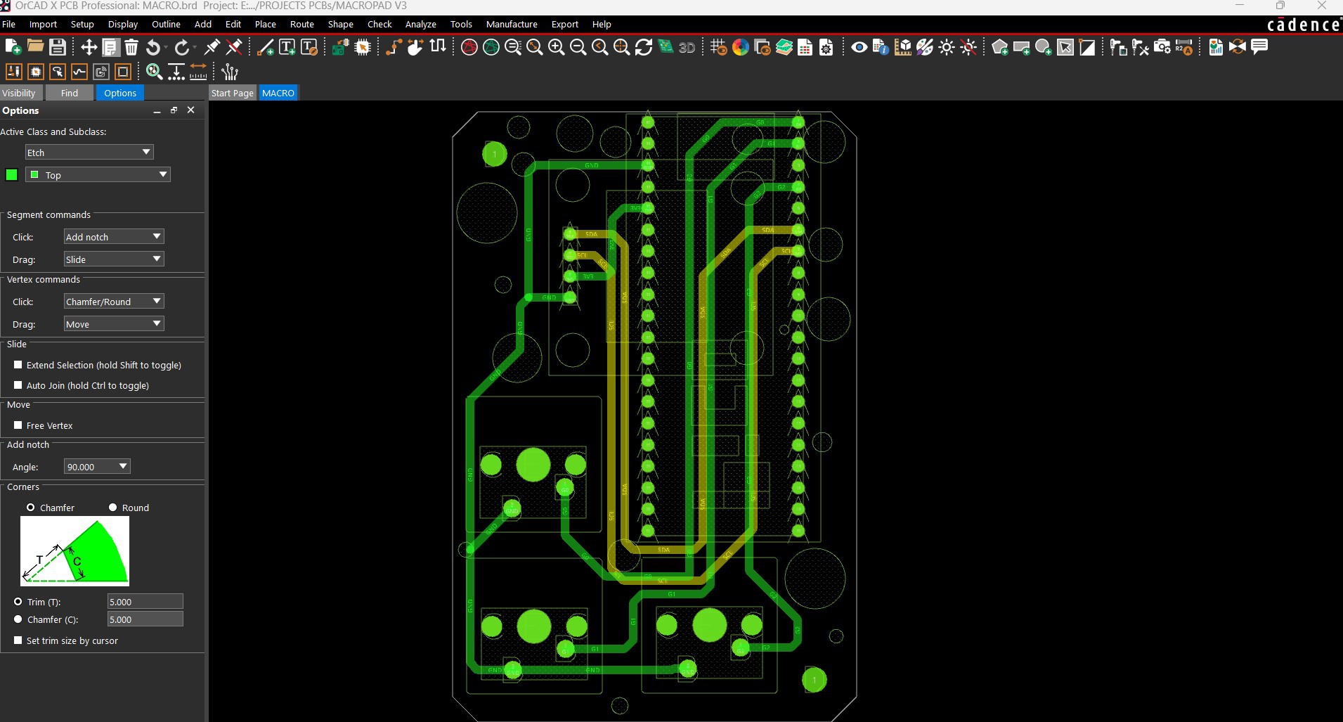
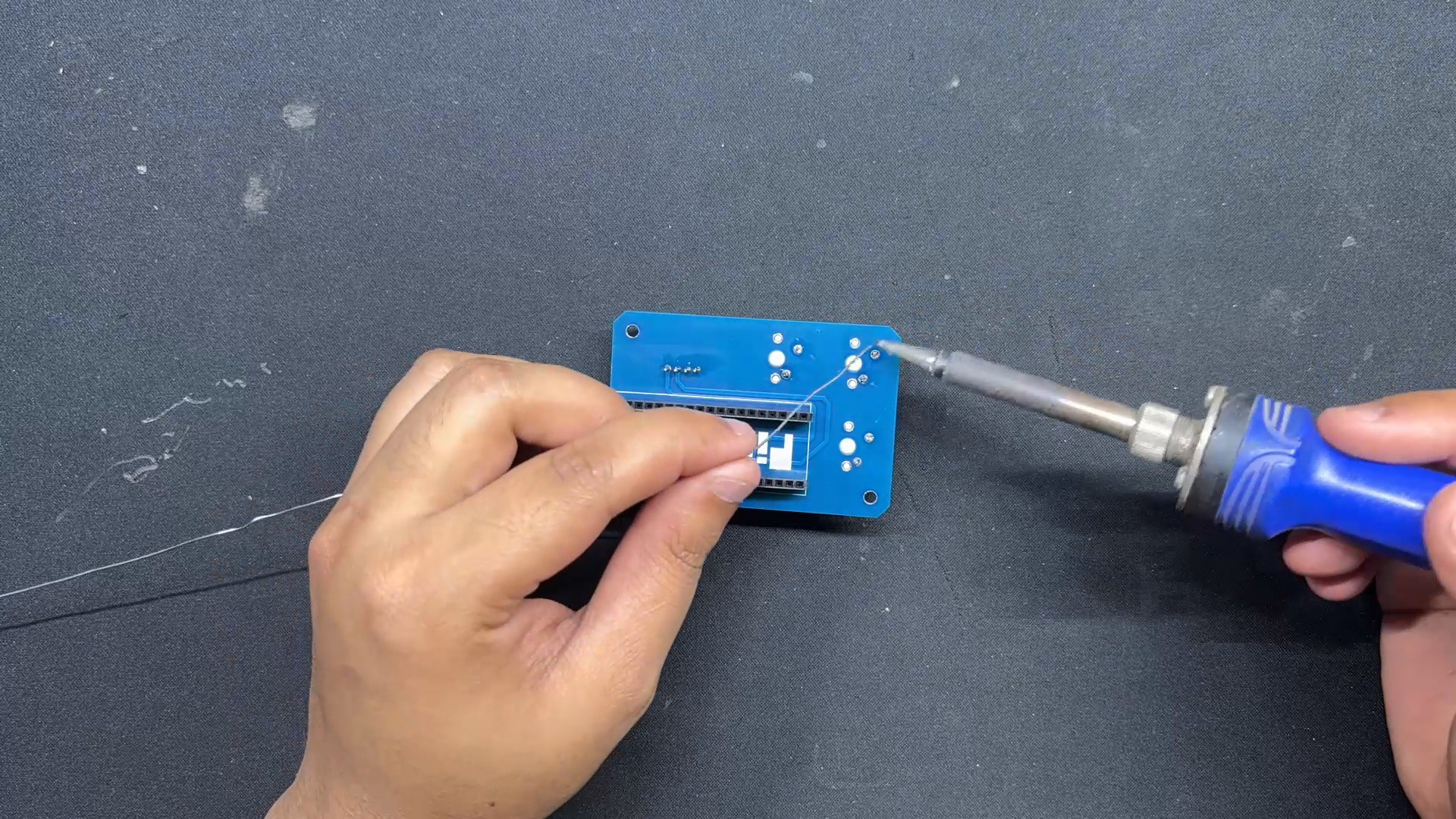
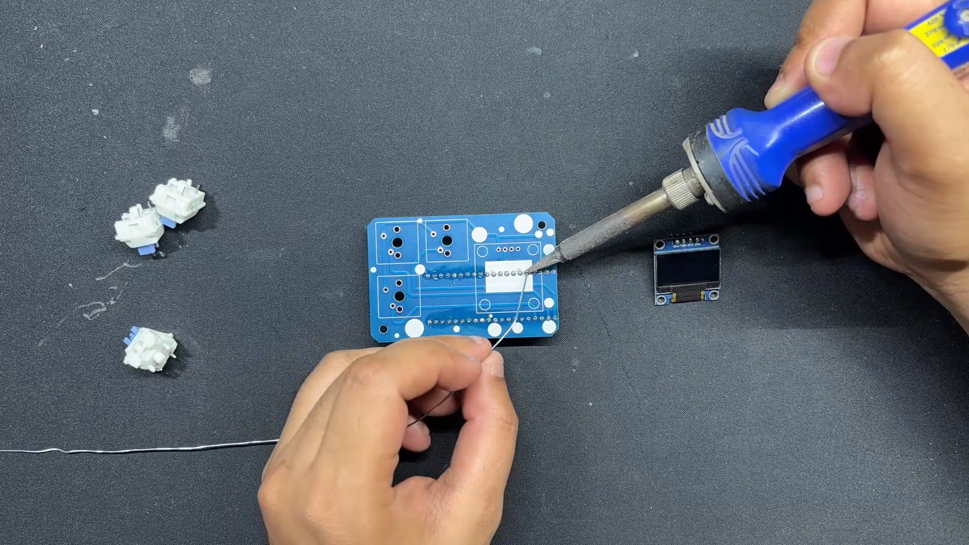
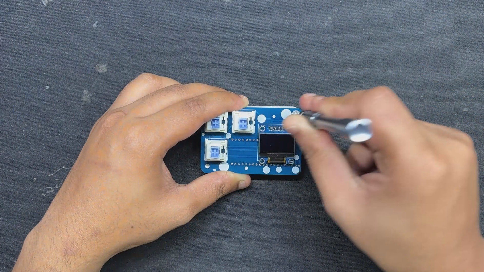
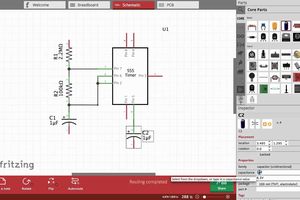
For the schematic of this project, we initially created a small setup consisting of a Raspberry Pi Pico, an SSD1306 OLED screen, and three mechanical switches. We connected the OLED's VCC to the PICO's VBUS pin, GND to GND, the SDA pin to GPIO4, and the SCL pin to GPIO 5. All three switches are connected to GPIO0, GPIO1, and GPIO2.

Using the dimensions from the cad file, we created the PCB layout and the board outline and placed components in their proper locations. PICO 2 is located at the bottom of the board.

NextPCB PCB Service

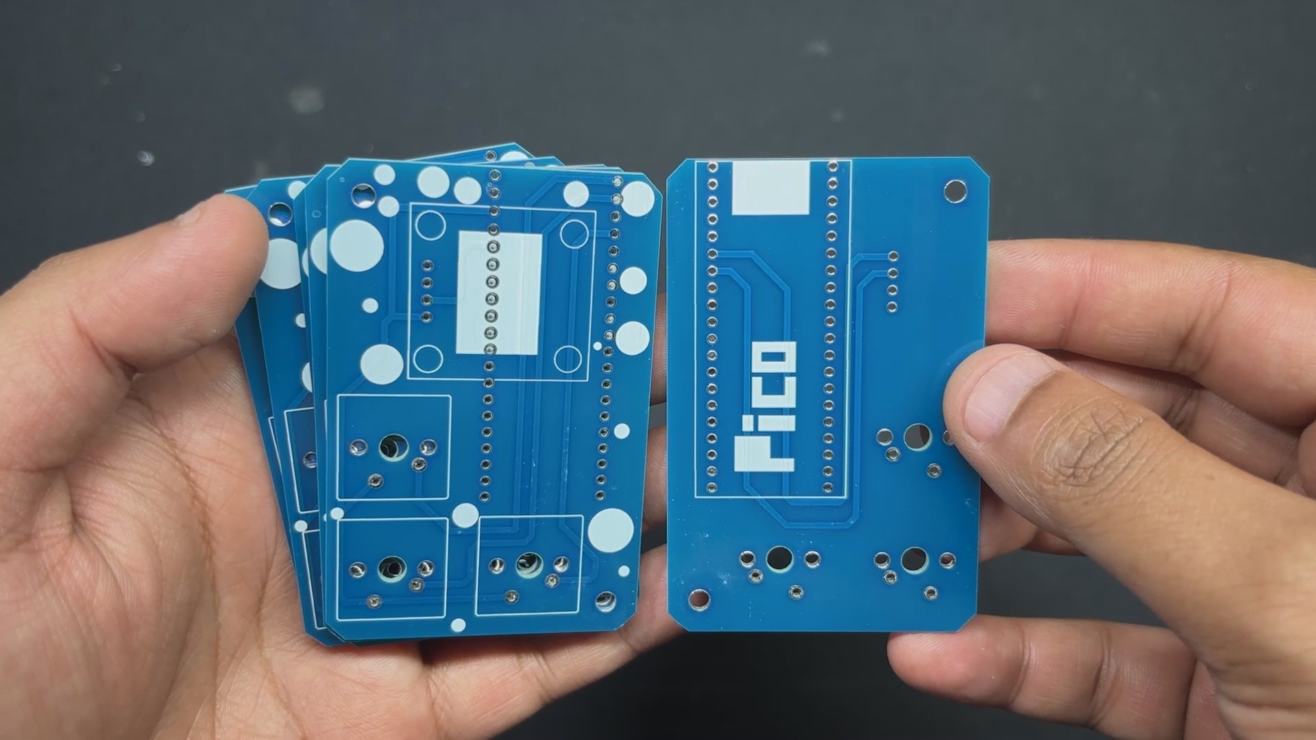
Gerber Data was sent to HQ NextPCB, and an order was place for Blue Soldermask and white silkscreen.

After placing the order, the PCBs were received within a week, and the PCB quality was pretty great.

In addition, I have to bring in HQDFM to you, which helped me a lot through many projects. Huaqiu’s in-house engineers developed the free Design for Manufacturing software, HQDFM, revolutionizing how PCB designers visualize and verify their designs.

Take advantage of NextPCB's Accelerator campaign and get 2 free assembled RP2040-based PCBs for your innovative projects.

https://www.nextpcb.com/blog/rp2040-free-pcba-prototypes-nextpcb-accelerator

This offer covers all costs, including logistics, making it easier and more affordable to bring your ideas to life. SMT services can be expensive, but NextPCB is here to help you overcome that hurdle. Simply share your relevant project, and they'll take care of the rest. Don't miss out on this amazing opportunity to advance your tech creations!

HQDFM: Free Online Gerber Viewer and DFM Analysis Tool

Also, NextPCB has its own Gerber Viewer and DFM analysis software.

Your designs are improved by their HQDFM software (DFM) services. Since I find it annoying to have to wait around for DFM reports from manufacturers, HQDFM is the most efficient method for performing a pre-event self-check.

This is what I see in the online Gerber Viewer. It's decent for a quick look but not entirely clear. For full functionality—like detailed DFM analysis for PCBA—you’ll need to download the desktop software. The web version only offers a basic DFM report.

With comprehensive Design for Manufacture (DFM) analysis features, HQDFM is a free, sophisticated online PCB Gerber file viewer.

With over 15 years of industry experience, it offers valuable insights into advanced manufacturing processes. If you’re looking for reliable PCB services at a budget-friendly price, HQ NextPCB is definitely worth checking out.

macropad v3.rar

x-compressed - 12.85 kB - 07/23/2025 at 07:13

Download

MACROPAD v3 v5.step

step - 20.49 MB - 07/23/2025 at 07:12

Download

MACRO.pdf

Adobe Portable Document Format - 153.22 kB - 07/23/2025 at 07:12

Preview

BODY.3mf

3mf - 54.50 kB - 07/23/2025 at 07:12

Download

  • 1
    PCB ASSEMBLY
    • We start the PCB assembly process by connecting the two CON20 female header pins on PICO's Footprint from the bottom side of the board.
    • Turning the board over, we use a soldering iron to solder the connector pads from the top side.
    • Next, from the top side of the PCB, we place the SSD1306 OLED, followed by the three mechanical switches.
    • We solder the switch and OLED pins from the bottom of the PCB.
    • Finally, we install the PICO over the CON20 Header pin connectors.

    The PCB assembly has been completed.

  • 2
    FINAL ASSEMBLY

    After completing the PCB assembly, we begin the final assembly process, which begins with placing the Circuit over the 3D printed frame and then securing both of them with two M2 screws each.

    We added keycaps over the mechanical switches as a finishing touch, which completed the assembly process.

  • 3
    CODE

    This was the code we used in this project and it's a simple one.

    #include <Wire.h>
    #include <Adafruit_GFX.h>
    #include <Adafruit_SSD1306.h>
    #include <Keyboard.h>
    // Pin Definitions
    #define BUTTON_COPY 0
    #define BUTTON_PASTE 1
    #define BUTTON_DELETE 2
    // OLED Display Config
    #define SCREEN_WIDTH 128
    #define SCREEN_HEIGHT 64
    Adafruit_SSD1306 display(SCREEN_WIDTH, SCREEN_HEIGHT, &Wire, -1);
    // State Tracking
    unsigned long lastActionTime = 0;
    bool showingCommand = false;
    void setup() {
    pinMode(BUTTON_COPY, INPUT_PULLUP);
    pinMode(BUTTON_PASTE, INPUT_PULLUP);
    pinMode(BUTTON_DELETE, INPUT_PULLUP);
    Wire.begin();
    display.begin(SSD1306_SWITCHCAPVCC, 0x3C);
    display.clearDisplay();
    display.setTextColor(SSD1306_WHITE);
    display.display();
    Keyboard.begin();
    showIdle(); // Display "MACROPAD" at startup
    }
    void loop() {
    if (digitalRead(BUTTON_COPY) == LOW) {
    showCommand("Copy");
    Keyboard.press(KEY_LEFT_CTRL);
    Keyboard.press('c');
    delay(100);
    Keyboard.releaseAll();
    lastActionTime = millis();
    showingCommand = true;
    }
    else if (digitalRead(BUTTON_PASTE) == LOW) {
    showCommand("Paste");
    Keyboard.press(KEY_LEFT_CTRL);
    Keyboard.press('v');
    delay(100);
    Keyboard.releaseAll();
    lastActionTime = millis();
    showingCommand = true;
    }
    else if (digitalRead(BUTTON_DELETE) == LOW) {
    showCommand("Delete");
    Keyboard.press(KEY_DELETE);
    delay(100);
    Keyboard.releaseAll();
    lastActionTime = millis();
    showingCommand = true;
    }
    // Check if 5 seconds have passed since last action
    if (showingCommand && millis() - lastActionTime > 5000) {
    showIdle();
    showingCommand = false;
    }
    delay(100); // Loop throttle + debounce
    }
    void showCommand(String command) {
    display.clearDisplay();
    display.setTextSize(2);
    int16_t x = (SCREEN_WIDTH - command.length() * 12) / 2;
    display.setCursor(max(0, x), 20);
    display.println(command);
    display.display();
    }
    void showIdle() {
    display.clearDisplay();
    display.setTextSize(2);
    display.setCursor(20, 20);
    display.println("MACROPAD");
    display.display();
    }

View all 4 instructions

Enjoy this project?

Share

Discussions

Similar Projects

Does this project spark your interest?

Become a member to follow this project and never miss any updates