 Arnov Sharma


Unlike the full-fledged Raspberry Pi that comes with operating systems and multimedia support, the Pico is a microcontroller. That means no Linux, no built-in graphics stack, and no luxury of high-level emulation frameworks. Everything—from display handling to sound generation and ROM loading—had to be engineered from scratch. And that’s exactly what makes this build special. However, we are not really building the emulator from scratch; we are using an existing Pico GB project repository. All the circuitry has been built from scratch.
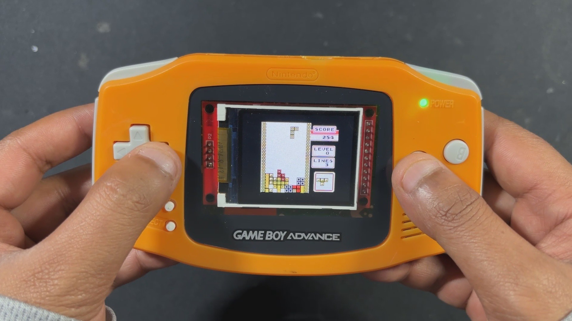
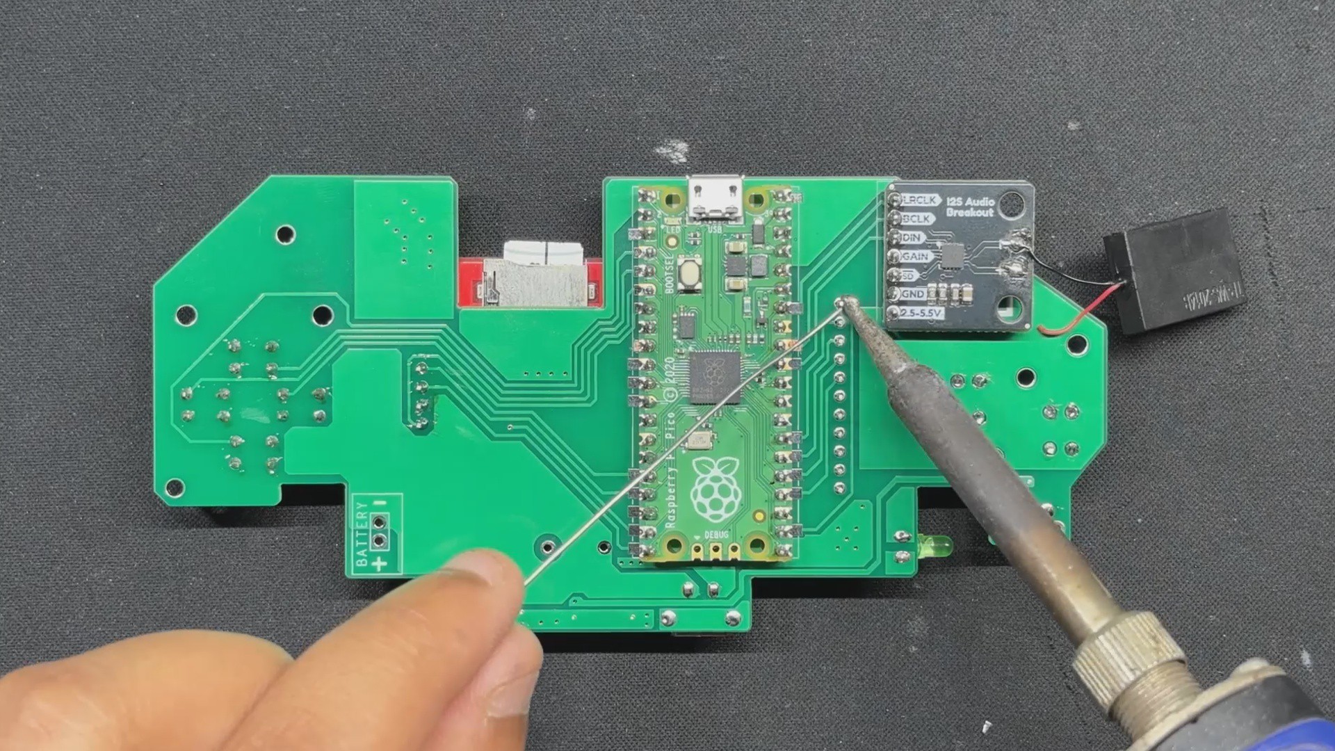
PiBoy Advance runs Game Boy ROMs directly from an SD card, displays them on an ILI9225 screen, and even outputs sound using a MAX98357 I2S Module.
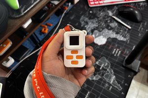
The shell used in this project was arranged from a local marketplace in my city, which is the Lajpat Rai market. It's one of the biggest electronics marketplaces in India; it's in front of Red Fort, New Delhi, and here you can find a bunch of old retro games and related stuff. I even got an OLED PSP and PS2 from here, which I will be using in a future project.
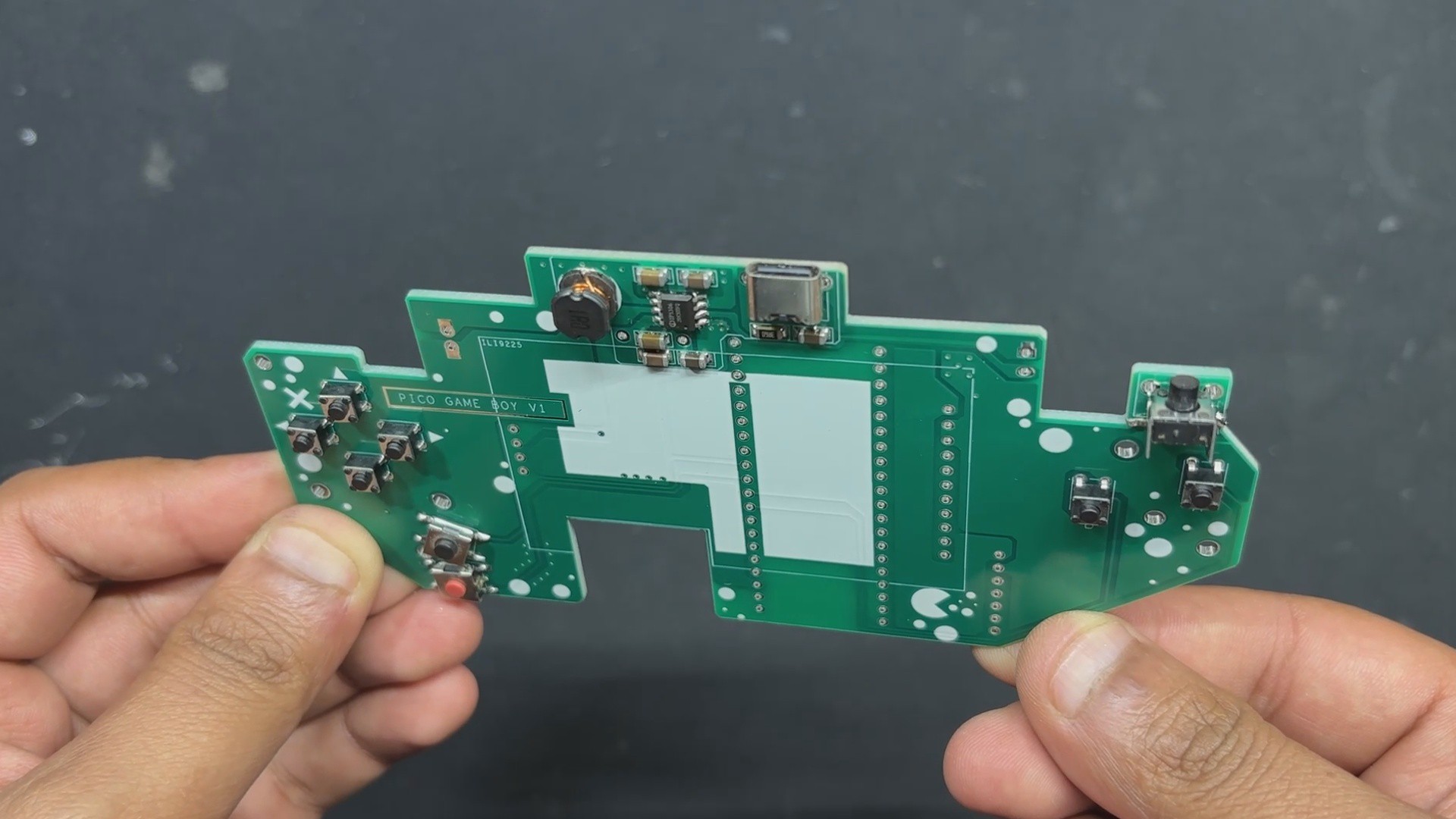
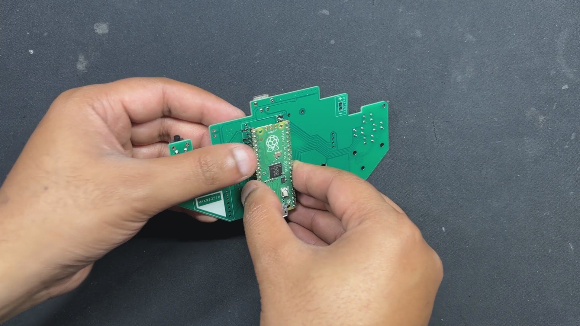
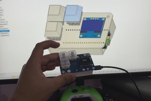
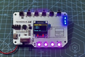
By following the PICO GB pinout info found on their GitHub page, I was able to make a simple circuit that houses the PICO display and the sound module together along with buttons for controls.
Additionally, because we are making a handheld device, we had to provide a stable power source, so we added a power management circuit in our setup, which uses a LiPo cell to provide power to our PICO setup.
This article covers the complete build process of the PiBoy Advance project, so let's get started with the build.
Hardware


For our Game Boy Project, we're using the Pico-GB repository created by YouMakeTech; this version was a fork of the RP2040-GB Game Boy (DMG) emulator from deltabeard. Here the PICO serves as the brain of the project. I did try to use PICO 2 and even PICO W, but this only works with the PICO RP2040.
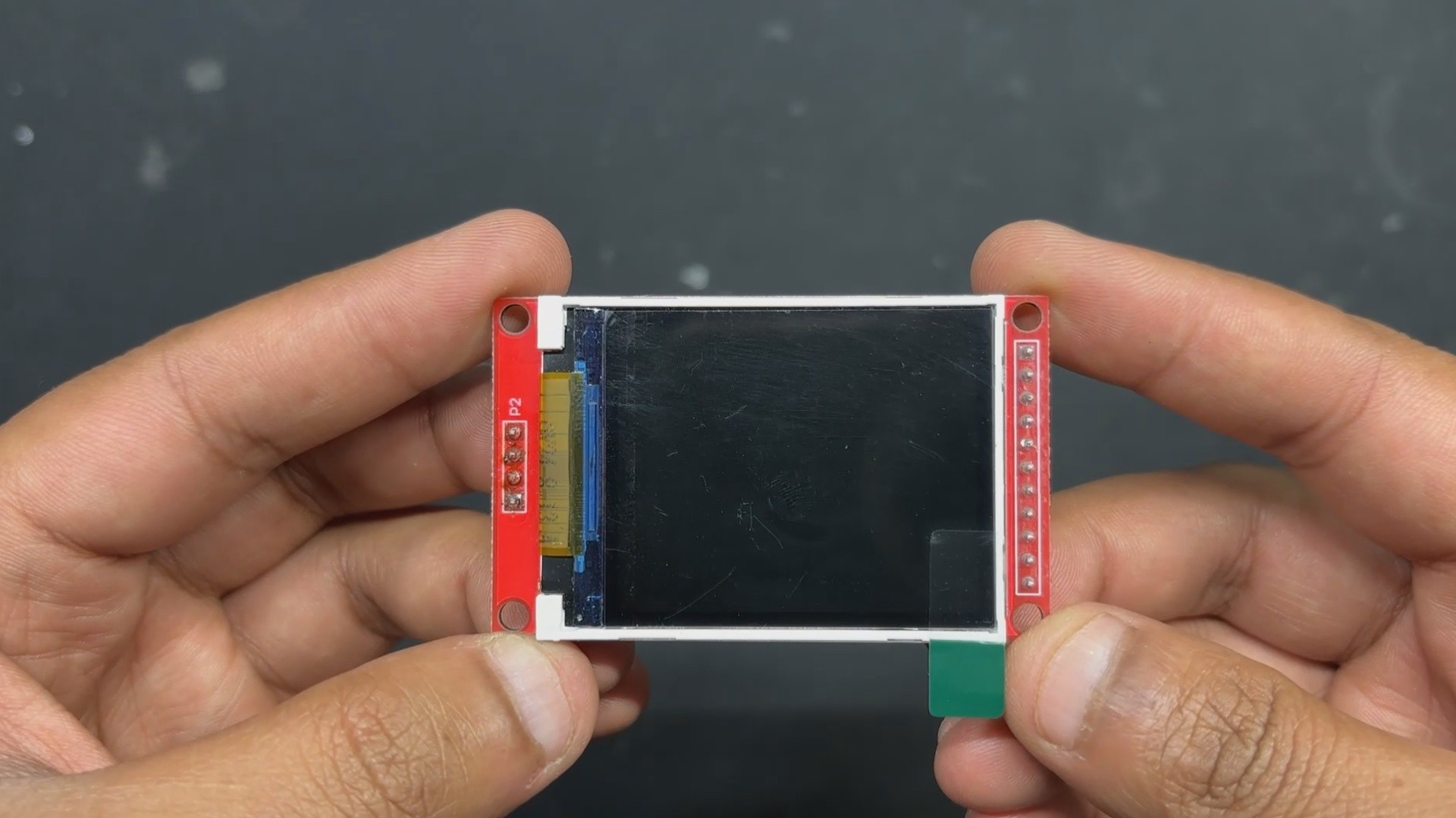
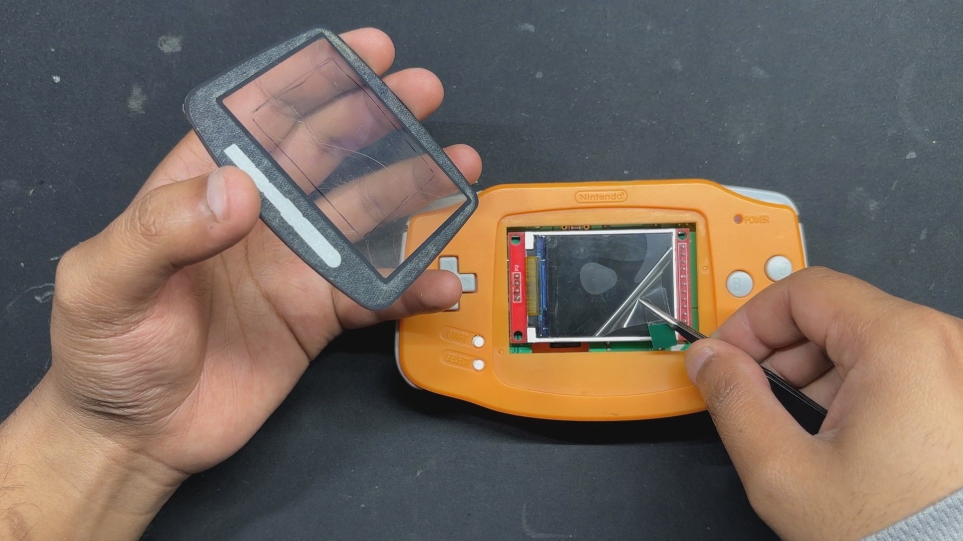
For the display, we have to use the ILI9225 display, which runs more than 70 fps, which is insane. The original DMG project didn't support audio out, so youMakeTech modified the original file and added a few key functions that include I2S sound, meaning we had to use an I2S amplifier module. For this, we chose the MAX98357 audio module that is connected to a small form factor 1W speaker, which will provide audio output for our device. a small fun fact, this small 1W Speaker is harvested from DF ROBOT'S unihiker k10 Dev board.
Game Boy Advance Shell

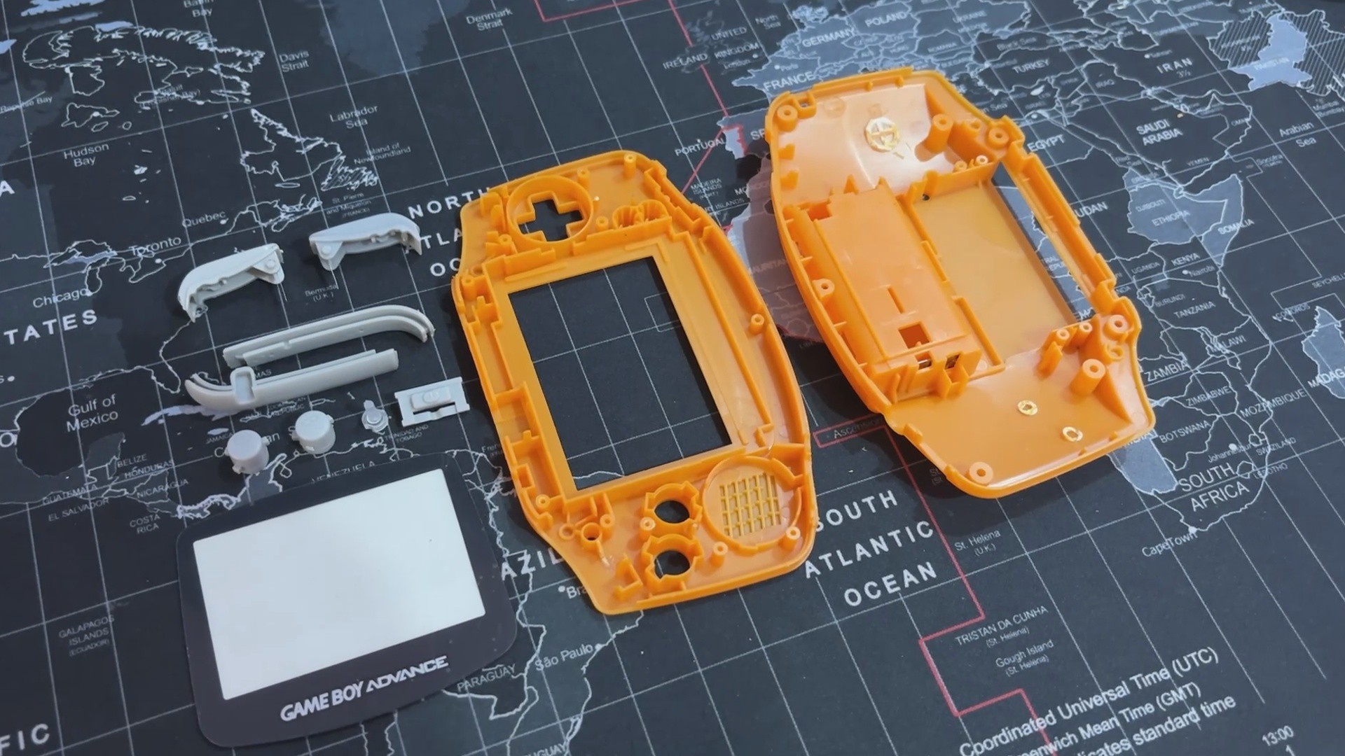
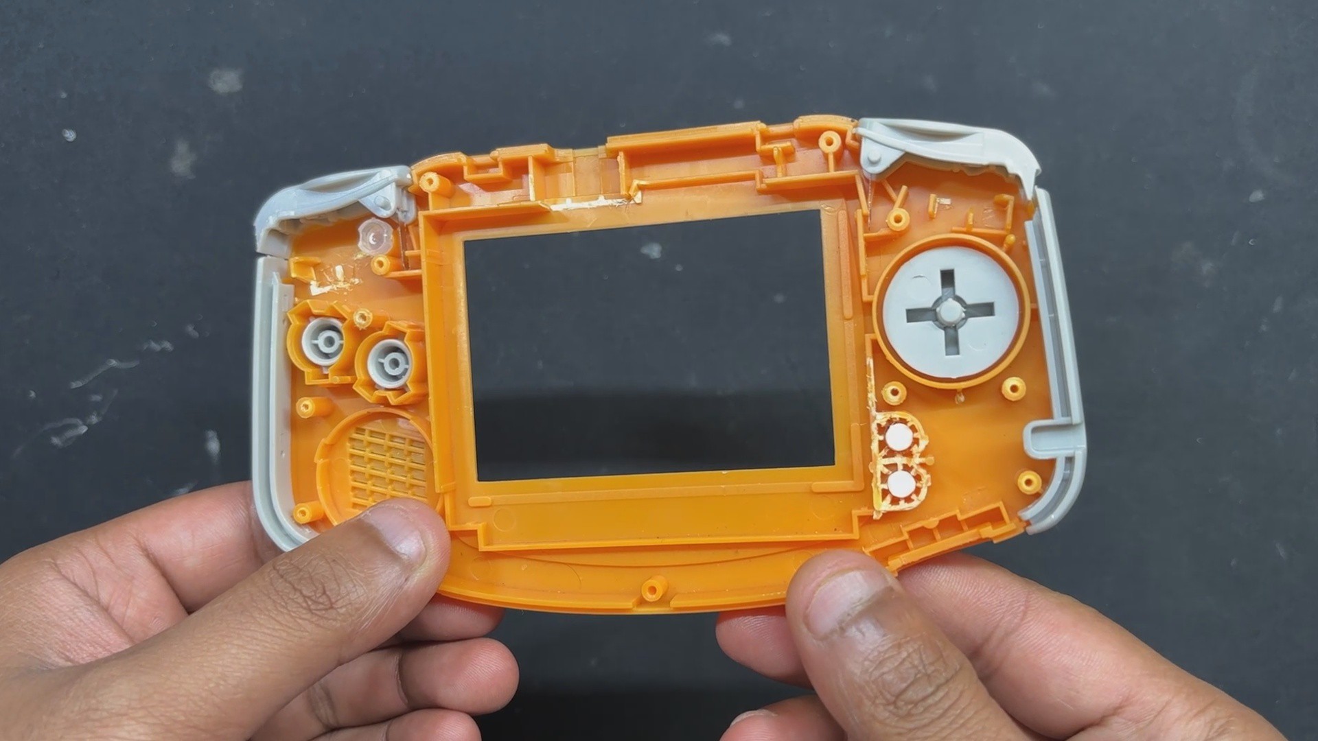
One of the most important parts of this project is the Original Nintendo Game Boy Advance replacement body kit, which I purchased from a retro game vendor that sells vintage consoles like the PS1, PS2, XBOX, and others at a local electronics market.
I saw this orange Game Boy advance shell while the seller was selling replacement body kits for handheld devices, and it made me think, "Why not build the entire Game Boy from scratch?" Since the body is brand new, all I had to do was develop the circuitry, which should be really, really simple.
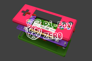
The D-pad, A, B, and trigger buttons are all included in this shell, along with the front and rear enclosure and a few more pieces on the left and right sides of the device.
It even features a Game Boy Advance logo and a front PC Cover, this PC cover part has an adhesive tape stick on the back, which allows us to take off the protective covering and attach it to the front body.
Shell Body Edit


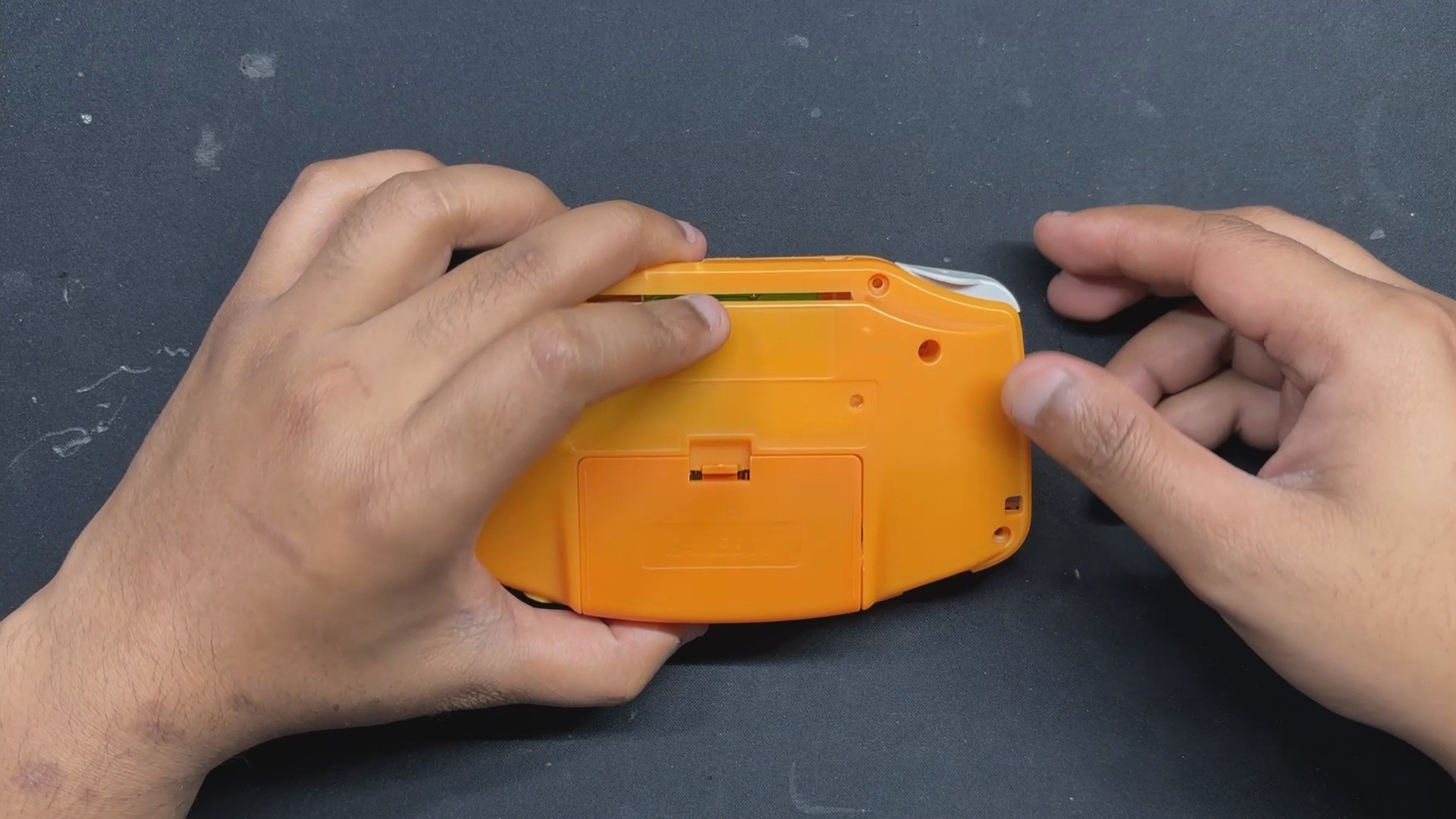
We can construct our PiBoy in this shell, but there is a minor glitch: the Game Boy Advance's PCB size. The existing PCB of the Game Boy is smaller than our PICO and other components. To create room for the new circuit, the Game Boy's battery compartment, which is located on the back end and a few pillars must be trimmed out.
- Using nipper pliers, we began the shell body edit process by removing the screw bosses on the left and right sides of the rear end.
- The AA cell holder is then fully removed; however, we must be careful not to remove the lock mechanism,...


 JohSchneider