 Arnov Sharma
-
1PCB Assembly Process
![]()
![]()
![]()
![]()
![]()
![]()
![]()
![]()
![]()
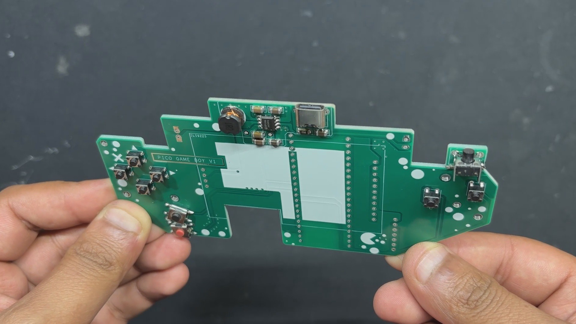
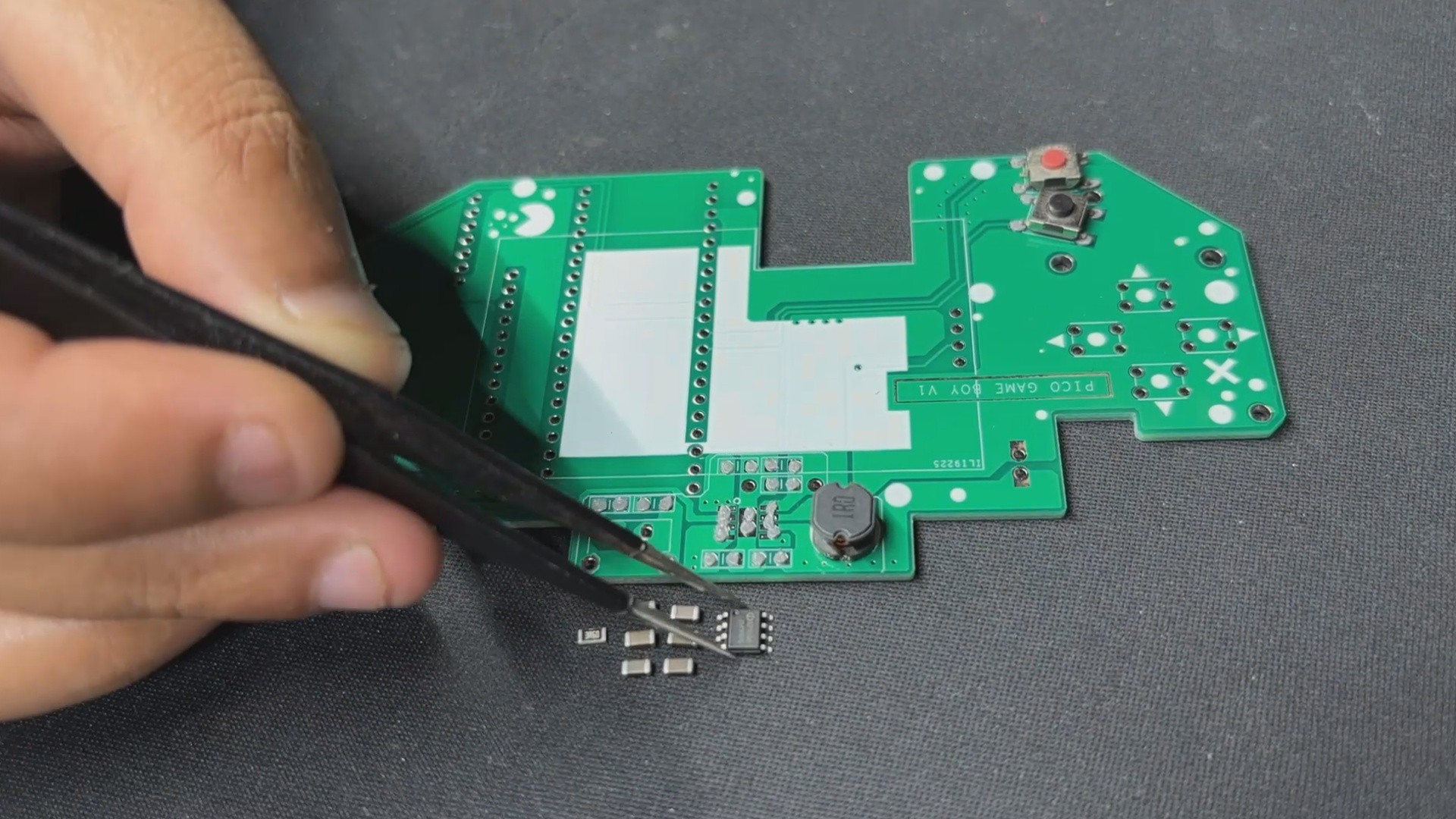
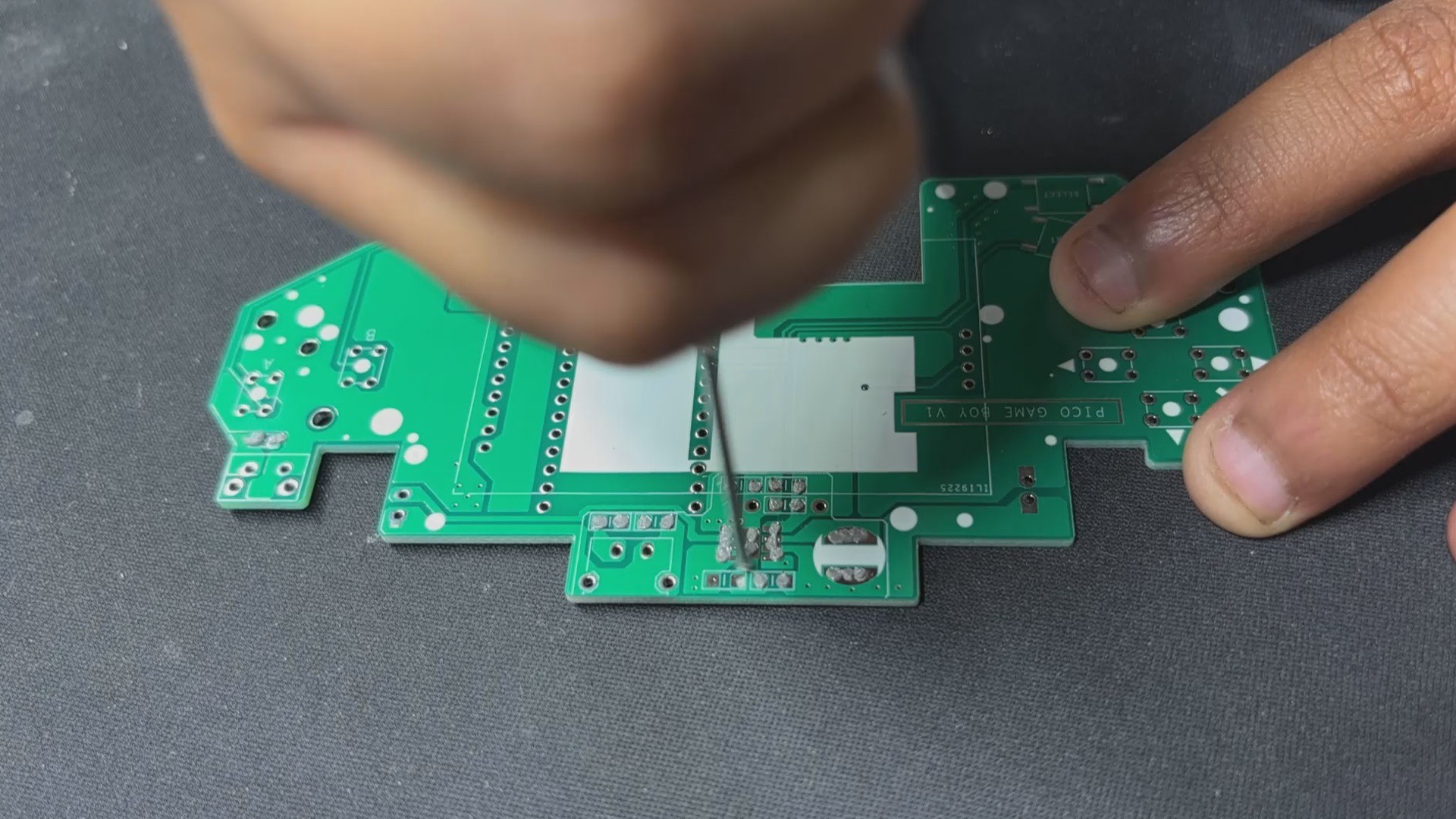
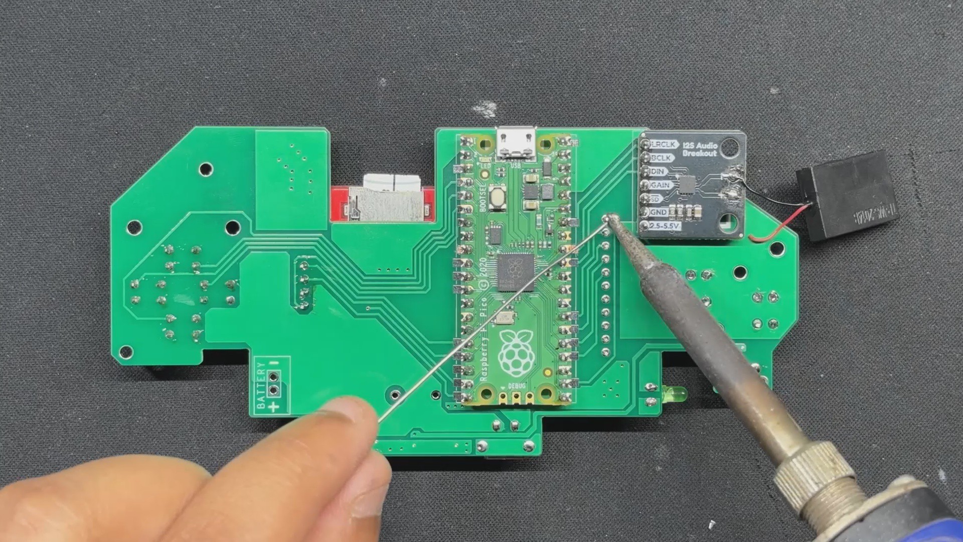
- The assembly begins with applying solder paste to each SMD pad using a dispensing syringe. For this build, we used 63/37 Sn/Pb solder paste, carefully placing it on every surface-mount pad.
- Next, each SMD component is positioned using ESD-safe tweezers, aligning them precisely over their respective pads. Once everything is in place, the board is transferred to a reflow hotplate, which heats the PCB from below until the solder paste melts and secures the components permanently.
- With the SMDs done, we move on to the through-hole components. First, the vertical push button is inserted, followed by the remaining push buttons and finally the USB Type-C port. The board is then flipped, and all THT pads are soldered from the underside to lock the components in place.
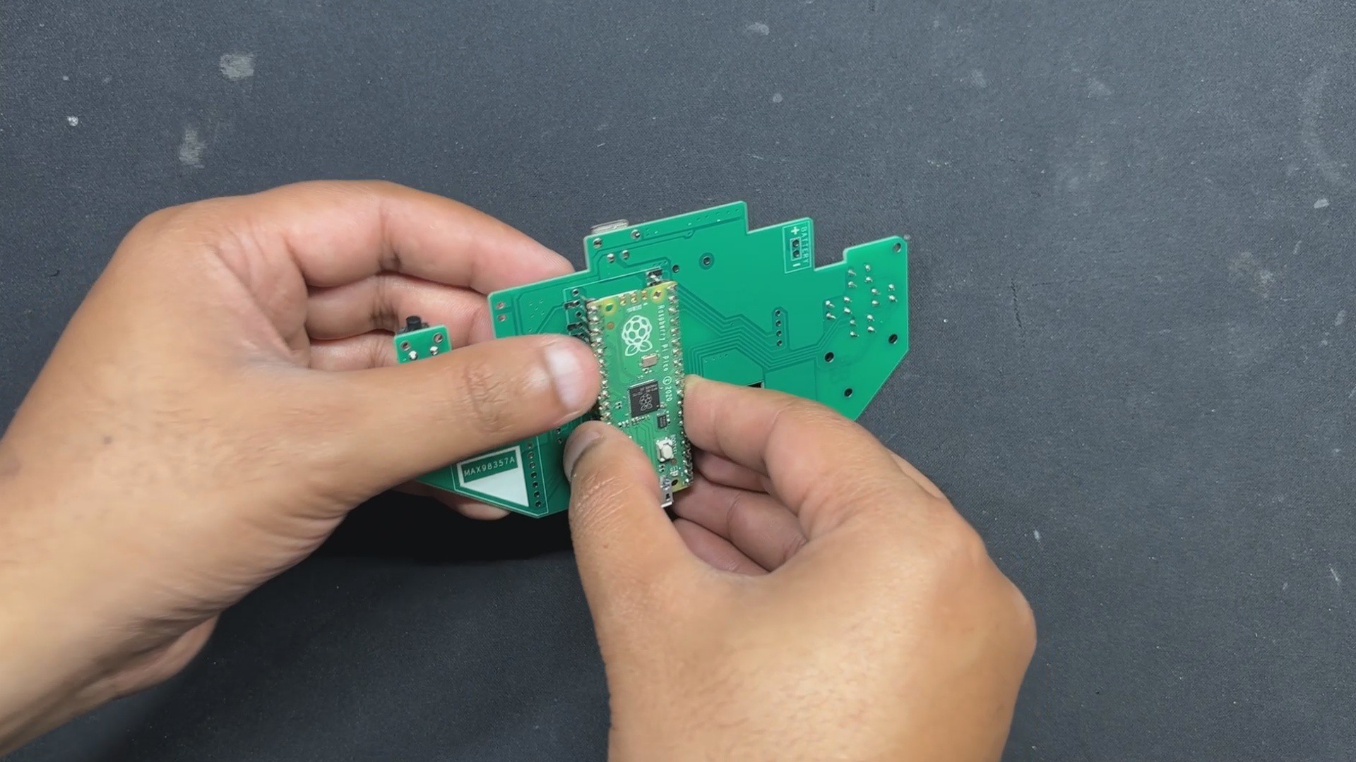
- The Raspberry Pi Pico is mounted next—positioned from the bottom side of the board and soldered from the top to ensure a solid connection. We then use a nipper to trim the excess header pin leads, keeping the profile slim and clean.
- After that, the MAX98357 audio module is placed on the bottom side and soldered from the top. Once secured, its leads are trimmed as well. A 3mm green LED is added from the top side, soldered from the bottom, and trimmed to match the low-profile design.
- Finally, the ILI9225 display is mounted from the top side and soldered from the bottom. To wrap things up, a small speaker is attached to the front of the PCB using double-sided tape.
With all components in place and soldered, the circuit assembly is complete.
-
2Power Source
![]()
![]()
For PiBoy Advance, we chose a 1000mAh 3.7V LiPo cell as the power source. Its compact size made it a perfect fit inside the Game Boy Advance shell. While we initially hoped to use a higher-capacity battery, space constraints made that tricky. Thankfully, it’s not a major issue—this device draws significantly less power than typical Raspberry Pi-based emulation setups. With the 1000 mAh cell, we’re getting a solid 2.5 to 3 hours of gameplay, which is honestly impressive. It even outperforms my ROG Ally, which barely manages an hour!
The battery assembly process was straightforward. We soldered the positive terminal of the LiPo to the Battery CON + pad on the PCB, and the negative terminal to the Battery CON – pad. To secure the cell to the back of the board, we used double-sided tape and press-fit it into place—keeping the setup clean, stable, and low-profile
-
3Shell Assembly Process
![]()
![]()
![]()
![]()
![]()
![]()
![]()
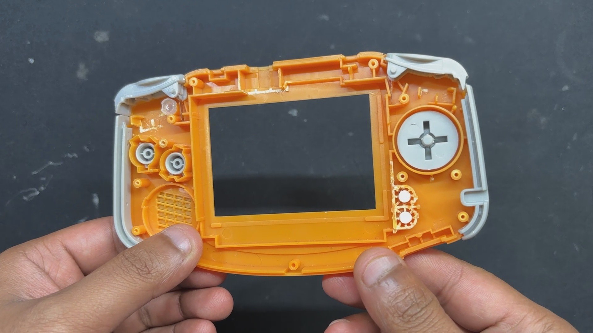
- The shell assembly process, which is the most crucial step in this build, starts with the installation of all the parts included in the GBA Kit to the front half of the body. These parts include the D Pad Button, A-B Buttons, Start-Select Buttons, LED Diffuser, Left Trigger-Right Trigger, and the Left and Right Accent Part.
- The Circuit is then positioned over the screw bosses, and the Circuit is fastened to the Front Body using four M2 screws.
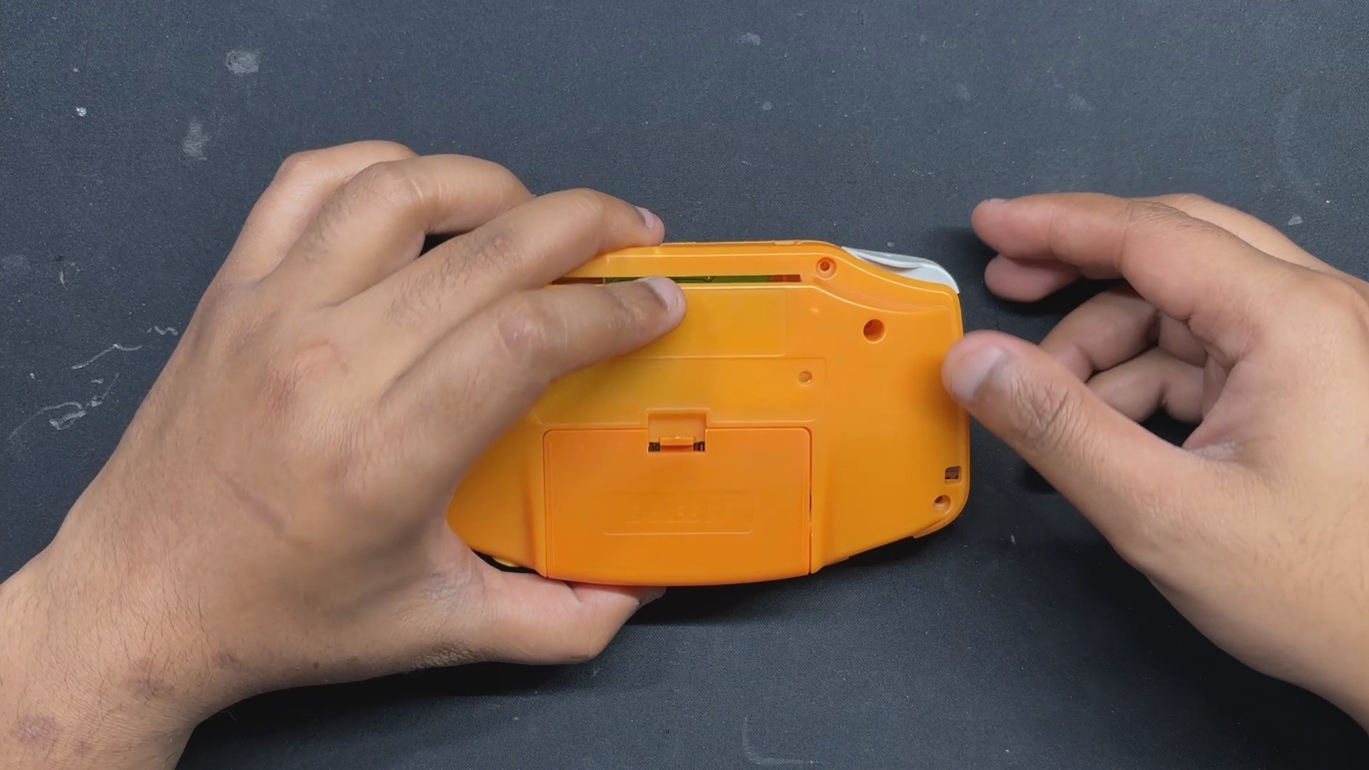
- After that, we position the rear half of the body and fasten the two halves together with six M2 screws, completing the assembly process.
The rear body features an AA cell holder lid. When opened, it provides easy access to the SD card slot and the Raspberry Pi Pico’s USB port, making debugging and updates straightforward.
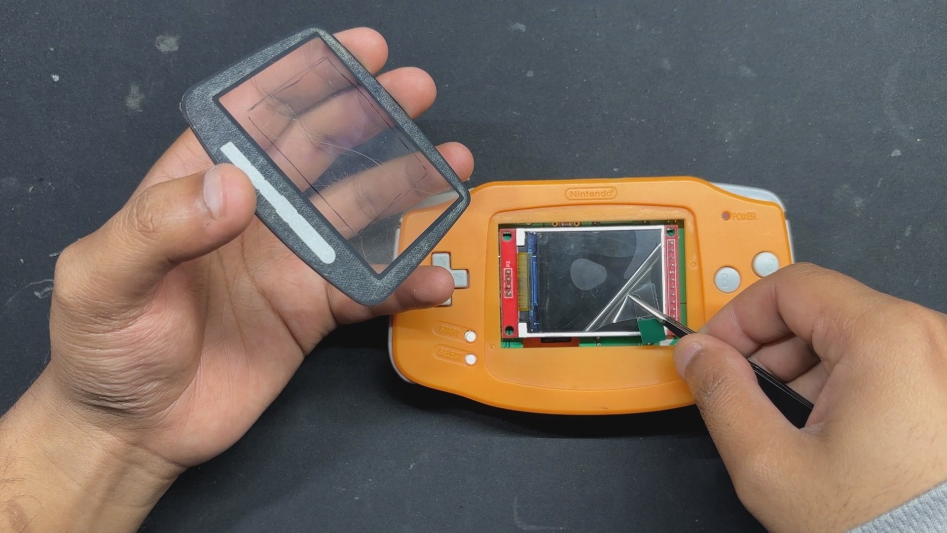
- We begin by peeling off the back protective film from the double-sided tape on the Front PC Cover provided in the kit.
- Next, we remove the protective film from the ILI9225 display.
- We then align the Front PC Cover with the Front Body and press firmly along the edges to secure it with the Front body.
- Finally, we peel off the outer protective layer from the PC Cover, revealing a clean, scratch-free surface.
With that, the assembly is complete.
-
4RESULTS
![]()
![]()
![]()
![]()
![]()
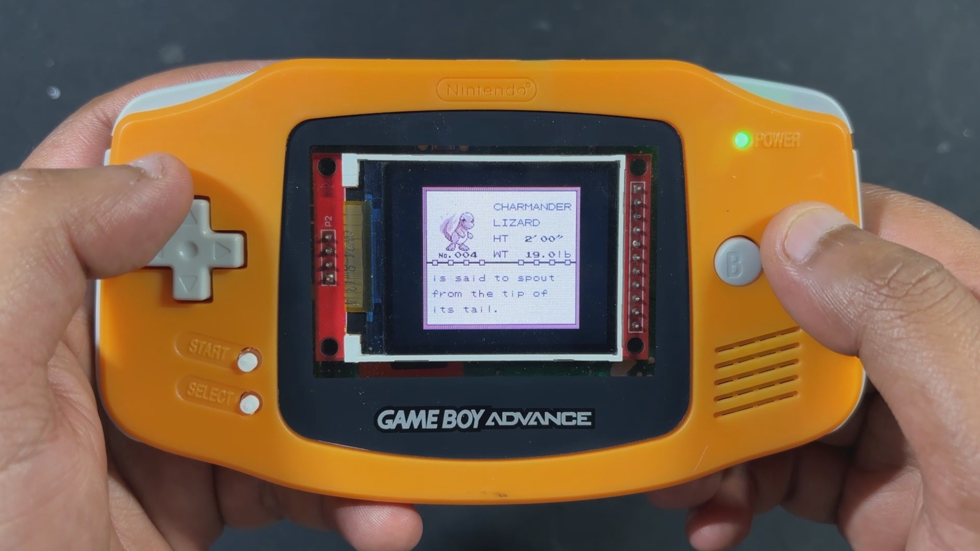
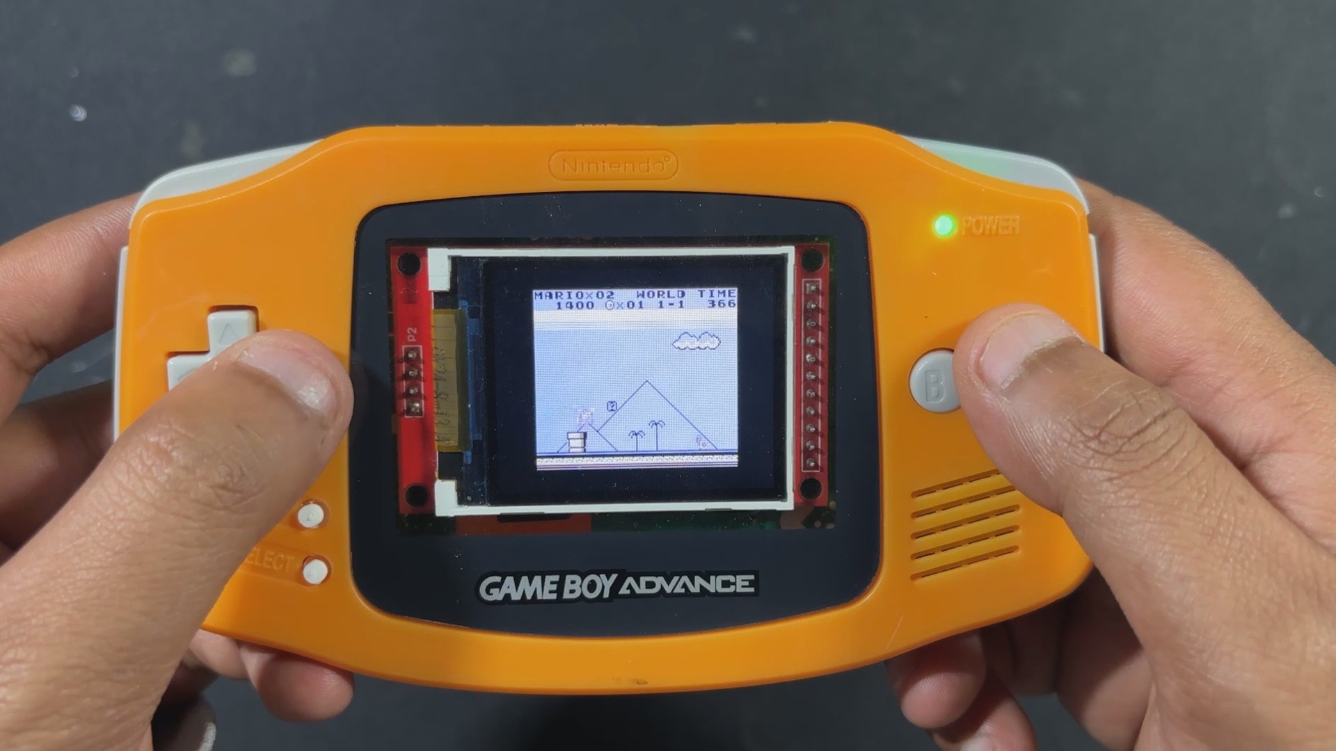
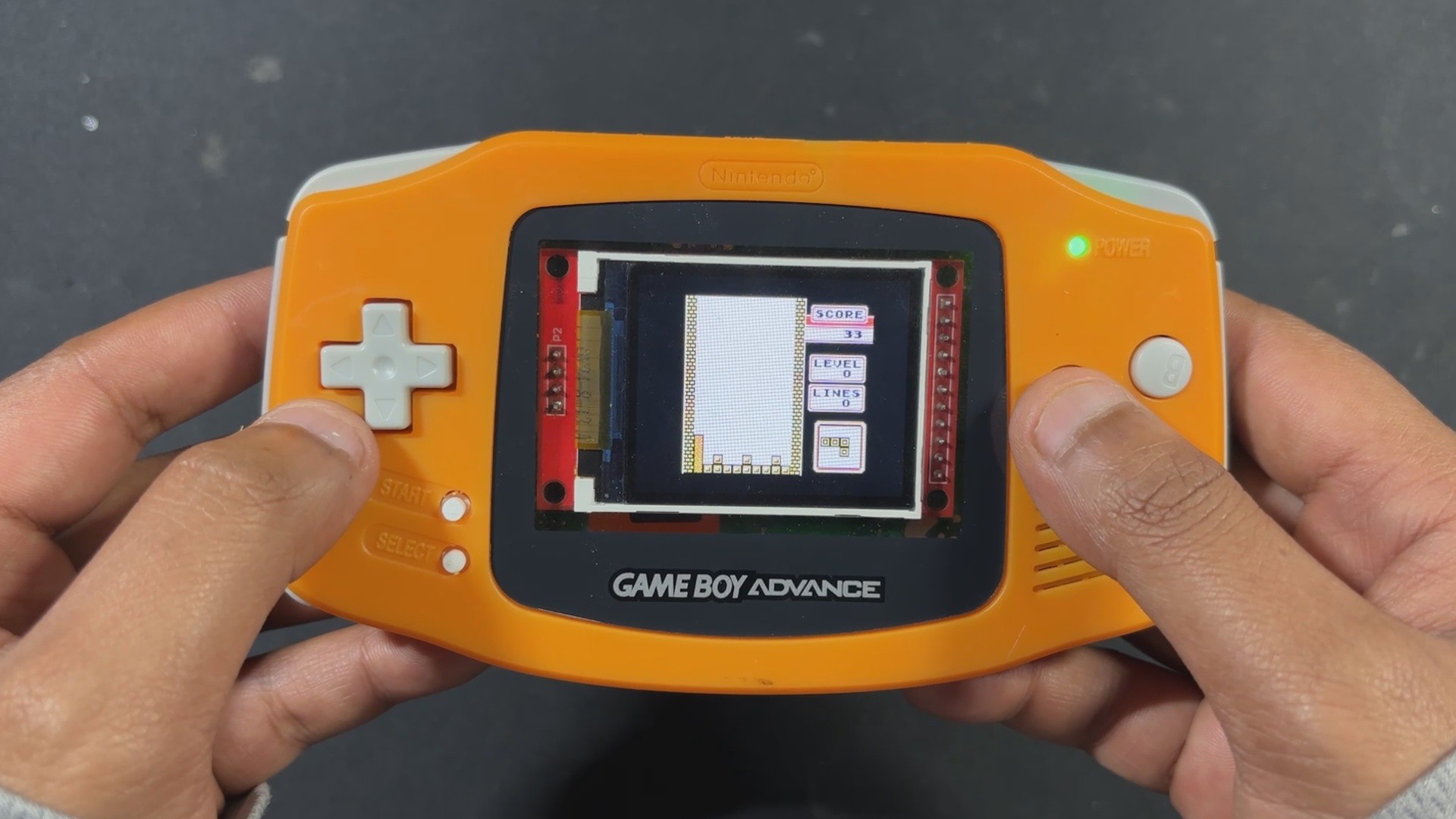
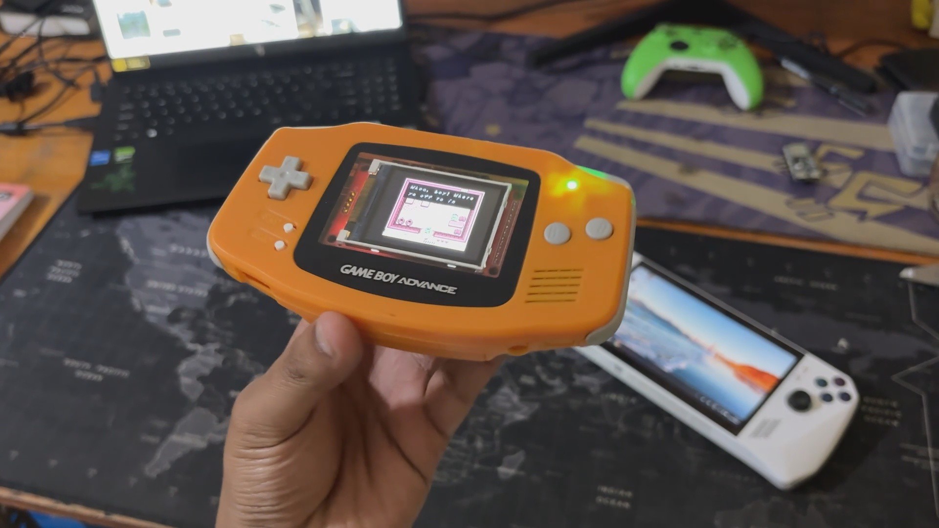
Here’s the end result of this small but seriously fun project: a handheld console that looks just like a Game Boy Advance, but inside, it’s running Game Boy games on a custom-built circuit powered by the Raspberry Pi Pico.
From the outside, it feels like a nostalgic throwback, but open it up and you’ll find a fully DIY setup—a custom PCB featuring the Pico, connected to an ILI9225 display, SD card slot, and audio module, all stitched together without relying on a full-sized Raspberry Pi board.
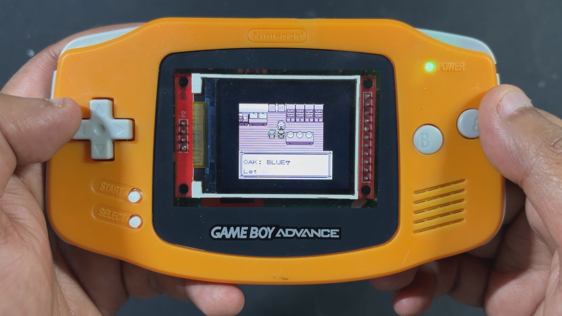
We ran a bunch of classics, from Tetris to Pokémon to Zelda, and the Pico handled every game flawlessly, without breaking a sweat.
Thanks to the onboard battery, we got a solid 2.5 to 3 hours of backup, which was perfect for outdoor use—we even took it trekking and played a few rounds when we reached our destination.
-
5CONCLUSION
![]()
![]()
Overall this project has been completed, and all the files related to this project are attached, which you can use freely for making your own PiBoy Advance!
There are a few things I’m already thinking about for the next version of PiBoy Advance. First up: battery life. Right now, it runs for about three hours, which honestly isn’t enough—this thing is addictive.
As a true retro gaming enthusiast, I want longer sessions without worrying about charging, so a higher-capacity battery is definitely on the list.
Next, the game code. The current Pico GB setup doesn’t support save files, which is a big limitation for story-driven games like Pokémon or Zelda. Save functionality is a must-have, and I’ll be working on adding that in future updates.
Then there’s sound. At the moment, the music plays at full volume with no way to adjust it. It works, but it’s not ideal. I’m planning to add a potentiometer wheel in the next version so players can control the volume more comfortably.
Finally, the shell itself. I originally thought reusing a Game Boy Advance body would be easier than designing one from scratch—and it was, at first. But I ended up having to trim and modify both halves quite a bit, which makes replication tricky and time-consuming. So for the next version, I’ll be designing a custom GBA-style enclosure with all the necessary edits built in. I plan to get it SLA 3D printed, which should give it a finish close to injection-molded plastic. Most likely, I’ll use a professional SLA printing service to get that clean, polished look.
For now, the build is complete, and all the related files are included in the attachments.
Special thanks to HQ NextPCB for providing components that I've used in this project; check them out for getting all sorts of PCB or PCBA-related services for less cost.
Thanks for reaching this far, and I will be back with a new project soon.
PiBoy Advance
PiBoy Advance is a modified GBA shell that is retrofitted with a custom PICO 1-based circuit.


Discussions
Become a Hackaday.io Member
Create an account to leave a comment. Already have an account? Log In.