 mattbart637
Motivation
This year I attended Open Sauce (2025) for the first time, and I spent a long time deciding what to build for it. I’d be flying there so whatever I built needed to be airport security friendly. I also didn’t want to be carrying around a heavy build for two days. A small wearable project sounded like a good idea and I had been kicking around the idea of making a custom watch for a while. This ended up being my first build outside the Arduino ecosystem and the smallest SMD soldering I’ve done to date. All things considered, I’m really pleased with how it turned out!
A huge inspiration was Joe Sullivan’s similar take on a PCB watch. I took a slightly different approach, simplifying the interface to a single tactile button. I preferred the cleaner look without the daughter board and (more importantly) I wasn’t up to dealing with the complexity of it.
Specs
| Dimensions | 29 mm diameter, 7 mm thick |
| Accuracy | 0.43 seconds/day, ~5 ppm |
| Current draw | 28.5 µA @ 3 V |
| Battery type | CR1220 |
| Runtime on 40mAh battery Draw | ~58 days (estimate) |
I only measured the accuracy and current draw on a single board so I don't know how repeatable they are. I'm pretty happy with the limited results I did get though.
Case Compatibility
Before I started designing anything, I needed to select a watch case and figure out how much room I had to work with. I eventually settled on cases designed for the Seiko NH35 movement and 29 mm dials. Seiko modding is a popular hobby and the NH35 a common movement, giving plenty of options in a variety of sizes on AliExpress (which came in handy when my wife said she wanted one too).
NH35 Spec: https://www.timemodule.com/uploads/attachments/download/Spec%20Sheet/NH35_SS.pdf
Component Selection
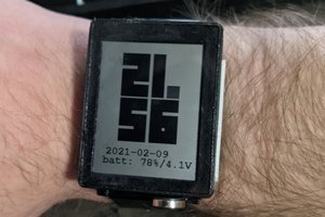
With an idea of the overall size, the next step was to figure out how to actually display the time. I used a 4-digit segmented LCD display complete with colon and three decimal points. It’s the right size and requires very little power to drive. I would’ve preferred more digits to also show the date but couldn’t find a suitable part.
I used a PIC16F1938 as it has a bunch of handy features for this application: built-in LCD driver, low-power Sleep mode, and a dedicated 32.768 kHz oscillator driver. It’s available in both DIP (for prototyping) and SSOP (for PCB) packages with readily available programmers. Microchip also has application notes for building clocks with their chips (AN649) and readily available development boards. Since I was new to the PIC ecosystem, the Curiosity Board DM164136 was great for quickly getting started.
I went with a 32.768 kHz quartz crystal oscillator to keep time, taking advantage of the PIC16's dedicated oscillator driver. It’s not temperature-compensated but accurate enough for me. I added a small tactile button for the user interface, a few passives, and filled the rest of the PCB with the largest battery I could fit: a 40 mAh CR1220.
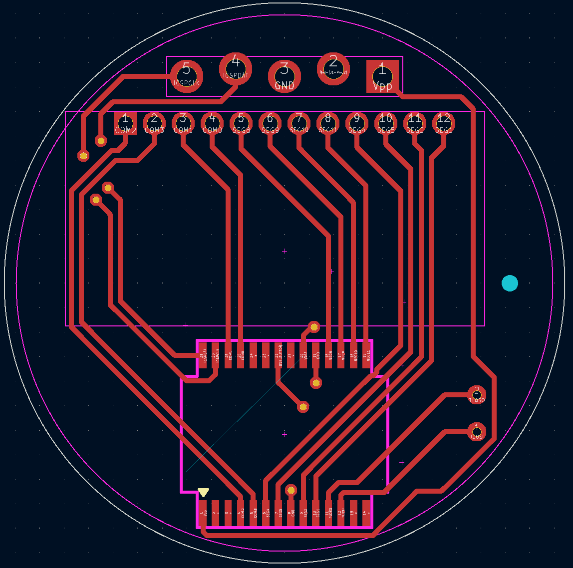
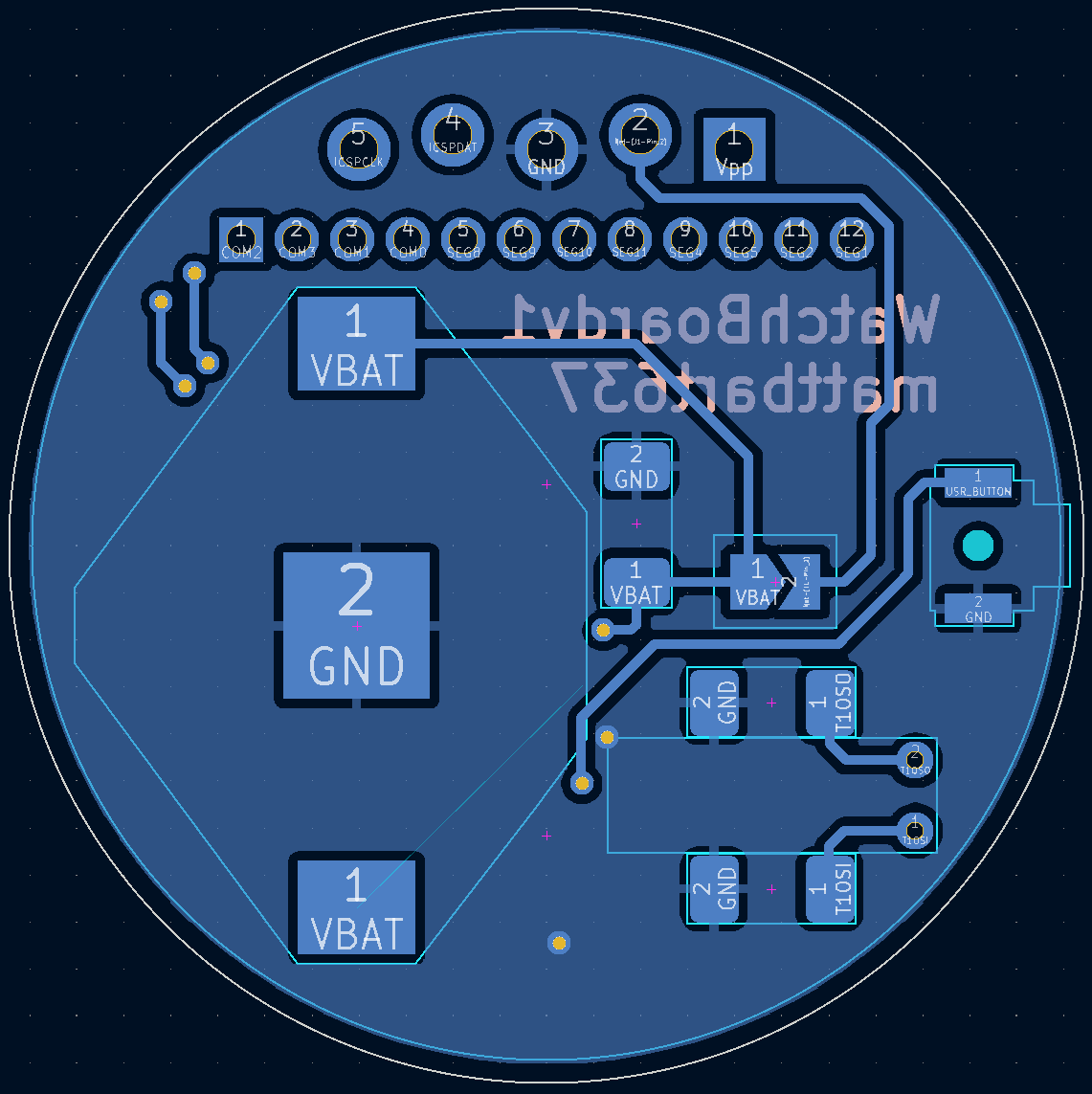
Board Layout
Since this is a watch, component placement was primarily driven by what I thought looked nice. That means only the PIC16 and LCD on the visible front side, and centered of course.
One tip I picked up from the Microchip dev board: the through holes for the programming header are staggered. It creates enough friction to hold a 0.1” pitch header in place for programming without having to add any extra features.
I designed some quick 3D-printed spacers to hold everything in the watch case at (mostly) the correct height. These were easily my least favorite part of the build. I hadn't built any anti-rotation features into the PCB, so the spacers have tiny features that register in the through holes for the programming header. I knew I'd have access to the DLP printer at my workplace to get myself out of trouble (and it did) but wish I had better planned this.
If I order more of these boards in the future I would include a keying notch to make the prints easier,...
Read more »
 Jeff Cooper
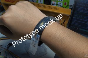
 TinLethax
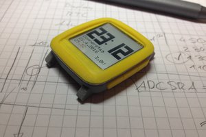
 Max.K
Max.K
it looks great but LF version of PIC would draw less current