Pierre-Loup M.
-
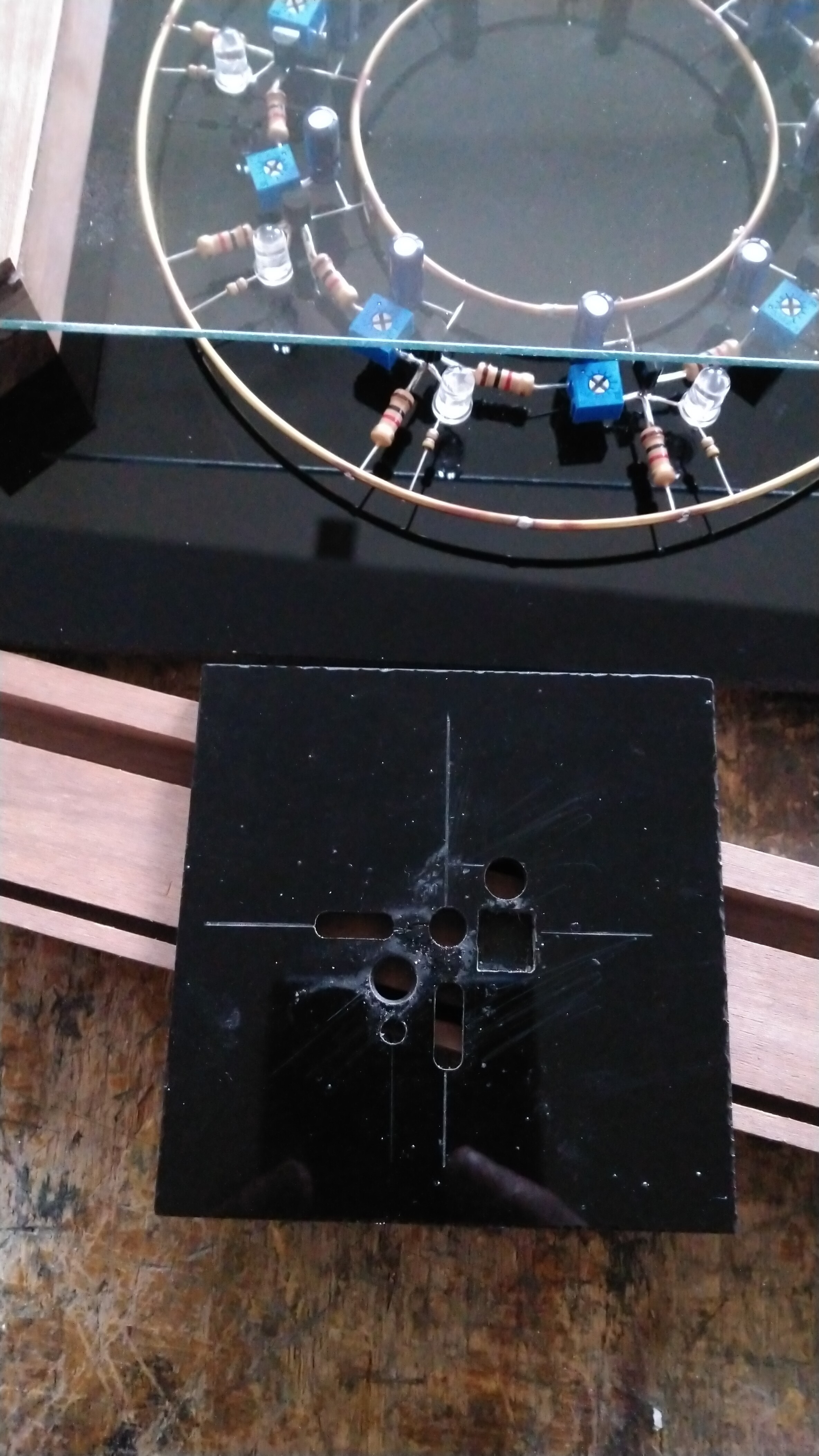
6 - Putting everything together.
07/30/2025 at 10:31 • 2 commentsThe circuit is assembled in freeform. A small template frame has been made to place each component and solder them together to form the nine gates with led and RC circuit.
![]()
Those gates have then been assembled on two rings made of 0.8mm brass wire. A simple paper template has been made to align each gate ate a 40° angle. The external ring brings VCC, the internal rings GND.
This assembly is mounted on a black 4mm acrylic plate, by three pegs on each ring, two of them being traversent to the back face.
On the back face are mounted a lipo battery, an Adafruit lipo charger with USB C, and a switch. The battery can then be charged, and the circuit powered from battery or AC adapter.
A wooden frame has been made, with the lower border mounted by two countersunk screws : it can be opened if needed, the circuit removed and cleaned or repared, the glass changed f broken, etc.
The circuit is 135mm in diameter, the frame is 180x180x37mm.
![]()
-
5 - Visual feedback
07/30/2025 at 09:52 • 0 commentsA ring oscillator is nice ; seeing that it functions is better. Leds on each stage give a nice visual feedback. They are mounted in parallel with the pull-up resistor.
![]()
They probably also account for the speed increase from the calculated RC values, as they are in the path of the capacitor charging.
-
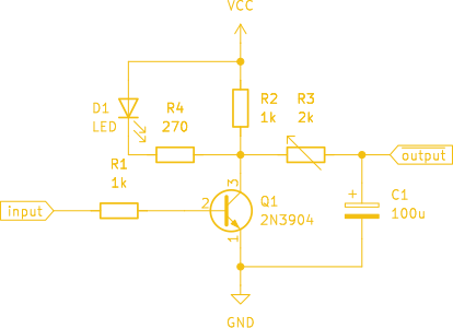
4 - Slowing down the propagation delay.
07/30/2025 at 09:45 • 0 commentsAs it is, the circuit oscillates far too fast for what we want. We thus need a way to slow it down. One way is to add an RC circuit on the output of each stage : capacitor take time to charge, and this time retards the propagation of the output state of a node to the following input.
See the updated schematic of the base node with such a RC circuit.
![]()
R3 and C1 are chosen accordingly to the timing required. The time constant of an RC circuit is given by the following formula :
with:
τ in seconds
R in ohms
C in faradFor nine nodes in the circuit, the individual time needed for one gate would be 1/9 = 0.111s. For a 1k resistor, it gives a 111uF capacitor value. I've settled for a 100uF cap, and a 2 kohm potentiometer to make room for fine adjustment. However, I failed to account for quite a few things :
capacitor charges through the pull-up resistor as well.
capacitor discharges through the input resistor.
transistor is saturated when Vbe is above 0.65V.
low level on output is 0.2V, not 0V.
Those forgettings causes the chosen values to be a bit faster than intended, but we are close enough to one second. -
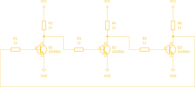
3 - Creating a ring oscillator from resistors and transistors.
07/30/2025 at 09:36 • 0 commentsYou may have seen it coming : just arrange any odd number of the previous circuit in chain linking inputs to outputs.
![]()
With three of them chained together, the circuit has a measured period of around 0.2us, which is a frequency of 5MHz.
-
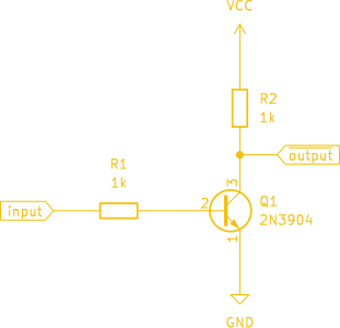
2 - Creating a NOT gate.
07/30/2025 at 09:31 • 0 commentsA NOT gate is quite easy to make with discrete components : a transistor and two resistors are enough. The transistor is used as a switch : it conduct current, or not.
- When a low level is applied on the transistor base (the input), it blocks current from flowing though it. The output is then pulled up to VCC by the R2 resistor.
- When a high level is applied on the transistor base, it conduct current, so its collector becomes "connected" to its emitter. The output is then almost GND (on this specific transistor, Vcesat is 0.2V, so that's the output low level.
![]()
-
1 - what's a ring oscillator anyway ?
07/30/2025 at 09:17 • 0 commentsA ring oscillator is a circuit that self oscillate, i.e. it oscillate by itself. It's composed of an odd number of NOT gates chained together in a ring arrangement, the last one being fed back to the first. The frequency of oscillation depends of the propagation delay of each gate. Being composed of an odd number of gates, the output of the chain will always be the logical NOT of the input.
This output, fed back to the input causes the chain to always invert its state.![]()
If you want to know more, please visit wikipedia (where I borrow this drawing) which explain it better than I do.
One hertz sculpture
Slowing down a ring oscillator enough to make it tick seconds