Németh József László
Project Details
This project is based on the ESP32 S3 microcontroller, integrated with an incremental rotary encoder for precise user input. The main objective of this build is to create a reliable and compact device capable of real-time signal processing and controlling outputs based on the encoder's position. The system uses PWM signals for efficient power management and feedback.
Key Features:
-
ESP32 S3 microcontroller: Acts as the heart of the project, handling both processing and communication tasks.
-
Rotary Encoder: Provides a user-friendly way to interact with the device, allowing users to change settings or navigate through options.
-
Custom Firmware: Developed using the Arduino IDE, the firmware is designed to handle inputs, control outputs, and manage device performance in real-time.
-
User Interface: A simple yet intuitive interface that provides clear feedback to the user through an OLED display and status indicators.
Components:
-
ESP32 S3 Development Board
-
Incremental Rotary Encoder (PEC11R-4115F-S0018)
-
100nF Ceramic Capacitor (for filtering and noise reduction)
-
10kΩ Resistor (for proper signal conditioning)
-
GX12 2P Connector (for power input)
-
Marquardt 1552.3102 Switch (for switching between different modes or configurations)
Challenges and Solutions:
-
Noise Reduction: The encoder's signal was prone to noise, so decoupling capacitors were added to filter high-frequency noise and ensure smooth input reading.
-
Power Management: Using a step-down DC-DC converter (3A adjustable) ensured efficient power regulation, providing stable voltage levels for the ESP32 and connected peripherals.
This project was built with modularity in mind, allowing easy upgrades and customizations. The 3D-printed housing ensures a compact and durable design, with easy access to components for future modifications or repairs.
Future Plans:
-
Adding support for multiple encoders for more complex control scenarios.
-
Improving the user interface to allow for more advanced settings and options.
-
Incorporating additional sensors for enhanced functionality.

 Daphne
 Louis H
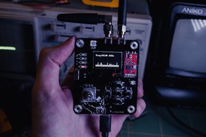
 CiferTech