 Nelson Phillips
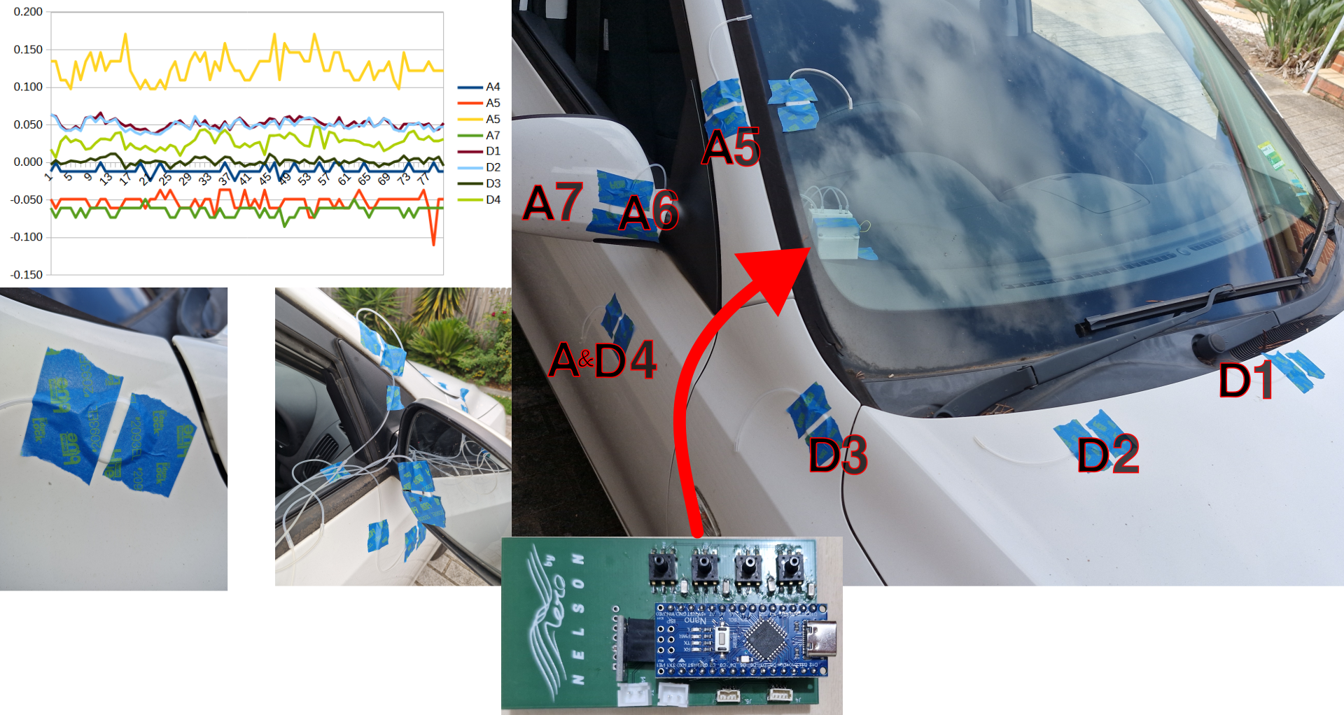
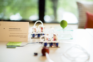
I usually make videos about vehicle aerodynamics with CFD. This simulation method is great for iterating through complex designs without physically making the devices tested. The problem is that the simulation is only as good as the model and then it still isn't in the real world with all the fine details. If a view of one my videos wanted to apply the findings to the real world there isn't a cheap accessible method to understand if it has work in a similar way. This pressure kit was intended to fill this need to measure the pressure field in the real world.
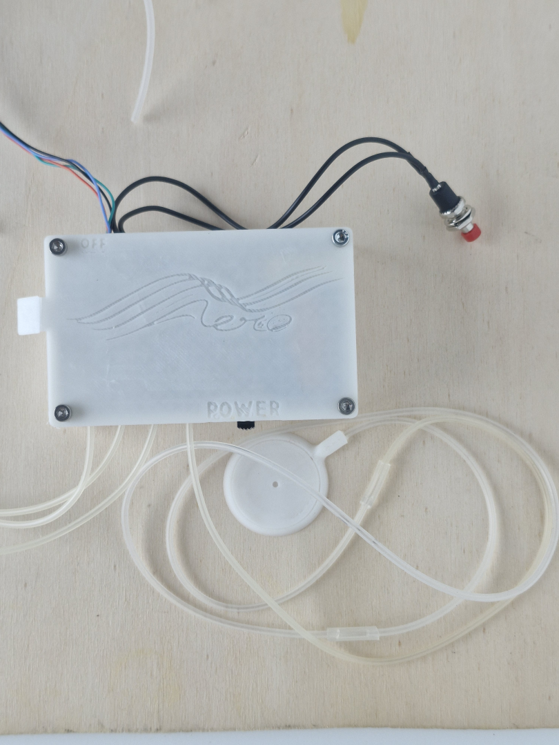
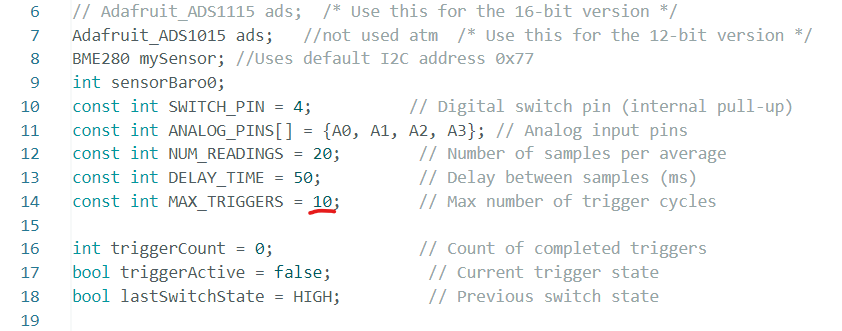
There are two versions of this kit, a basic one that has its design intension documented in the first video, and the second is a more advanced kit with extra memory and sensors. Both these kits production was documented in the second video.
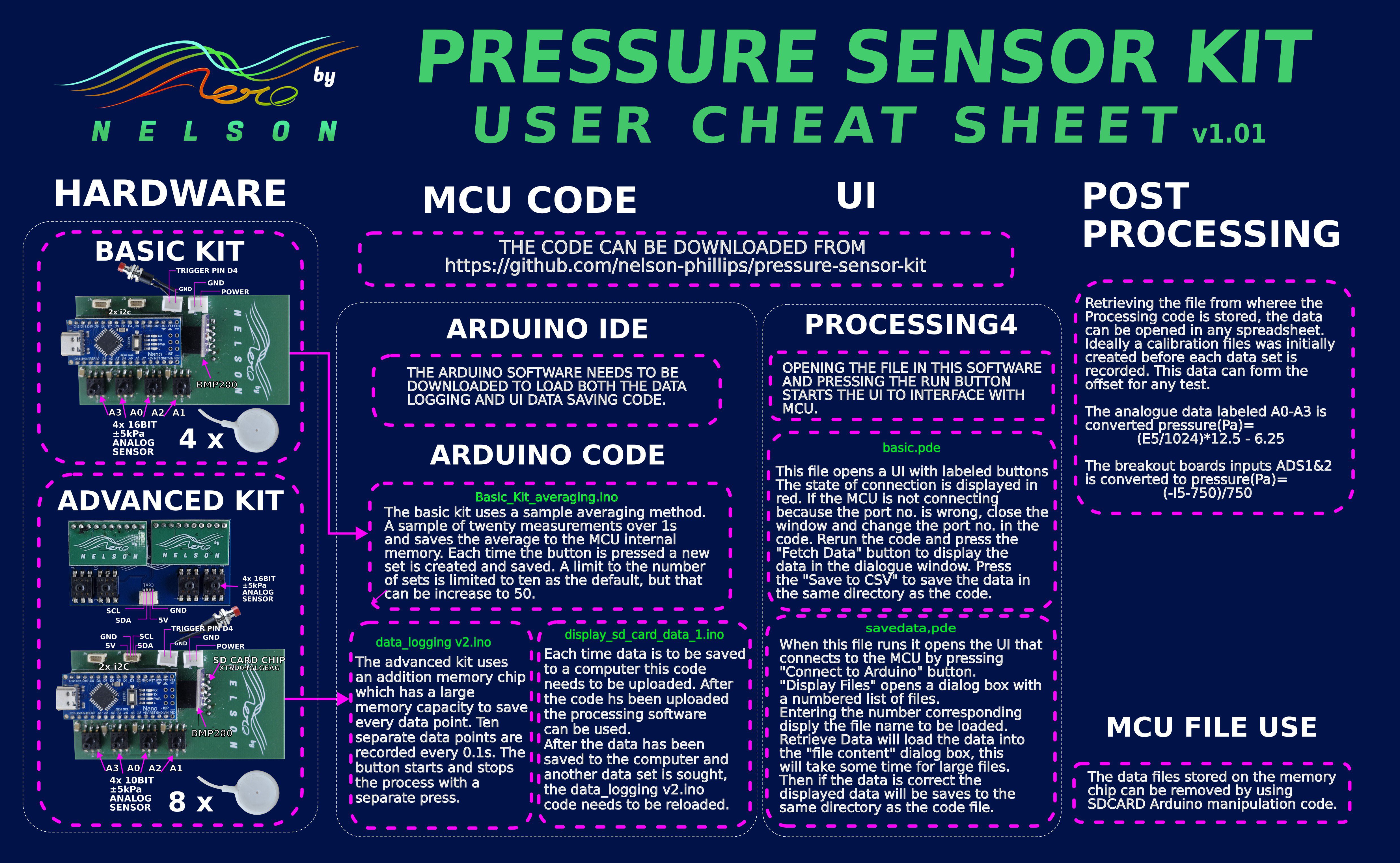
User manual as a cheat sheet. It can be downloaded below.
This first video covers the design of the kit and choice of electronic components.
The second video(part 2) covers the complete kit.


 Anool Mahidharia
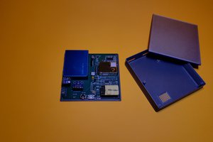
 Amitabh Shrivastava
 Simon Harvey