-
Lessons Learned
03/19/2017 at 09:13 • 0 comments- Inverse kinematics of delta robots are actually simpler than those of arms
- Accuracy depends heavily on the play in various parts
- Some cheap servos have a lot of play -- I think even SG90 servos would have been better
- Ball joints can have some play too -- make sure to get ones with smaller balls
- Unused PCBs make great building material, if you just remember to add holes in your designs
- Having a bag of nuts and bolts in your drawer is great
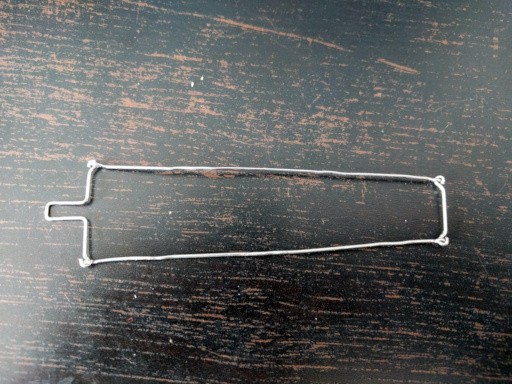
- Paperclips can be soldered to PCBs and make great loops for bolting things to
- When figuring out kinematics, don't draw your robot in the neutral position
-
Inverse Kinematics Redoux
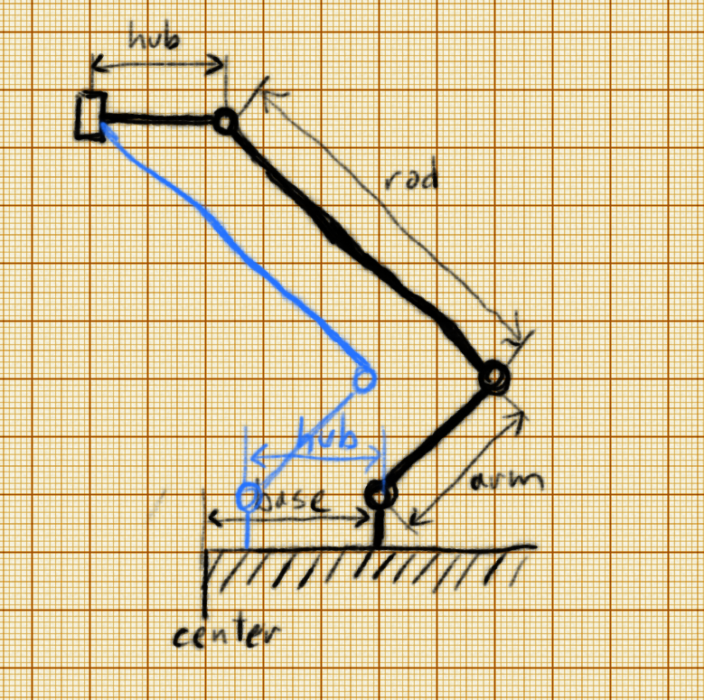
03/18/2017 at 21:59 • 0 commentsNow that I have it working, I should explain the inverse kinematics of this delta arm properly. First, let's just consider a single arm of the delta -- the other two are going to be pretty much identical:
![]()
The arm is attached to the servo at distance base from the center of the robot. It connects to the rod, which in turns connects to 1/3 of the hub. At the center of the hub is the actual tool that we want to move.
We can make a very large simplification in our model. If we skip the hub, and simply assume that the rod is connected to the tool directly, we can shift the whole robot by the length of the hub -- and all angles will remain the same. Since it's the angles that we want to compute, we can safely use this simplified model. So we will replace our base with tmp = base - hub. You can see the shifted robot in blue on the picture.
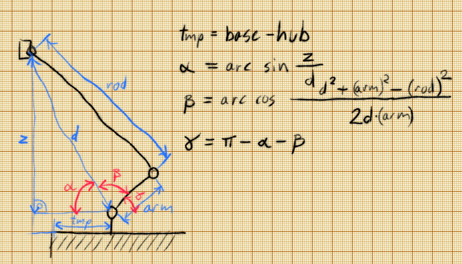
![]() We want to compute the angle γ, but to do that, we will compute angles α and β, and then γ = 180° - α - β. The angle β controls the length of this part of the robot, while the angle α controls its attitude -- so that it points towards our tool. All we know is the distance d of the tool to the servo, and the height z of the tool. We also know the dimensions of all the parts of our robot.
We want to compute the angle γ, but to do that, we will compute angles α and β, and then γ = 180° - α - β. The angle β controls the length of this part of the robot, while the angle α controls its attitude -- so that it points towards our tool. All we know is the distance d of the tool to the servo, and the height z of the tool. We also know the dimensions of all the parts of our robot.We can calculate angle α directly from the definition of the sine function: sin α = z / d. The triangle that β spans is not a right-angle triangle, so we can't do the same trick. But we know all the sides of that triangle, so we can use the law of cosines to calculate its angles.
![]()
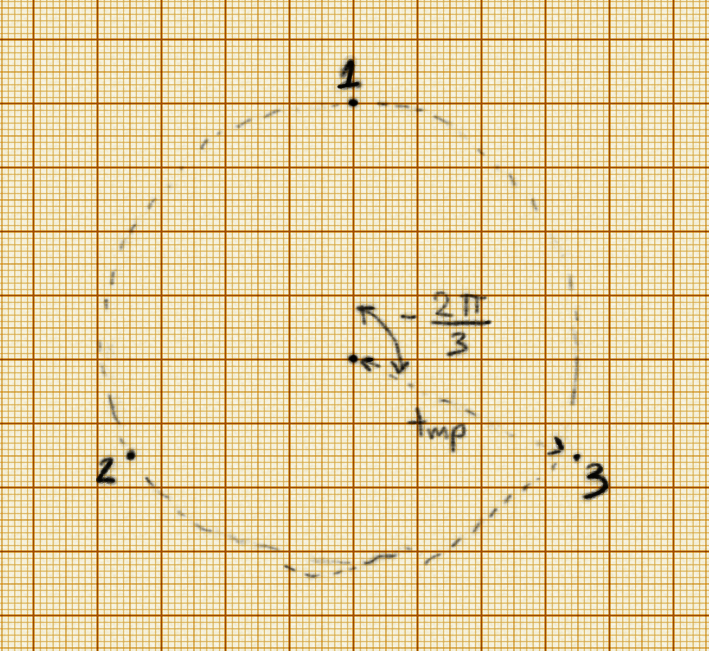
Now, all that is left for us is calculating the z and d for each of the 3 parts of the robot. Actually, z is the same as given in the (x, y, z) coordinates that specify the position of the tool. All we need then is d, which is the euclidean distance between the tool and the servos of each of the parts. The first part is easy: its x coordinate is 0 and its y coordinate is tmp. The other two points are rotated from that by 120° -- so their positions are (tmp * sin 120°, tmp * cos 120°) and (-tmp * sin 120°, tmp * cos 120°). The z of all three points is 0.
And that's it. That's all that is needed to control this robot.
-
Z is Required
03/18/2017 at 20:15 • 7 commentsAfter a whole day of debugging I finally found the error in mu routines that made the circle too small, and generally bad positions. Turns out that to compute the angle of the arm, you need more than just the distance to the target point -- because the arm+rod combo also need to be pointing towards that point. So you need to know the distance and the height.
I couldn't spot the mistake, because in all the pictures I drew, I drew the arm in approximately the same position, in which, by coincidence, the height was just right. But in the general case it won't work. So here are the corrected inverse kinematics routines:
    def arm_ik(self, distance, z):
        alpha = math.asin(z / distance)
        beta = math.acos(
            (distance ** 2 + self.ARM2ROD2) / (2 * self.ARM_LENGTH * distance)
        )
        return math.pi - alpha - beta

    def robot_ik(self, x, y, z):
        return tuple(math.sqrt(
            (self.BASE_X[arm] - x) ** 2 +
            (self.BASE_Y[arm] - y) ** 2 +
            z ** 2
        ) for arm in (0, 1, 2))

    def move_to(self, x, y, z):
        for arm, distance in enumerate(self.robot_ik(x, y, z)):
            self.move(arm, self.arm_ik(distance, z))
Oh, I also separated the ARM2ROD2 = ARM_LENGTH ** 2 - ROD_LENGTH ** 2 constant, so we don't have to recompute it each time. -
Code
03/18/2017 at 17:13 • 0 commentsI have the basic code for the inverse kinematics of the robot working:
import math
from machine import I2C, Pin
import servo


PI2 = math.pi / 2
PI3 = math.pi / 3


class Robot:
    ARM_LENGTH = 42
    ROD_LENGTH = 134
    HUB_LENGTH = 27
    BASE_LENGTH = 62

    BASE_X = (
        0,
        (BASE_LENGTH - HUB_LENGTH) * math.sin(2 * PI3),
        (BASE_LENGTH - HUB_LENGTH) * math.sin(4 * PI3),
    )
    BASE_Y = (
        BASE_LENGTH - HUB_LENGTH,
        (BASE_LENGTH - HUB_LENGTH) * math.cos(2 * PI3),
        (BASE_LENGTH - HUB_LENGTH) * math.cos(4 * PI3),
    )

    def __init__(self):
        self.i2c = I2C(-1, Pin(5), Pin(4))
        self.servos = servo.Servos(self.i2c, min_us=700, max_us=2400,
                                   degrees=180)
        self.trims = (0, -0.1, -0.2)

    def home(self):
        self.move(0, 0)
        self.move(1, 0)
        self.move(2, 0)

    def move(self, arm, radians):
        radians += self.trims[arm] + PI2
        self.servos.position(arm, radians=radians)

    def arm_ik(self, distance):
        alpha = math.acos(
            (self.BASE_LENGTH - self.HUB_LENGTH) /
            (distance)
        )
        beta = math.acos(
            (distance ** 2 + self.ARM_LENGTH ** 2 - self.ROD_LENGTH ** 2) /
            (2 * self.ARM_LENGTH * distance)
        )
        return math.pi - alpha - beta

    def robot_ik(self, x, y, z):
        return tuple(math.sqrt(
            (self.BASE_X[arm] - x) ** 2 +
            (self.BASE_Y[arm] - y) ** 2 +
            z ** 2
        ) for arm in (0, 1, 2))

    def move_to(self, x, y, z):
        for arm, distance in enumerate(self.robot_ik(x, y, z)):
            self.move(arm, self.arm_ik(distance))
As you can see, shifting the servo by the width of the hub greatly simplified the equations. I am pretty happy with how it works -- managed to draw a circle on a piece of paper, and the circle is actually round. One thing is strange, though -- the circle was supposed to have 5cm radius, but it's around 2cm instead... I might have an error there somewhere. I will keep experimenting with it. -
Inverse Kinematics
03/18/2017 at 02:56 • 4 commentsInverse kinematics for delta robots seem to have an opinion of being very complex and un-intuitive. I don't really understand why, because to me they seem to be simpler then for most other robot arm configurations. Perhaps I'm missing something.
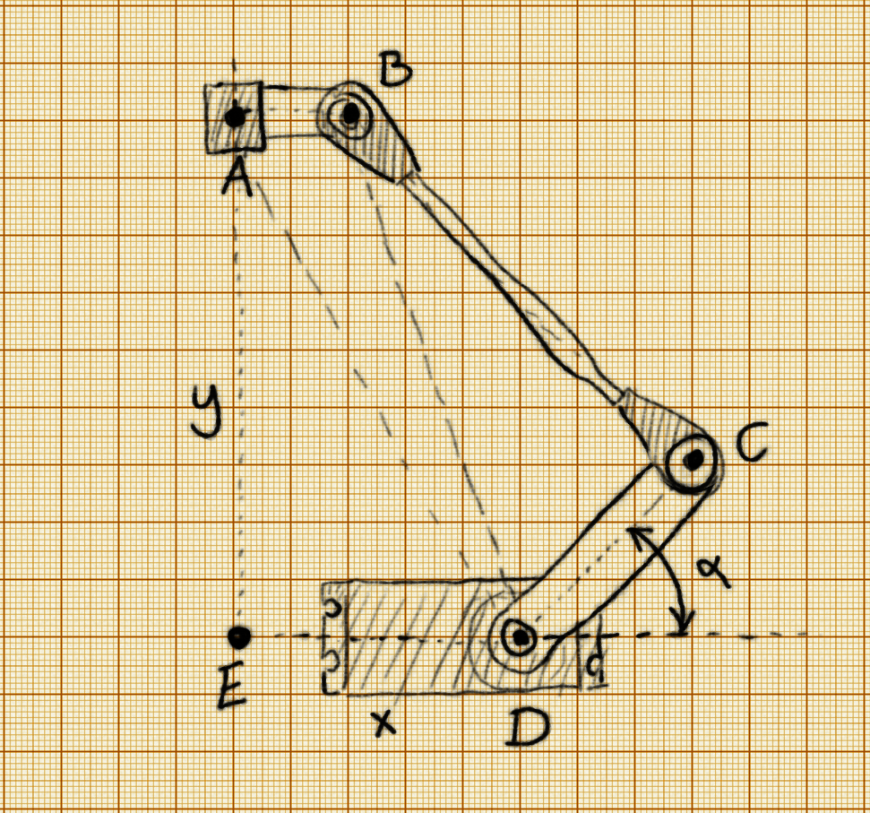
Let's split the problem in two parts. First, let's just look at 1/3 of the robot, a single "arm" of the delta:
![]()
We only have one degree of freedom here: the angle α. That's our output, what we need to calculate. And we only really have one input: the distance AD between the business end of the robot and the base of the servo. We also know all the mechanical dimensions of the robot: AB, BC, CD, DE. So how can we calculate α? From the law of cosines, of course! Given a triangle with dimensions a, b c, the law of cosines lets us calculate the angles of that triangle:
Where γ is the angle opposite c. Also, we will actually calculate 180°-α, which is a sum of three angles:
ADE, ADB and BDC. So we have:
And finally:
That's it. That's the position the servo needs to move to. All we need to know is the distance AD. How can we know that distance for each of the arms? That's very simple! It's just the distance between the point we want our robot to move to, (x, y, z), and the base of the given arm, (x₁, y₁, z₁), which we know (we can measure them or calculate from the distance ED and the angle of the given arm).
Applying all this math should let us move the robot to the coordinates we desire.
-
Paperclips
03/17/2017 at 16:54 • 0 commentsThe first approach wasn't very successful:
![]()
The joints would lock up and get into exactly the wrong positions. So I decide to try a little less gangsta approach and actually order some of those push rods for RC models -- ones that already have ball joint "snaps" on them. I made the order and forgot about the whole thing.
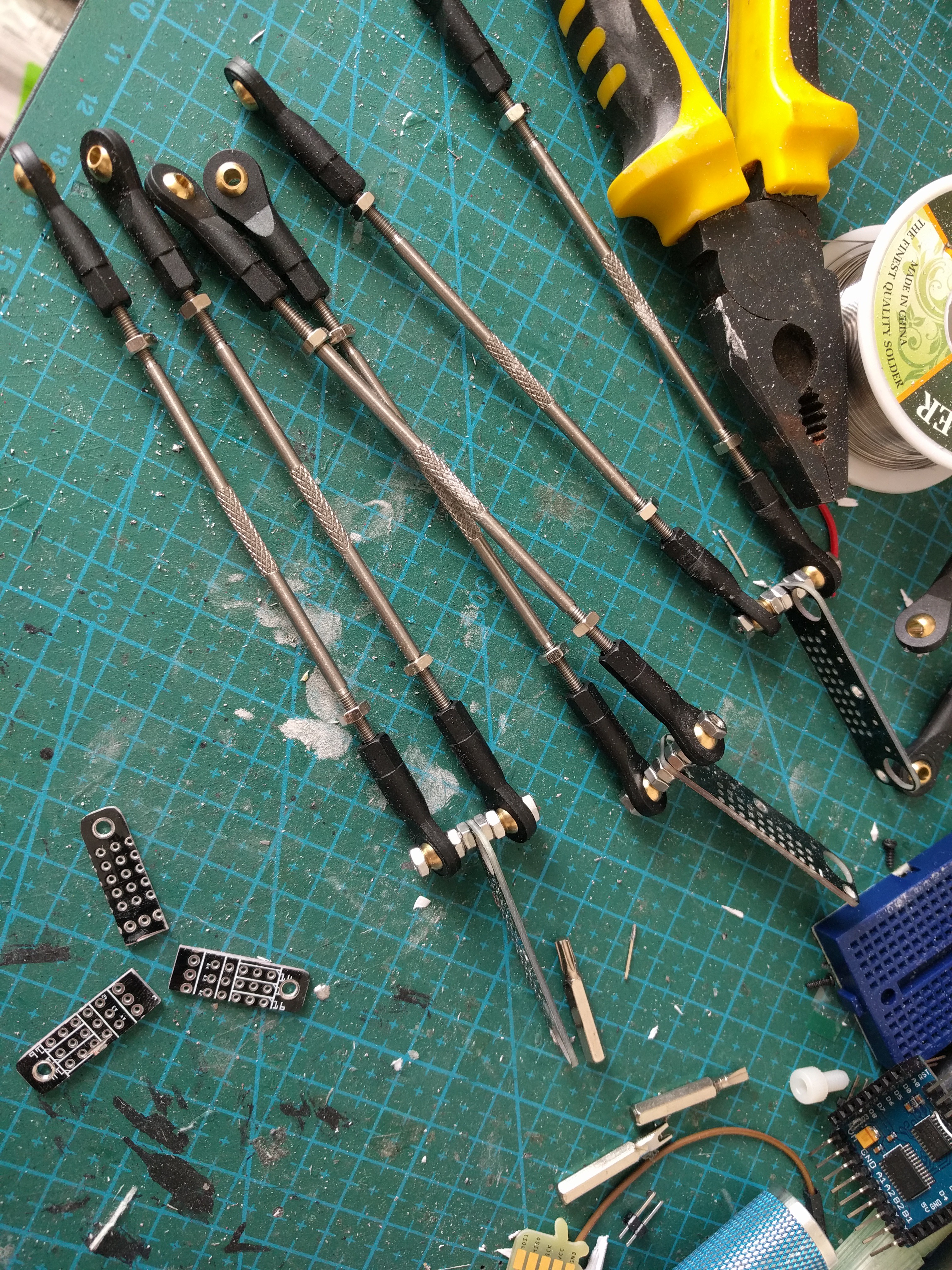
Today, they arrived, and I decided to continue the project. Initially I planned to make all the remaining levers out of paper clips, or to go posh and go to the nearby fablab and lasercut the parts. Then I looked at a stack of prototype PCBs for #Tote that I will never use (it's an older prototype) and noticed that they already have the holes for mounting the servo horns, so if I only cut them up a little...
![]()
This appears to be working quite well. I had to enlarge the screw holes a little, but otherwise they seem just perfect. Next, I had to make the center hub somehow. I decided to use the leftover pieces of the PCBs I have just cut up, and simply solder them together. Then, I realized I will probably want to have a hole in the middle, to install a pen or something, so instead of soldering them together directly I used some paperclips.
![]()
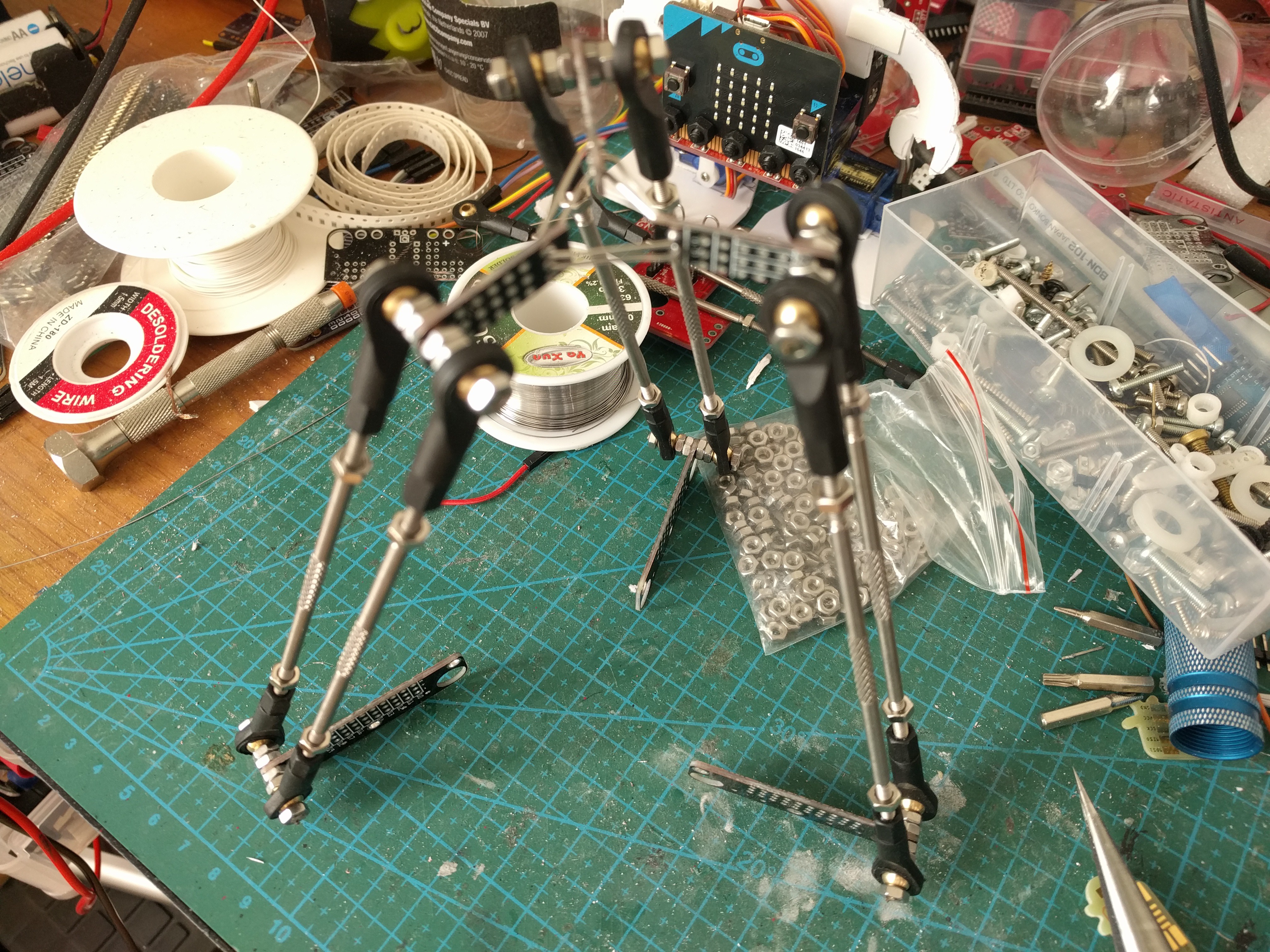
Then I just bolted the remaining PCBs together to create the base, and used two-sided tape to attach the servos to that. The resulting construction looks quite pleasing to the eye, in my opinion, and is reasonably rigid. Of course it's not perfect: both the ball joints and the servos have some play in them, which translates to the center hub being a bit wobbly -- so I probably won't have millimeter precision on this. But my main interest is in working out the inverse kinematics of this thing, so this is good enough.
 deʃhipu