Close
0%
0%

Yet another ultra low power LED

<1.5µA with consistent operation down to 1.81V

Similar projects worth following
Refining Christoph Tack's ultra low power LED design which is in turn based on Ted Yapo's TritiLED.

The ultra low power LED project by Christoph Tack improved upon Ted Yapo's TritiLED with the following banner spec:

1.36µA on a 3V power supply (1 LED, 3µs pulse width, 64Hz repetition rate).

I don't think that I can improve on these raw numbers much, but there are some details that can be improved:

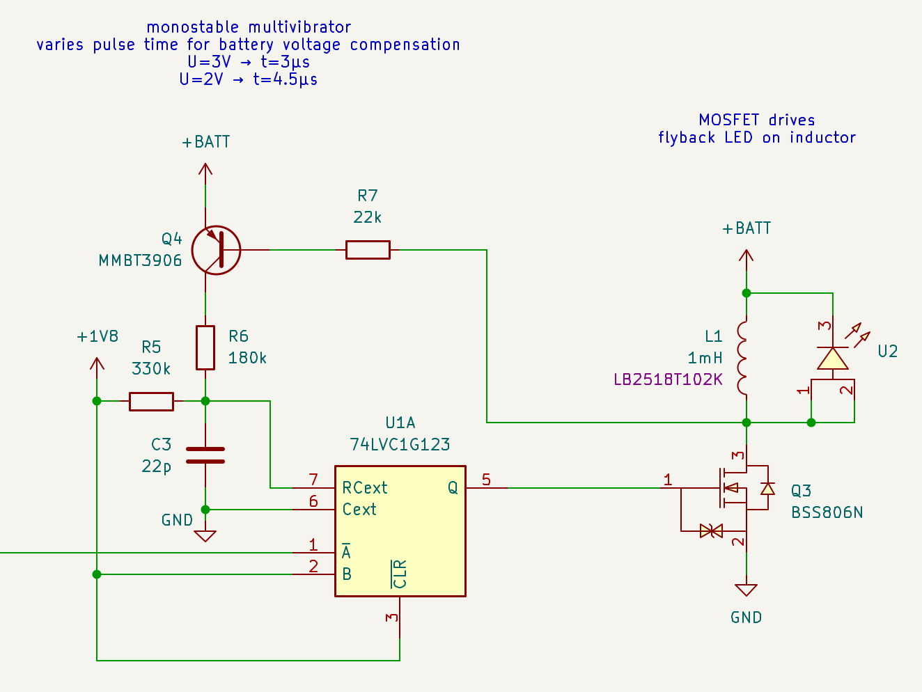
  • instead of an exotic RTC chip which is really overkill, build an ultra-low power oscillator out of jelly-bean transistors and some passives - by Dave Johnson at DiscoverCircuits.com
  • increase the pulse length as the battery voltage drops to maintain LED current.
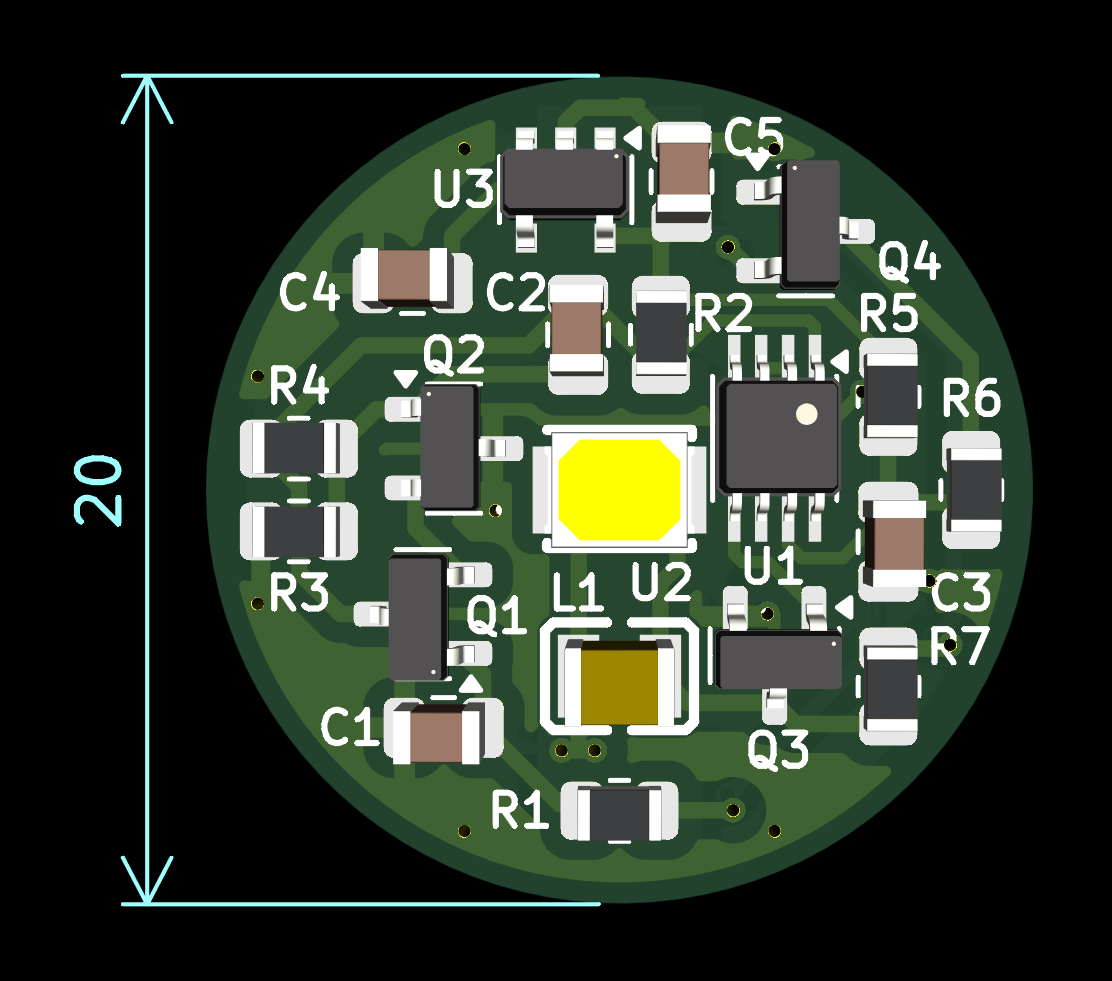
  • use a smaller inductor - a huge 12mm×12mm power inductor really isn't necessary

schematic.pdf

Adobe Portable Document Format - 37.66 kB - 09/01/2025 at 17:58

Preview

  • Coin-shaped PCB

    Stephan Walter09/01/2025 at 17:53 0 comments

    Apart from building the circuit on a breadboard, I have neglected the physical form factor so far.

    I now whipped up a circular PCB with a diameter of 20mm. It uses a CR1220 lithium cell which should be not much harder to obtain than a CR2032.

    KiCad files and production data are on Github.

    If you want to build this, beware that I haven't tried the particular MOSFET and inductor in the BOM. The LED may also not be the absolute best choice, but it's what was in stock at LCSC.

    This could definitely be made smaller, if one wanted:

    • use smaller passives, 0805 is what I have as an E6 kit and it's easy to solder by hand.
    • use a dual BJT transistor package (MMDT3946) for Q1/Q2, but then Q4 is the odd one out.
    • use a smaller package for the monostable. Nexperia has a SOT1116 which is 1.2 mm x 1 mm with 0.3mm pitch.
    • even smaller, even less popular battery size.

    But at this point I don't really have a concrete need for a particular form factor, so I haven't ordered PCBs yet.

  • Monostable multivibrator

    Stephan Walter08/20/2025 at 07:42 0 comments

    The oscillator output idles near the upper supply rail and produces low-going pulses.

    The pulse duration can be influenced somewhat by the choice of passives, but such fiddling also influences the oscillation frequency. It's best to separate the oscillation and pulse generation.

    As in the previous work by others, the 74LVC1G123 by TI or Nexperia is chosen here. The Nexperia datasheet includes a logic diagram.

    Another possibility to explore would be using two NAND gates - 74AUP2G00 should be suitable but I haven't looked into power consumption.

    The pulse length is calculated from the desired LED current and the inductance value:

    I'm sticking to the same values as Christoph: L=1mH, IRMS=5mA, Ipeak=9mA → ∆t=3µs.

    A low capacitance value for Cext (C3) reduces the amount of charge that gets "thrown away" for each pulse. As expected, there is a resistor R5 through which the capacitor is charged to Vcc.

    As the battery voltage drops, the pulse duration needs to be increased to maintain the same LED current. This is achieved using Q4 and R6. During the pulse, the PNP transistor switches the resistor to charge the capacitor quicker to the higher battery voltage. (A p-channel MOSFET might work as well, but the 3906 is already used for the oscillator).

    R6 has to be switched to avoid continuous current flow in the idle state, via R5 and through the body diodes of the 123's MOSFETs at the RCext pin.


  • Voltage regulator

    Stephan Walter08/19/2025 at 21:44 0 comments

    The oscillator circuit - using discrete components - is sensitive to changes in the supply voltage. Ideally we want to use a lithium battery for a large part of its discharge behavior. Capacity is typically given for a discharge down to 2V (e.g. 235mAh for a CR2032).

    To maintain a constant oscillation frequency, let's use a low-dropout regulator with an ultra low quiescent current. Texas Instrument's TPS7A02 seems unbeatable in that regard: 25nA.

    An output voltage of 1.8V was chosen, as this is a common voltage for low-power digital circuits, and supported by low-power logic families such as AUP or LVC.

  • Oscillator

    Stephan Walter08/19/2025 at 19:38 0 comments

    LEDs are most efficient at a current and light intensity that is much higher than what we want, so pulsing the LED is the solution. The frequency should be high enough to not be perceived as flickering (> 50Hz)

    Ted's TritiLED project used a PIC microcontroller for this. Christoph's ultra low power LED uses an RTC module that combines crystal and RTC IC (the Micro-Crystal RV-3028-C7).

    Both these are really overkill. They require loading either program code (for the PIC) or configuration values (for the RTC) into the respective flash memory or EEPROM. And while 1ppm accuracy in the RTC is nice, it's really not needed.

    I say let's go back to the roots - two transistors are really all that's needed for an oscillator.

    Dave Johnson at DiscoverCircuit.com proposes a circuit with NPN and PNP transistors connected a** to a** ... I mean emitter-to-emitter.

    The 3nA variant uses 1Gohm resistors which are not something everyone has in their parts bin. Also a typical multimeter can't measure that, so troubleshooting is more difficult. The 30nA/100Mohm variant is more reasonable in that regard.

    The original circuit targets a 1Hz rate, for a faster oscillation we decrease the capacitance values.

    Replacing the 4.7Mohm resistor connecting Vcc to the output with a much lower 680kohm value means that in the idle state, the output level is much closer to the positive supply rail - much better for the next CMOS stage.

View all 4 project logs

Enjoy this project?

Share

Discussions

Christoph Tack wrote 08/20/2025 at 14:39 point

Very good!  I simulated your oscillator in LTSpice and got about 91nA(rms), 52nA(average).  

I have my doubt about the 100M resistors.  What about leakage, PCB-dirt etc?

  Are you sure? yes | no

Stephan Walter wrote 08/21/2025 at 08:41 point

You are right that with such high values, those things can become an issue. I'm more worried about tolerances and differences in stray capacitance from my current breadboard setup to a PCB later. Might have to adjust some values.

  Are you sure? yes | no

Similar Projects

Does this project spark your interest?

Become a member to follow this project and never miss any updates