Wassim
-
Happy shellies in a local network
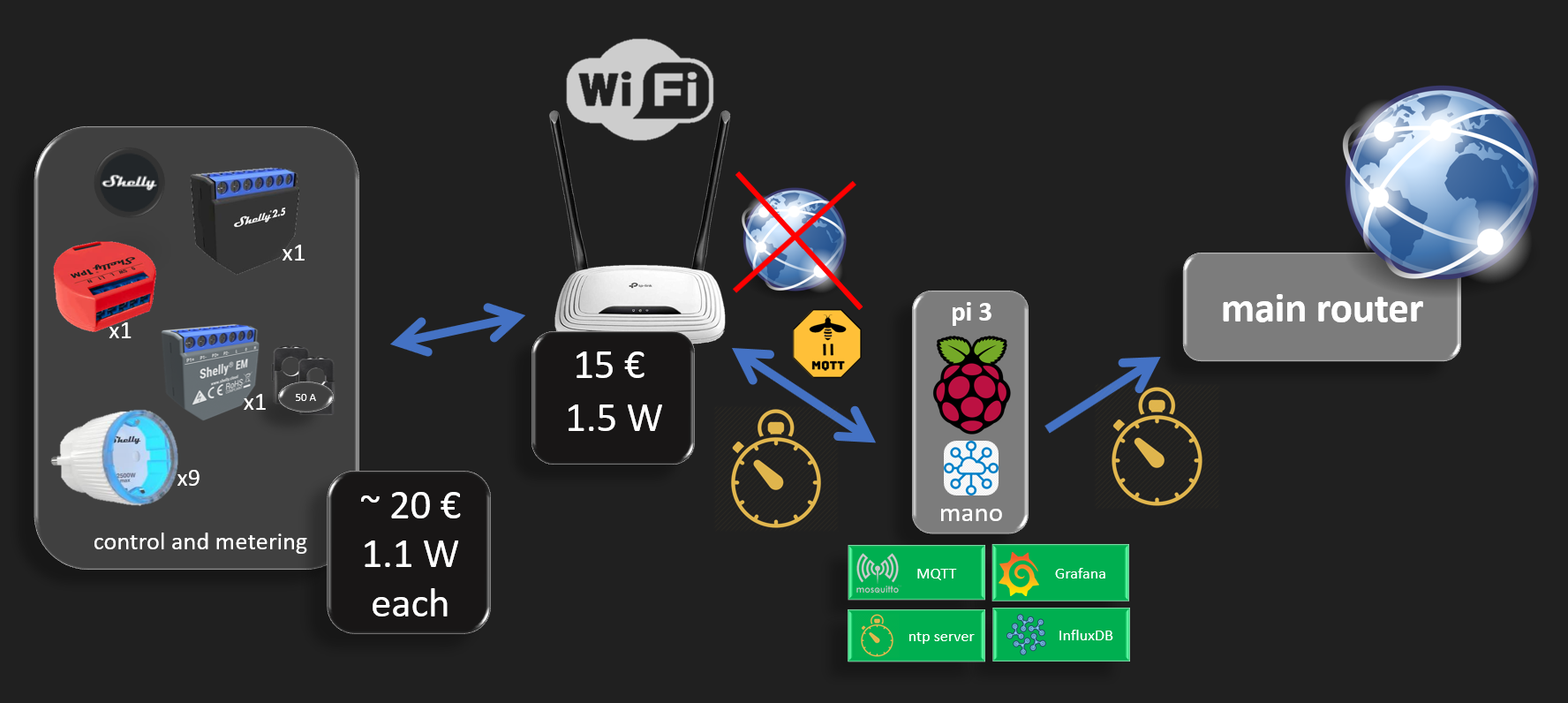
02/23/2020 at 15:36 • 1 commentThe diagram above shows how to achieve an isolated IoT environment that has no internet access and devices are running in a local network.
An additional security measure is to isolate IoT devices in their own local wifi network with their dedicated router. This way, even if any IoT device gets hacked, it cannot access the rest of your main router network where you might have open drive shares or unprotected devices, and it cannot access the internet so no privacy concerns. Note that devices might be hacked before being introduced into a local network, and depending on the definition of hacking, some devices might want to report usage statistics or worse private information you would not agree with, such as location, activity, presence,... Note that internet access is equivalent to geo-localisation.
When it comes devices the user would like to trust, such as the shelly smart devices, it is always possible to update their firmware by manually attaching a physical cable between the "isolated domain router" and the "main router" for the upgrade duration and then removing it. Keeping the IoT domain isolated is a better protection from hacks coming from the internet. An open ssh port with a weak or default password on any small iot device should not have consequences involving misbehavior of high power equipment.
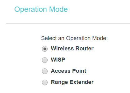
TP-Link TL-WR841N N300 WLAN Router
This router is an IoT hero
- Low cost ~ 15 €
- Low Power ~ 1.5 to 1.7 W (yeah, really)
Default DHCP settings can be used and address reservation can be configured in case you'd like to open each shelly device always on the same address. But as shelly devices run on MQTT using their device ID, fixed ip is not required.
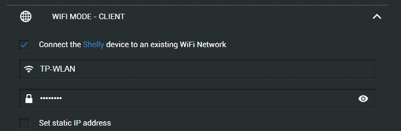
Shelly devices configuration
simple and usual as described in the manual. A shelly device creates an access point with open security at first. Once connected to its wifi Access Point, opening the url 192.168.33.1 allows to provide it the "untrusted wifi router" credentials.
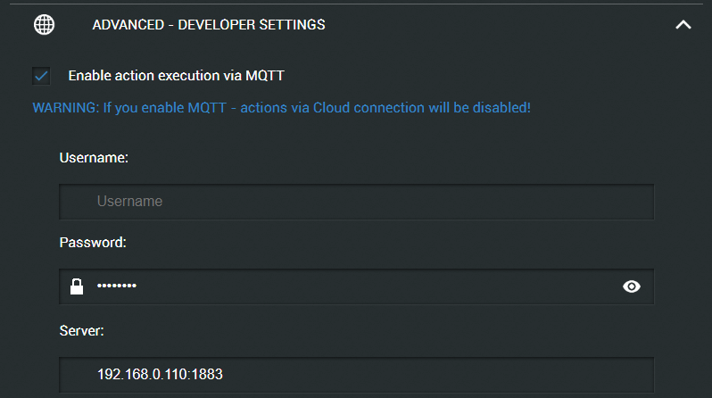
Mosquitto server
The raspberry pi MQTT broquer needs through to be in a fixed address, here "192.168.0.110" (no dns used), to be configured in the shelly devices
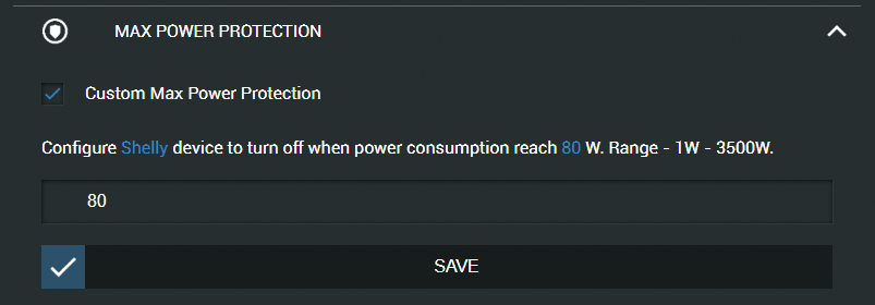
Below is an example shelly device configuration
Up to here, everything is fine and your shelly starts logging on its MQTT topic but one issue persists and we'll see in the following section how to solve it. The power has a correct value but the energy (kWh or Watt.min) stay at 0.
Explanation
The power is an instant measure, so no time required, but the energy is the accumulation of power over time. Someone could argue that the internal shelly oscillator should be accurate enough for energy accumulation, but admittedly, the energy error would be proportional to the time drift. Long story short, shelly decided to rely on time server for accurate calculation. The Network Time Protocol being too complex and an overkill in this situation, accurate decision was made to use the Simple variant "Simple Network Time Protocol". the protocol has identical queries for the subset it supports, so it can talk to a normal ntp server.
Raspberry pi as time server
sudo apt install ntp
sudo nano /etc/ntp.conf
sudo service ntp status | start | stop | restart
installing and activating a time server is very simple with the commands above. Yet one additional configuration is important when providing the time in a local network
You do not need google for that, just reading the config file can help
# If you want to provide time to your local subnet, change the next line.
# (Again, the address is an example only.)
broadcast 192.168.0.255
un commenting the line and adding the correct local network address is enough.
Until here, it still not working as yet another important step is still missing
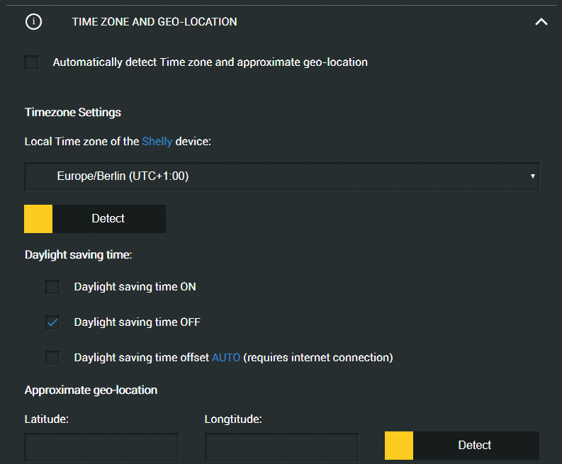
The time server does not know your time zone
Seriously ? a shelly connects to a time server and still does have no clue what time it is. Practically yes, as depending on which side of the earth you are, it could be 1am or it could be 6pm. As the shelly device is supposed to be on a local network cut from the internet, it start complaining about the time zone which should be configured not to be retried from the internet, simply entered manually, as the user usually knows in which country he lives.
unchecking all boxes that require internet is necessary
- (uncheck) Automatically detect Time zone and approximate geo-location
- (uncheck) Daylight saving time offset AUTO (requires internet connection)
so apparently a time server does not even know if daylight saving is on or off, which makes sense as each coutry have different rules for that. Hopefully the timezone gets deprecated in the near future, until then the shelly devices that needs to be operated in a local network will need to have the daylight on / off set manually when that changes.
Here shelly chould make it with a schedule entry, that would be a last enhancement for an ultimate local user experience.
Power consumption
The smart sockets being used a power monitors have tendency to be used in the power on state most of the time. Therefore shelly made a smart move by opting for the on mode to be the low power consumption state of the relay. Thanks shelly for this smart design move.
device on (W) off (W) Wemo (old version from 2016)
2.3
1.5 Shelly plug s
1.1
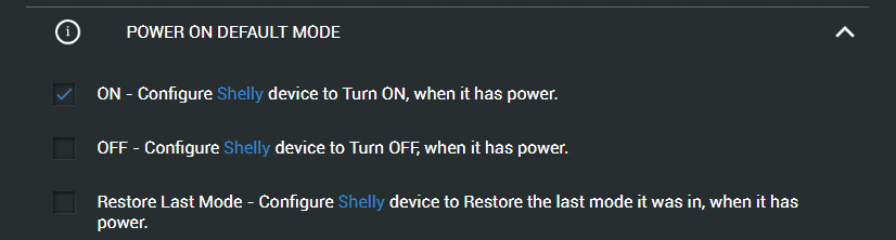
1.4 Prevent self kill
In my setup, the untrusted router is itself being monitored with other raspberry pi using a shelly device connected to it. To make the system power loss resilient, it's important to have the default power on behavior set to on. Imagine you monitor the fridge power and you have a short power outage, if this feature is not configured the damage on the fridge food content can be quite significant.
Safer is better
I cannot judge on the safety level of the shelly devices depending on used hw and sw verification measures, but if you have a feature that can activate sometime (hopefully all the time), that makes it already better than not having it.
Imagine a heater, a boiler or any device you know (as you monitor its energy consumption), you can increase its safety by setting the power protection to the lowest possible value. Households should already have protections, but if the usually allowed power is 2500W, that's already dangerous enough, so if it can be lowered on per socket basis, the safety is increased. I can't say how much, but it is.
-
Understanding Zigbee2mqtt and viewing the Zigbee graph
10/20/2019 at 13:41 • 0 commentszigbee2mqtt is a main module in Home Smart Mesh, yet it is not that easy to fulfill a reliable netwrok where a lot of situations do not match the intuitive expectations. As examples
- manually removing devices before pairing again
- manually activating joining if a router had to be out of power
So understanding what's under the hoods allows to work around such issues and maybe even help improve it.
I added the same diagrams in my raspi github as svg and original .graphml : https://github.com/HomeSmartMesh/raspi/tree/master/zigbee
The svg format of the following diagrams can be found in the link above, unfortunately hackaday does not support/allow svg, which is important for zooming such diagrams:
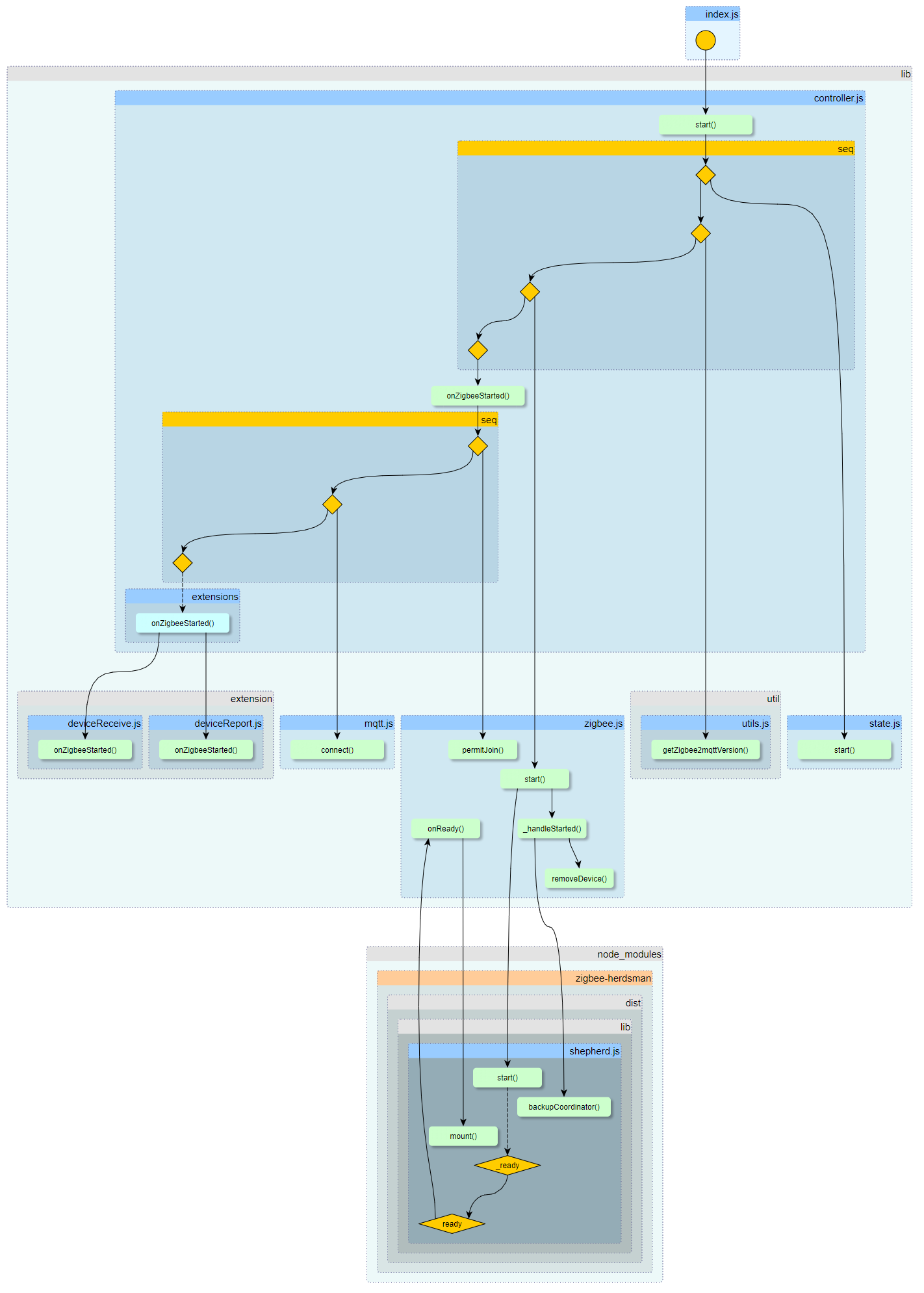
Startup
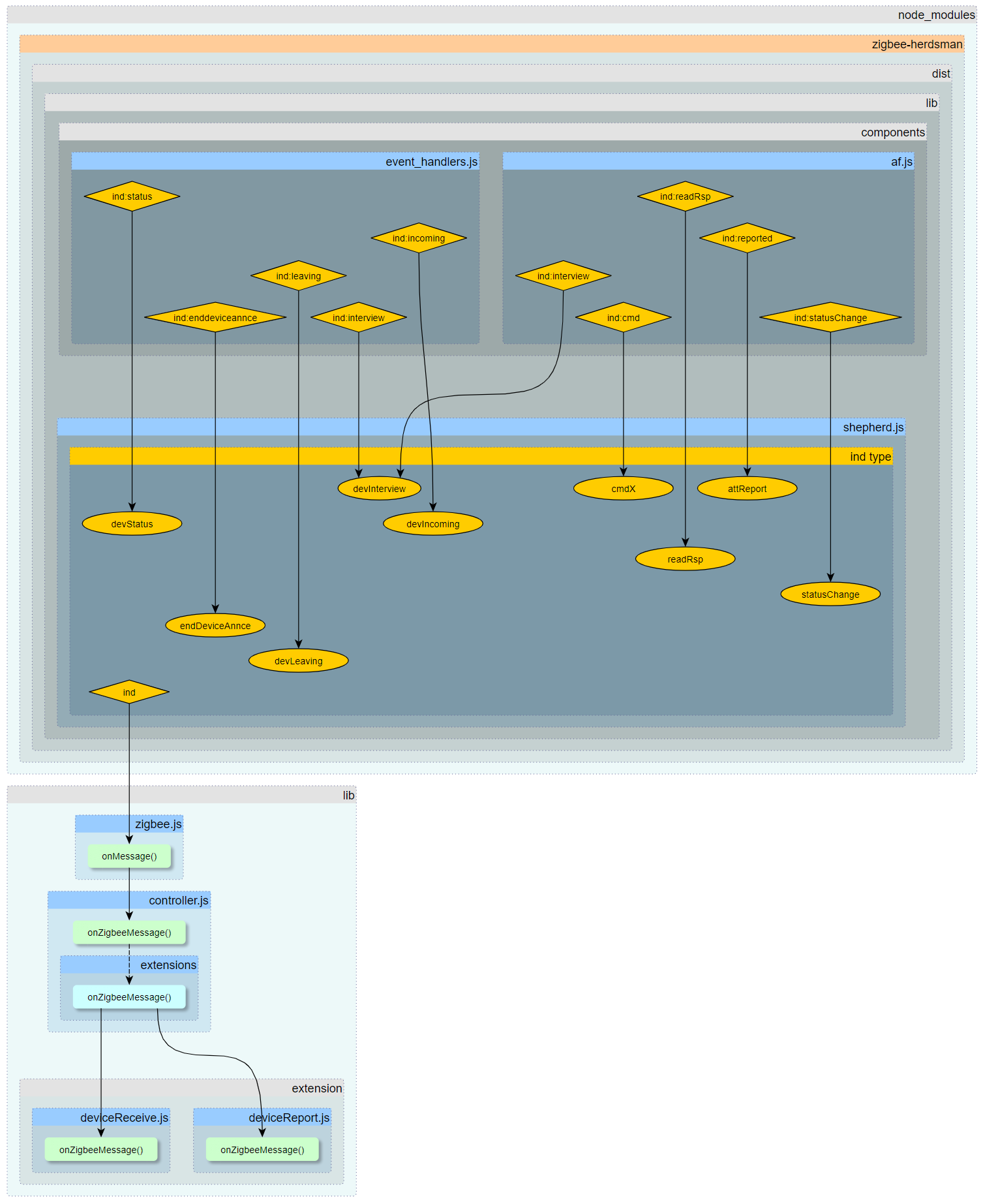
Message Events
Python to dot
what can be found in the repo is also a python tool that retrieves the graph info and store it into a file. The python is relatively unpractical in comparison to the superseding webtool of the next section
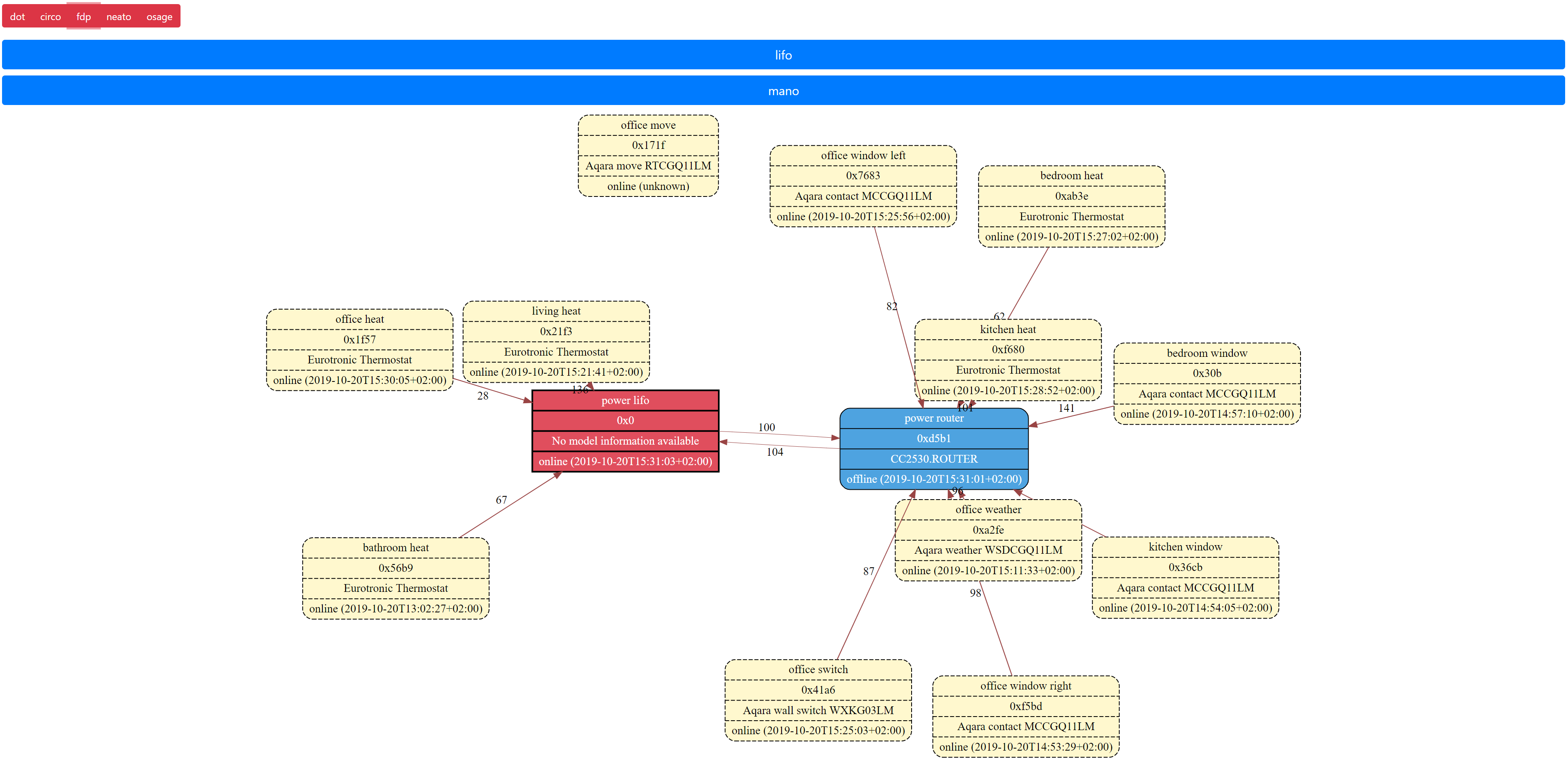
Zigbee network web viewing
This small tool is not anyhow thought to rival https://github.com/yllibed/Zigbee2MqttAssistant. But to be honest, I still did not manage to use the Zigbee2MqttAssistant due to the constraints it requires (prebuilt binaries, c sharp, lack of configuration of the prebuilt).
A mosquitto command line interface is enough for most interactivity with zigbee2mqtt, adding some aliases alos helps, so this small tool fills the gap of the last missing needed GUI for my usage, and it also brings some advantages :
- interactive SVG integration, can pan and zoom to see graphs that are huge with tiny text
- can change the graph algo layout on the fly without asking zigbee2mqtt again which produces a network scan for nothing. Different algos are more adapted to different networks
- neato : good organisation but non compact
- fdp : best average result
- circo : best for complicated graphs but explodes in large space
- can add custom buttons for those who have multiple zigbee2mqtt instances
- can add a specific algo per instance
- can add a renaming so win space as graph viewing is all about space
-
Sensors to services Deployment
09/29/2019 at 12:53 • 0 comments![]()
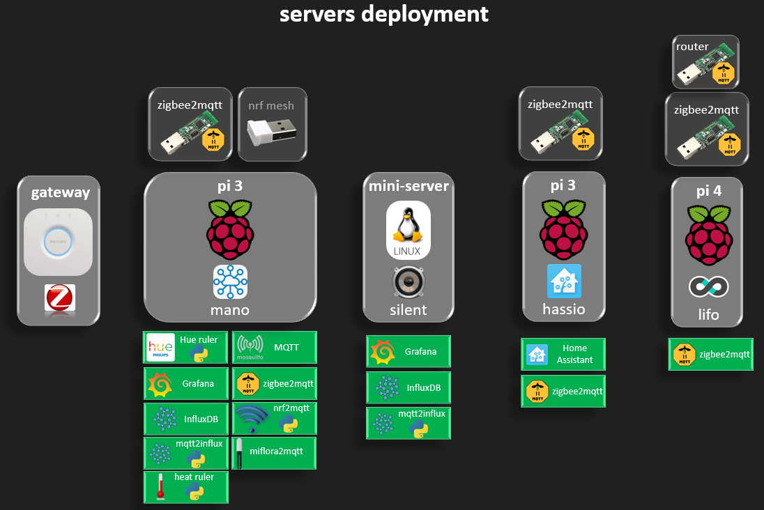
Servers
- mini-server : We begin with deployment on hardware. The mini server is a x86 ~ 20W silent PC, living room friendly, hosting the main website for a rugged access from the outside, but all smart services (grafana,...) are local network serivces.
- mano : no logic for naming is followed, just friendly host name for management. Raspberry pi have a samba share for easy logs check, the rest is ssh control. Mano has most services, standard ones (Mosquitto broquer, influxDB, Grafana, zigbee2mqtt, miflora2mqtt) and others custom developed within this project (Hue python ruler, nrf2mqtt custom python adapter, mqtt2influx simple python service and heat ruler that controls thermostat reactions)
- hassio / lifo : more experimental raspberry pi servers. Hassio has the hassio service that I find nice as a backup, it is good as interfacing everything, but the rules are more complicated than vanilla python, the viewing is nothing to compare with grafana and the control e.g. lights is quite rudimentary, it is after all hard to do everything and good.
- Hue gateway : used in local network, no account, no internet access enabled. The Hue API is quite clean and simple and python make it usage even easier. The Hue android app is also amazing and one of the main reasons why I kept the light with the Hue gateway although I could controll it through mqtt. Note that given the zigbee standard, all sorts of zigbee light bulbs can be attached to the gateway and not only those of the manufacturer, which is quite fair.
- remote access : all services are remotely used through a vpn access, which relaxes all need for security that should not be mishandled by diy development rather collected in a (relatively) reliable interface.
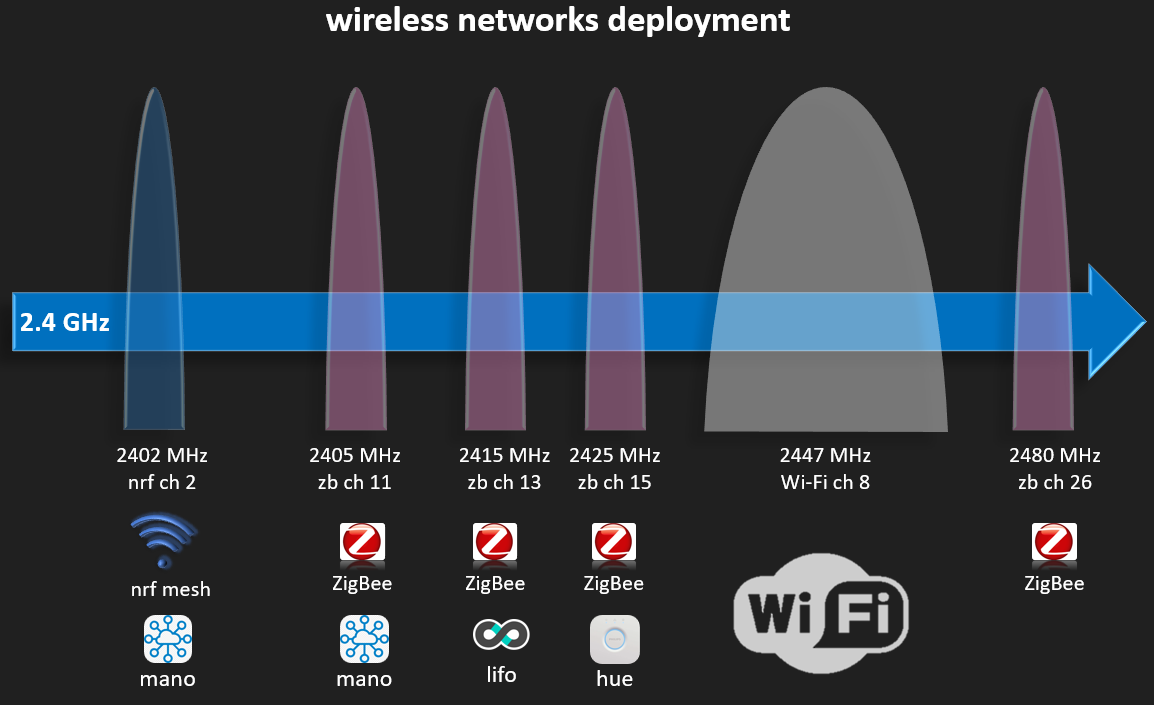
Wireless networks
One of the most annoying feature of wireless network is the shared resources (the air - or the void). Users can rarely see on which channel is the wifi network, and it is left for automated selection by the router. Especially in case of intensive experimental environment, it is important to allocate frequency space for every network to avoid interference's. Pairing a zigbee device can be much less reliable in case of high interference, also battery usage as the zigbee is an acknowledged protocol (over IEEE 802.15.4) and the simple no-ack protocols would see more data drops.
The wifi has a wider bandwidth, so it's good to leave more than one zigbee channel free around it. The diagram is only illustrative, the bandwidth depends also on the router configuration.
Bluetooth does not appear here although the miflora devices are bluetooth. It is narrower than zigbee (shorter range smaller bandwidth) and always hopping so it freaking disturb a little everywhere. A further analysis could check detailed impact, more info on the matter can be found in references such as : https://help.turningtechnologies.com/PDF/Hardware/RFInteroperabilityDoc.pdf
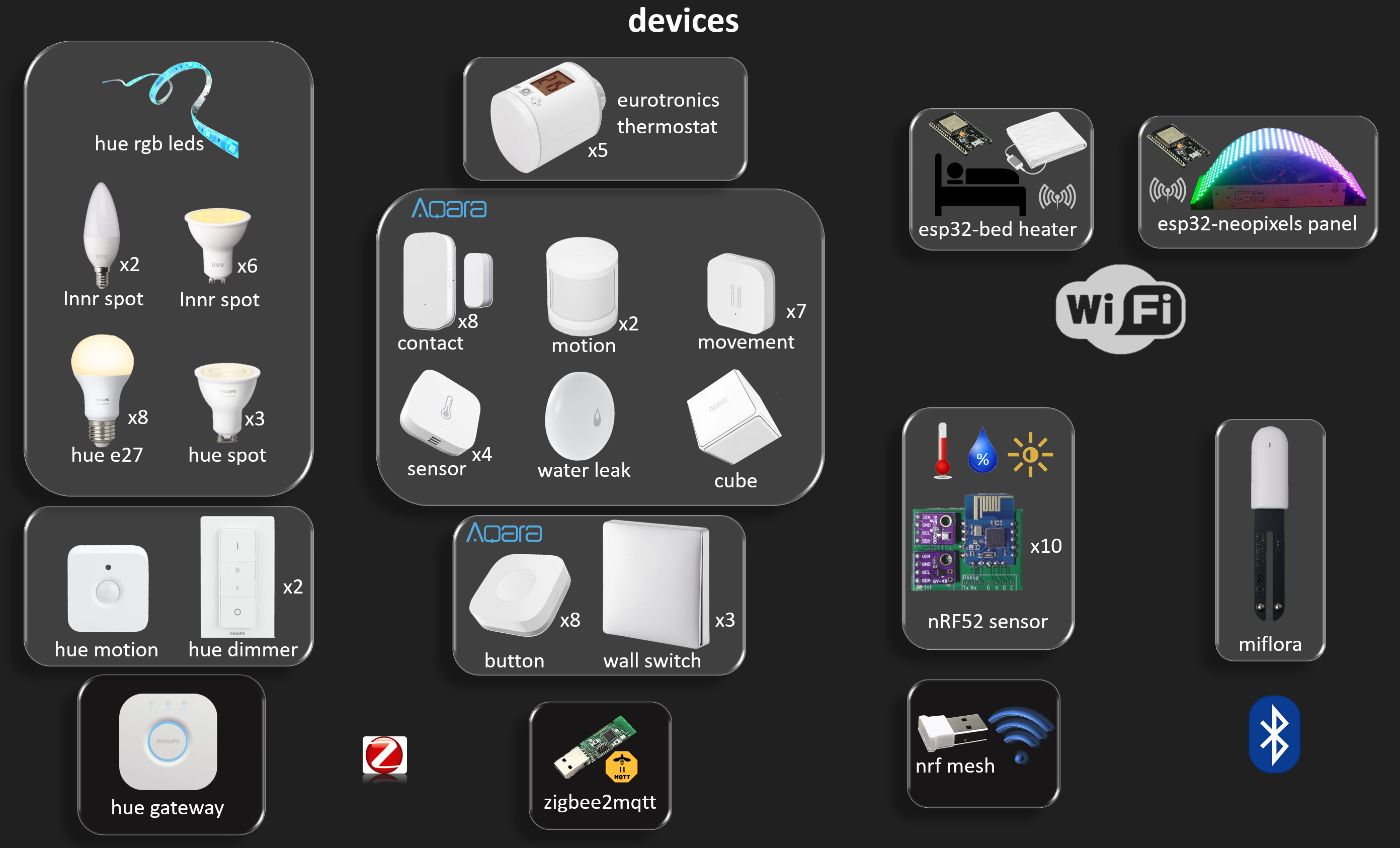
Devices deployment
Aaround a hundred devices to be managed would make every day life more confusing than helping if not seamlessly integrated in the environment. Changing batteries is also required, luckily devices hold from 6 months (the custom made ones) to around 3 years at least for the others. What is important on the other hand is a low battery alert to avoid having to keep checking batteries level very often.
Philips hue lighting are quire reliable, inter-operable with Innr, and the pure white ones (not colored) are quite cheap. Zigbee include devices association so that the dimmer can talk to the light directly without the gateway, but that is a useless feature. In about two years of usage, I did had a failure once when for some reason I had to re-pair a dimmer. Using independent buttons (aqara) to switch hue light through the hue api have a reliability of Ethernet network, in my case no wifi used for the raspberry pi controlling the light and luckily the hue gateway also has Ethernet plug. So other than de-bouncing bugs from early maturity, the system works quite reliably and is very responsive.
Hue dimmer vs aqara button vs aqara wall switch
The Hue dimmer is elegant, yet misses one point for long press configuration. Having one function for first and one for second press is not practical if first press is most common normal full lighting and second is low level lighting. This issue is solved with aqara single click vs long press for low lighting. The wall switch have similar functions as the button, but is much nicer on the wall, yet the button is more silent in usage.
Eurotronics and aqara contacts
It is practical to set a heating cut when a window is open, see more details on how aqara are notifying the eurotronics thermostat in this log :
The Eurotronics thermostats have excellent functionality, still experimenting first weeks of battery life. They do not replace a temperature sensor as they only report the temperature when asked for a function otherwise randomly every few hours. When they report the temperature, they report three of it (see details in zigbee2mqtt wiki).
wifi is still the master of home automation and zigbee interoperability
Let's not forget the basics, zigbee did not invent home automation, rather the corner cases where low power is required. For everything that already has a permanent power access, wifi is much simpler to use. It is true that depending on the network, wifi might have a bad response time which is very likely to happen most of the time, therefore zigbee or custom would have the niche advantage that networks are not so polluted as wifi. But this assumption is less valid every day when zigbee networks get flooded with devices. In theory zigbee get hold millions of devices, in practice with limited memory implementations zigbee2mqtt recommends only 20 to 40.
As conclusion interoperability is of major concerns when relying on zigbee for vital functionalities such as lighting.
wifi devices light and heat
The bed heater is a simple ESP32 with an mqtt interface that takes a percentage (with steps of 10%) and sets the heating accordingly. It also features and mandatory power off after one hour.
The RGB led panel has its own project page on #Neopixels Animations on ESP32 MQTT Json Webapp . It is quite a fancy ambient light with no equivalent on the market, as every LED is addressable and the mqtt commands take requests for wave frequencies and colors, that prevents a huge traffic of an app that would have to download complete LEDs sequences. So the light stays at vectors level and do not involve videos. It has not been deployed for usage with aqara devices yet, but this should be quite simple, e.g. one press for ocean animation, long press for savana animation running one hour.
nRF52 sensors
The nRF52 sensors have their own project entry on #nRF52 Sensors Mesh Network . It is quite remarkable that they have no equivalent on the market yet. The aqara temperature and humidity does not feature light and has a much lower resolution (agreed not always necessary) but the high resolution can allow new ways of learning events from temperature variation signals not only from rough changes, that high resolution signal can calculate the heat constant or knowing the heat capacity of the room, to calculate the attack vector such as opened window, or opened fridge. This network does not feature any configuration, devices are flashed with their ids. So no pairing pain, but also much less practicle for real use cases as there is no automatic channels selection for example. Also no timing synchronization, even no acknowledge. All of this simplification result in a very simple software stack (one file with few functions).
miflora
I hesitated to add it to the list, as it's not a mesh after all, and bluetooth range is lower than zigbee, but it is a home automation sensor, and it is still possible to compensate than by having one raspberry pi per region of the house.
Applications deployment
... yet to be witten...
how to view and control what, with which app / web app and which technology is used behind
-
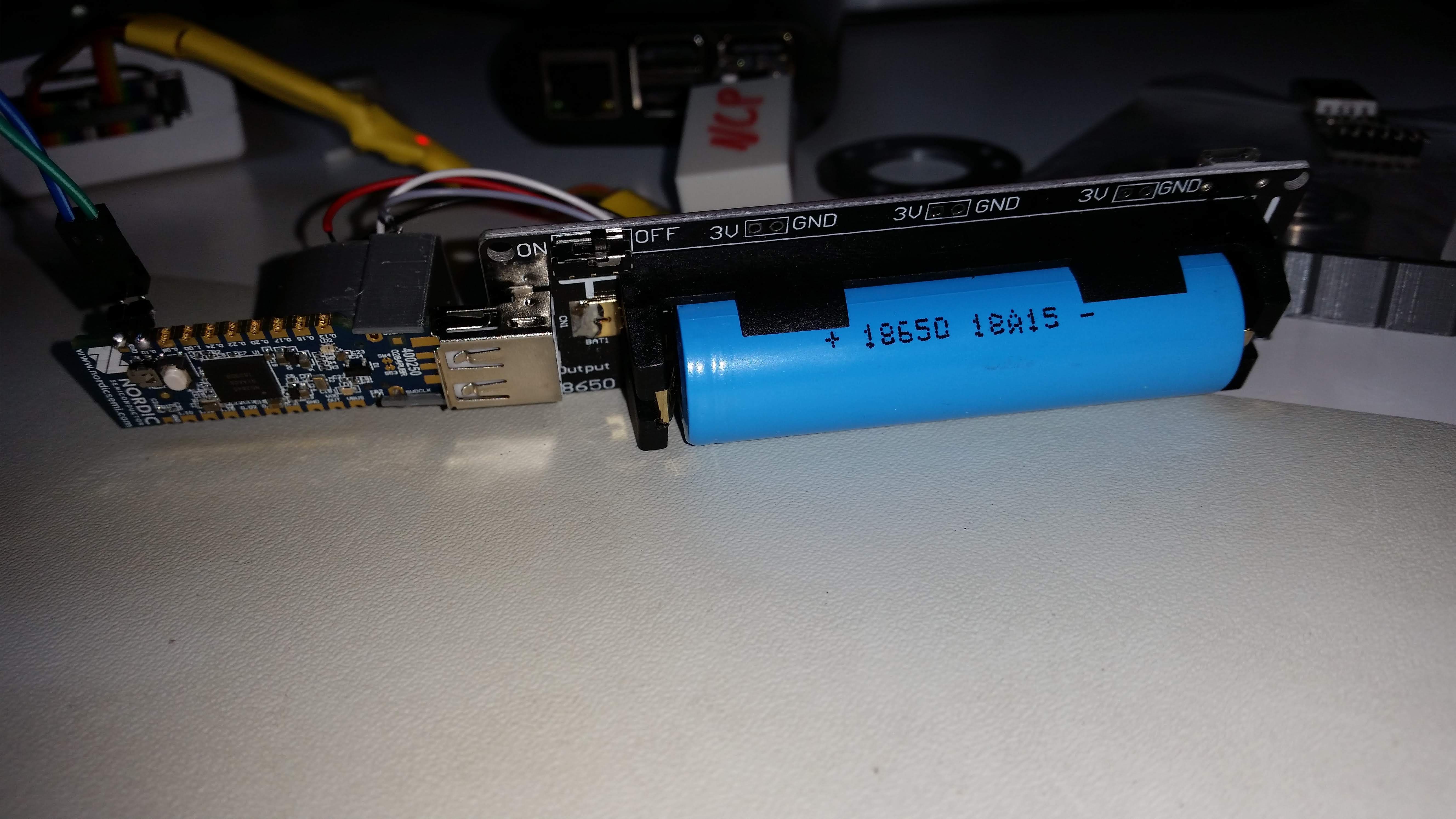
nRF52840-Dongle hacking
01/13/2019 at 15:43 • 0 commentsThe nrf dongle has many stones on its hacking path.
- UICR.REGOUT has to be set to 3v3
Default to do so might brick it, and rescue needs high voltage jumpers switch explanation from Nordic here
- UICR.NFCPINS
Using the simplest pio, with my luck on falling over pio 0.10, of course it does not work, you need to set the UICR of NFCPINS PROTECT to disable.
- LEDS don't blink
although defined with the right functions LED1_G,... into pca10059.h, when using
bsp_board_led_on() indexes from 0 to nb leds have to be passed and not the led defines !!!
- Ground mass
without a bigger ground mass, the cpu keeps getting hard faults, so when debugging with swd I had to connect a usb charger without powering it on, just for bigger ground mass.
![]()
-
Node-red : from Aqara motion button to esp32 RGB Leds
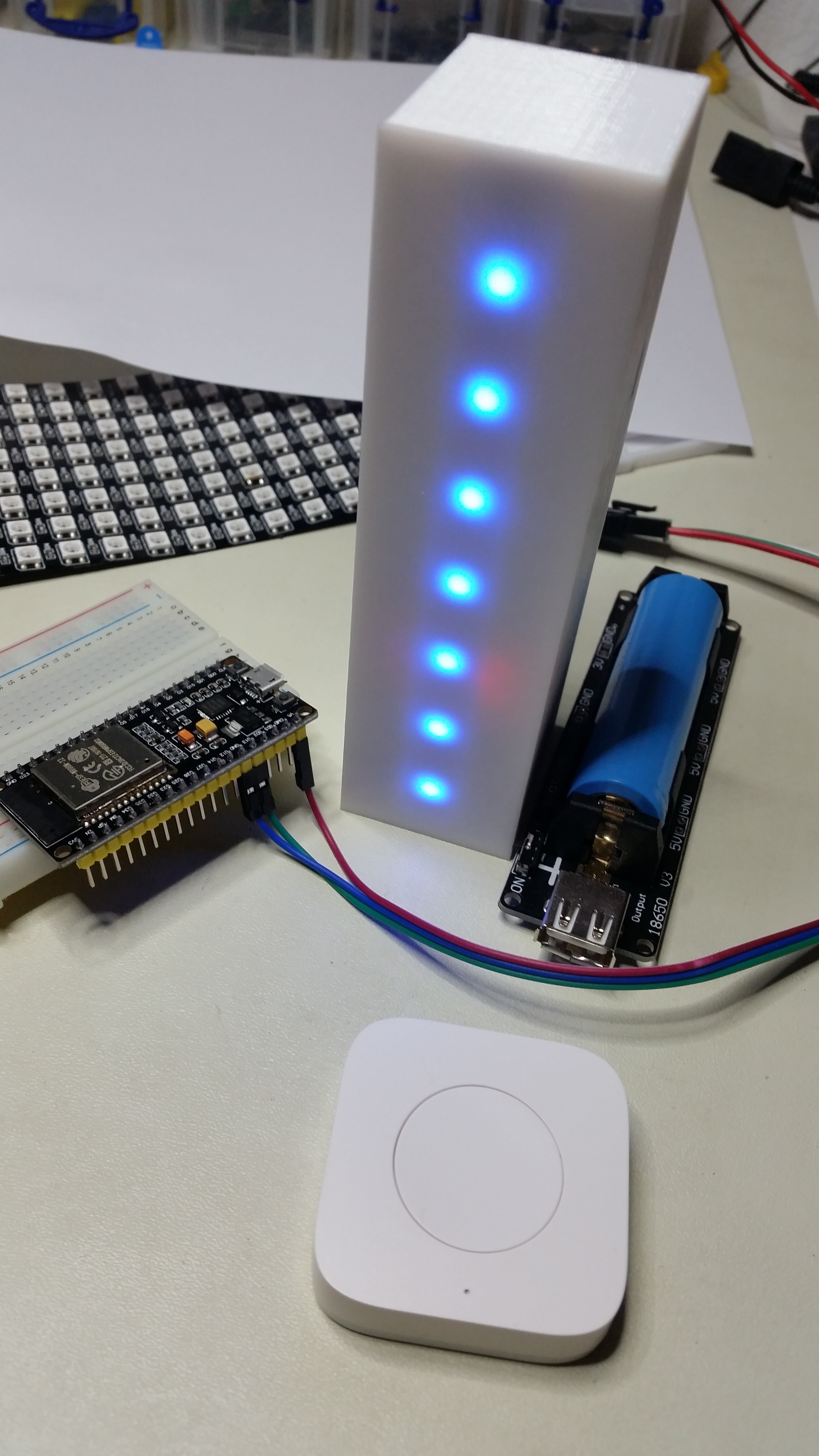
11/18/2018 at 19:45 • 0 commentsBelow, an esp32, like the one visble on the test board, is hidden in the white 3d printed tower. 7 WS2812B have been united for the purpose. An 18650 battery power module like the one visible on the right has been used inside the tower.
![]()
Everything becomes easy when iot unite around MQTT to talk the same language. The Aqara motion button has been paired with zigbee2mqtt and picked up directly from there by node-red. I developed an esp32 mqtt application that takes json payloads to turn the grb leds with on and off. The esp32 is developed using the esp-idf, and the source code is available on github : https://github.com/HomeSmartMesh/esp32_iot/tree/master/rgb_led
For those not familiar with zigbee2mqtt, the aqara button click produce such publish :
zigbee2mqtt/motion button {"click":"single","battery":"100.00","voltage":3055,"linkquality":92}and to turn all leds red by command line (broquer on localhost) :
mosquitto_pub -t 'esp/rgb led/all' -m '{"red":60,"green":0,"blue":0}'And the rest of the rules can either be handled by node-red as the example above, or by python for a much more flexible rules. Note that direct rules connections as simpler with node-red, but as soon as some logic is needed, then even for beginners python is more readable than node-red. github for python rules example : https://github.com/nRFMesh/nRF52_Mesh/blob/master/raspi/esp32/esp32.py
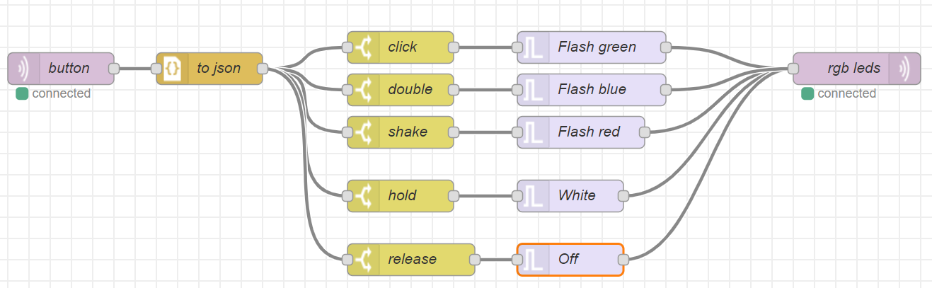
It might be me, but it took me quite some effort to get through using node-red for a little bit advanced not too advanced examples, so I show some screenshot for very quick start with node-red.
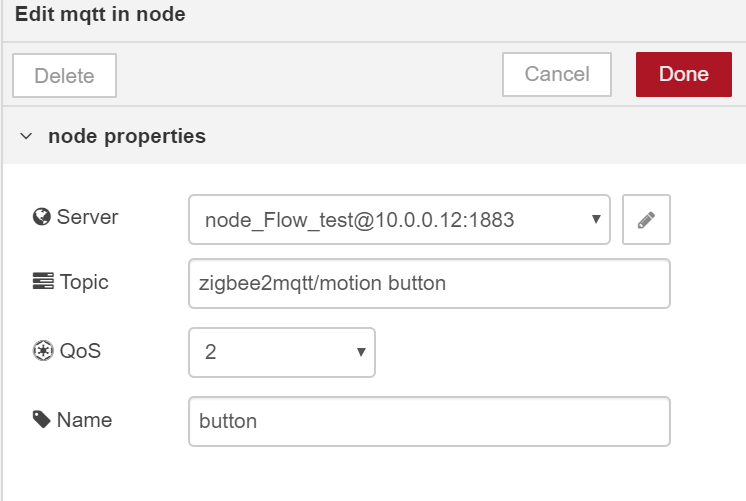
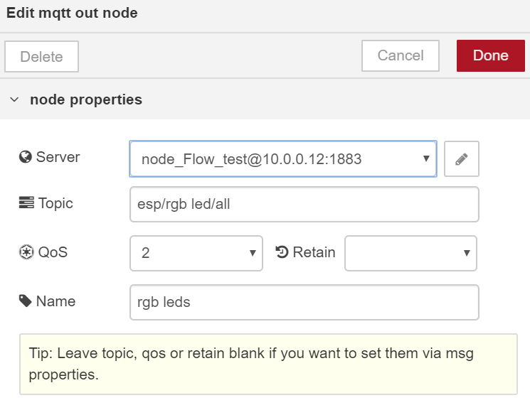
The input is an mqtt input with the broquer address configuration where mosquitto is running :
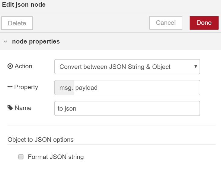
I used json node with this config :
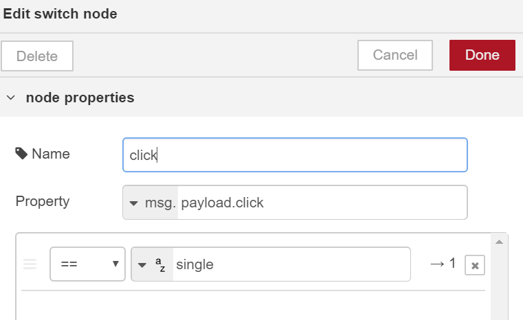
Then a switch node that selects which event has happened in the button :
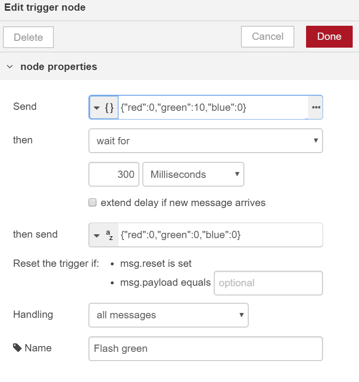
The Flash green example :
Then the mqtt output to the esp topic :
Conclusion
For connecting events to actions, node-red is really a wonderful tool that bring up visibility to your iot network.
When playing with timing already, for generating 300 ms or 500 ms pulses, that's where node-red frontier stops. The ethernet and mosquitto jitter is much higher than such time scales, so ideally for next time, I'll implement a flash function in the esp32 directly and special topic for it so that node-red only need to send one message for flashing and not the start and the end of it.
I wish I could rid of that "to json" box, and maybe use functions in the future, less boxes is always good.
-
nRF24L01 Flood Mesh Protocol
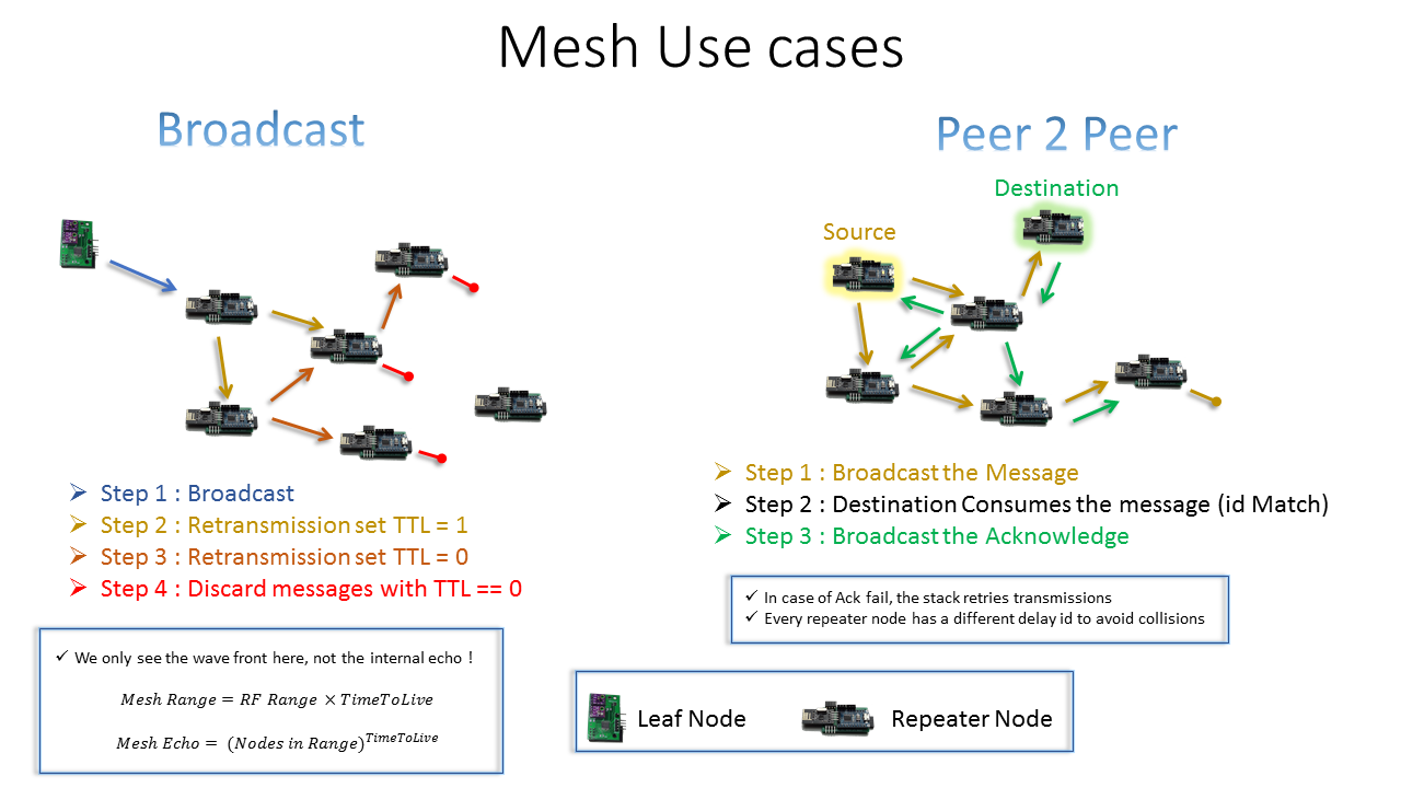
05/14/2017 at 12:20 • 0 commentsMesh use cases
before talking too much about mesh concepts, let's see end results what useful things can we get of this ?
![]() Flood versus Routing
Flood versus RoutingThis is a Flood mesh type opposed to routing mesh types.
- With a Flood mesh, Zero configuration is required, just throw nodes in, every node has its id.
- A Peer to peer message just need to know the destination id, the stack handles an end to end acknowledge with retries if necessary.
- This type of mesh is router less, which means it get advantages such as
- the nodes do not need routing tables to define the shortest path
- which is also hard to configure if the nodes move or would have to be identified on startup.
- A routing mesh would also require a central server or duplication of management in every node acting as a server.
- But there's no magic in here, a Flood Mesh have some compromises to do which might be completely irrelevant in some scenarios.
- The mesh Range is as wide as you have nodes and capacity to live through jumps, yes but then why don't we use a huge time to live for an endless range ?
- Well the problem is the echo, as the nodes have no routing info, they will keep repeating messages to each other, even back to those they got the messages from !!!
- This Echo is born from the flood concept itself, it reaches all the nodes around who keep singing along for one single message until that message dies.
- During a time to live group repetition, all the impacted network is busy with that single message. which highly increases collision chances and messages loss.
- In the scenario of a home, this compromise is not of much relevance as you barely need a single repetition jump, one Time To Live can get you through a villa, and two through a huge building, this is not fit for a city network as its name says this is a #Home Smart Mesh.
- As two nodes listen to an RF message at exactly the same time, they are likely to react with a repetition at exactly the same time as well. To avoid that, every node uses a per id delay configuration to repeat the message with a shift in time.
Leaf versus Repeater Nodes
Leaf Nodes are acting like beacons. They are wireless low power sensors that cannot keep listening, thus the frequent Broadcast for them is strategically a better compromise than a Message to a server. The unpredictable time listening waiting for the acknowledge can allow to re transmit much more frequently with the same power budget. Additionally, these nodes do not need to be configured to know the server Id.
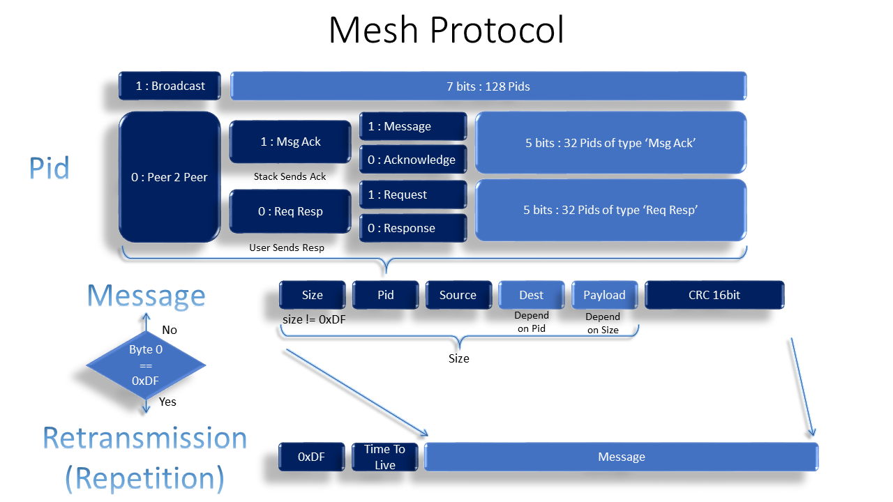
The Mesh Protocol
![]()
- This Mesh protocol was custom designed to take advantages of the hardware it was designed with. The reason it is different than others is simply that the RF transceiver nRF24L01+ is much cheaper. With up to x10 times cheaper, well you get some side effects such as packet size limitation. With 32 bytes, if your protocol header is big, well then you have no more room for a payload.
- The protocol above uses only 8 Bytes at max while fulfilling all conditions of end to end addressing, redundancy checks, acknowledgment and repetitions.
- By design, messages do not have time stamps nor sequence ids, which let the multiple repetitions reception be filtered at the destination side. That means that yes, filtering time has to be slightly higher than the Flood echo time, and the sensors broadcast frequency must be slightly lower than the listeners filtering time.
- The only complexity we get here is in the Pid that has been compacted to handle both the message type (e.g. Temperature, rgb color request,...) and the message status, if it is a broadcast or in case of peer to peer Request or response.
- The source and destination being part of the user software protocol solves the problem of all radio transceivers that have hardware pipes with addresses. Those addresses have to be configured depending on the network and the number of pipes is limited for the nRF24L01 to 5. Well, it is nicer to have more than 5 nodes in your mesh !!!
- The HW acknowledge of the shock-burst is also a waste of resources in a mesh use case with a flood concept as it is a point to point acknowledge opposed to the software one we use which is an end to end acknowledge. The point to point acknowledge is useless here because if two nodes might be interested by repeating the message then which one should send back this acknowledge ? The end to end acknowledge is abstracted from the mesh protocol and the destination decides to send it back as another normal message.
- The CRC is only calculated once and is an end to end CRC, which means that we do not care if a single step has failed as the source is expecting a feedback and would retry otherwise. That makes the intermediate repeaters more efficient and faster to reduce network occupancy time.
- Note that the repeaters can read the message content to know the complete repeated message size which is here the third byte + 2.
- The first byte then limits the size of the messages to a lower value than the id itself, buy here as we use the nRF24L01+ with 32 bytes of payload size, it is safe to use even more bits from the first byte, or scale to another transceiver for up to 222 byte payload.
Security and interoperability
- Security is not forgotten, but omitted here, as not required by this simple standard and left to further customization inside the user's payload. If it is a light sensor which information can also be spied through a window within RF broadcast reach, then why bother protecting it ? But let us be careful here in a way that the server bridge who have internet access must be highly secured that is out of scope of the RF network. Ideally the server access ports are not opened from the router, remote access to the server can for example use a VPN which was the solution I opted for not to bother with custom coded SSL. Note that VPN does not require a third party provider if you get a router that supports the functionality.
- If your neighbor has the same system, you're also covered, as you have 5 bytes of HW addresses that will be shared by all of your nodes, to have a very unique mesh network.
Yet another protocol to for IoT ?
- In a quick evolving IoT scenery we're not lacking network protocol, so why using a custom one ?
- Standards want to cover a big number of use cases which makes them either inefficient or complex, or both.
- Wifi requires considerable power and sw stack size.
- Bluetooth brings the mesh in its version 5, wait few years till you get devices supporting it, who know how much these would cost given the increased requirements in payload size,...
- Zigbee hits the target as it was designed for it, but how much does any 802.15.4 transceiver cost, you're lucky if you get one just x10 times more expensive than the nRF24L01+.
- This Home Smart Mesh Flood implementation in a running bridge application uses overall barely 4 KB including text logs and multiple unused functions (modules non optimized), which makes it fit for ultra low cost devices.
- Without mentioning a last but not least argument, which is simplicity and speed of development which even fits DIY context, as the whole thing can be described in one slide as presented above.
-
Smart LED Panel - MQTT to x216 WS2812B
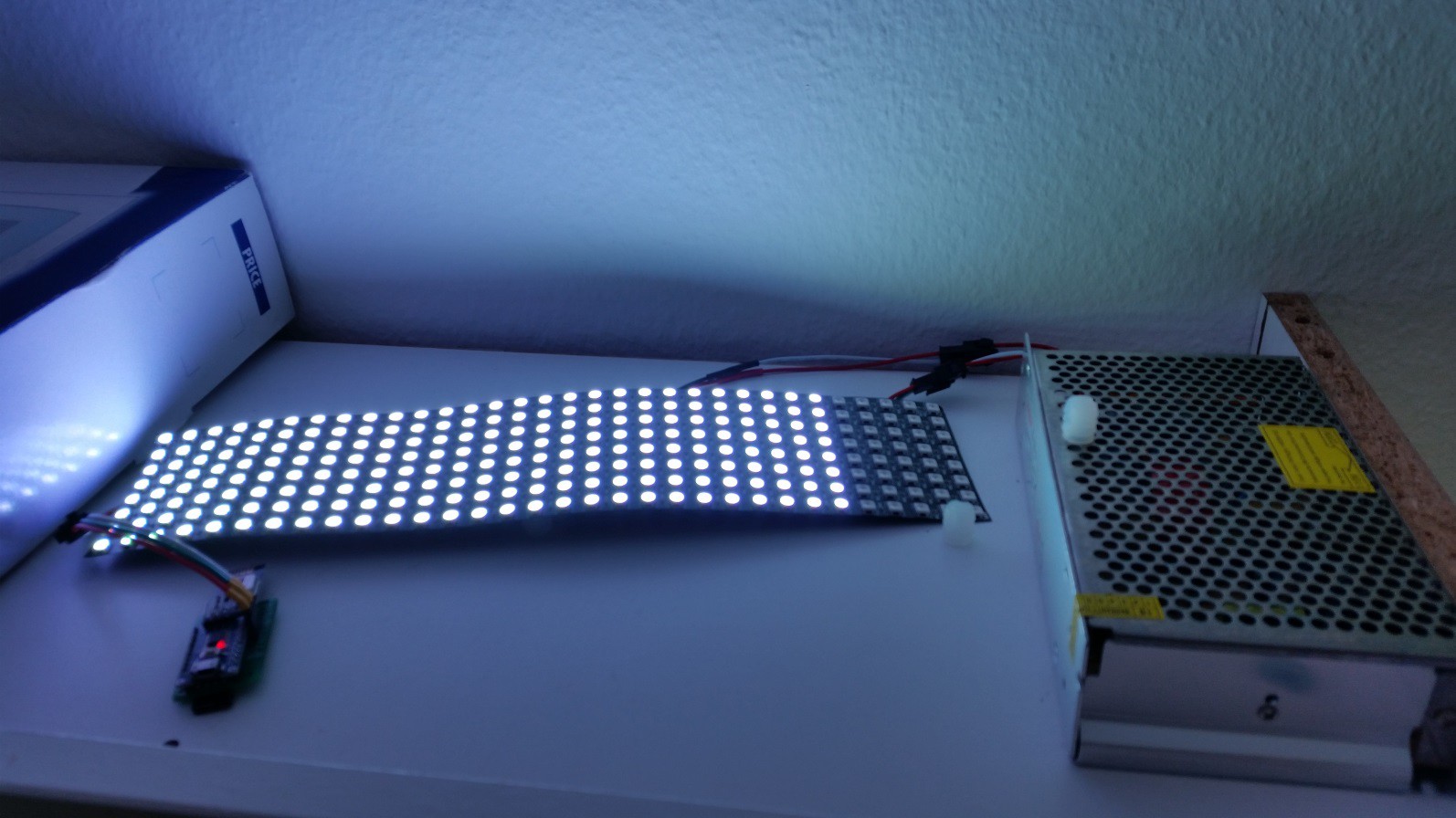
04/29/2017 at 13:32 • 0 commentsDemo
- This demo is just a picture where the RGB Panel is switched on next to its STM8S_RF_Dongle which is here an RF to WS2812B converter.
![]()
How is this working ?
- The STM8 firmware to control the WS2812B has already been presented in this Log and the LED series up to 60 here
- Here we push the number of LEDs up to x216, it could go up to x220 but then it would not be aligned any more. The panel offer up to x256 LEDs but the STM8S memory of 1KB reaches its limit here. For a single color I could simply rework the function to lightup an unlimited number of WS2812B, but we would then loose the option of displaying figures or messages.
- Every WS2812B consumes up to 60 mA, so for 256 LEDs that's no kidding 15 Amps !!!! Thus the transformer next to it can go up to 20 Amps !! note that this might be dangerous if you use less powerful transformers !! From safety perspective, I'm currently using a manual switch in addition, I would not recommend such an installation without a relay that fully cuts out the current when not in use!!!!
- The radio protocol is very simple and provided in the libraries through the WS2812B.c it looks like this :
PID - NodeID - R - G - B - CRCMQTT Control
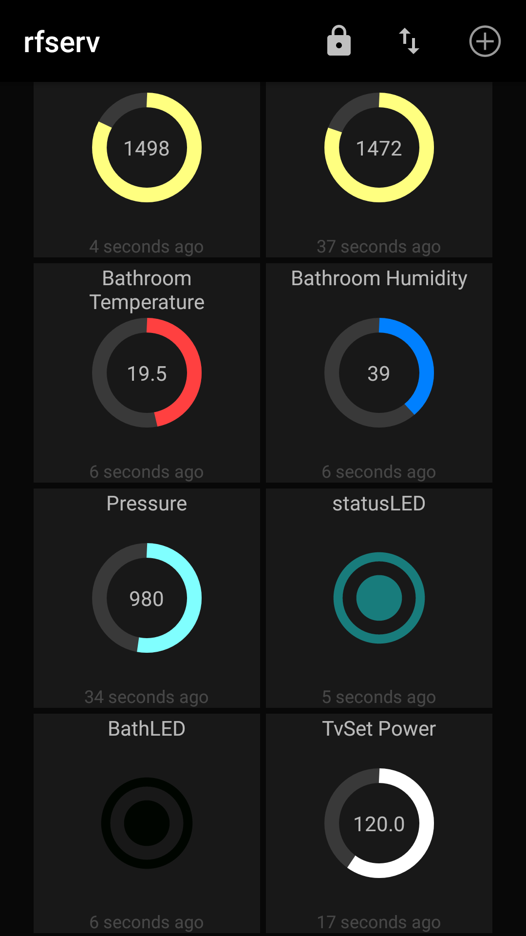
For convenience here, I used a ready Android application MQTT Dash which worked out of the box once I used the topic payload format for colors which is the #RRGGBB (e.g #FFFFFF for white). It is enough to program the right topic address (e.g. Nodes/10/RGB), this app is cool as it even provides colors pickers.
![]()
By the way, we can see here a TVSet Power as well which is an off the shelf Wemo switch connected through OpenHAB2 and MQTT.
Conclusion
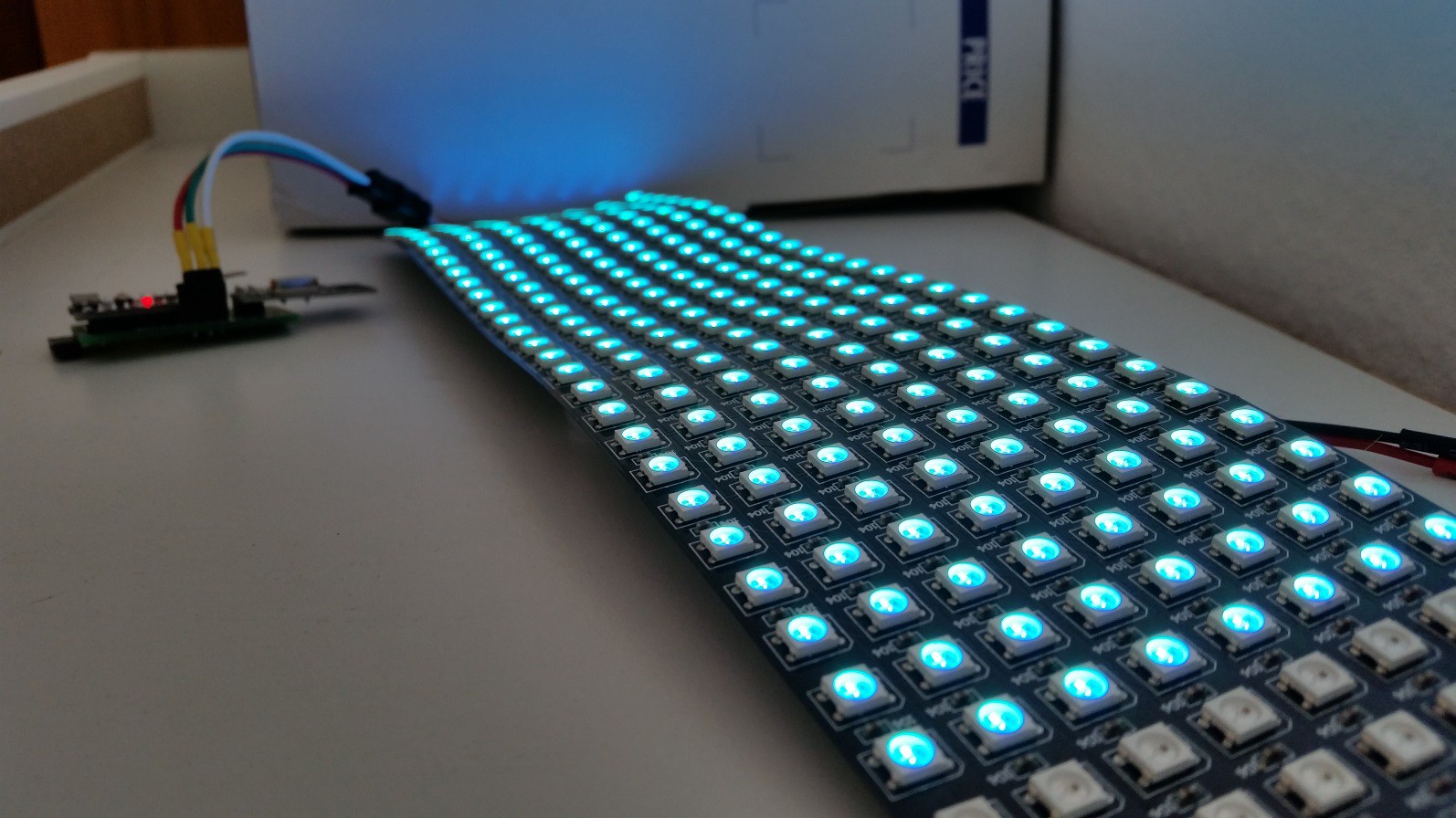
If you need just brighter light for your room, do not use this Panel which is more valuable than that, I plan to shit it to a central messaging notifiers and use it to display text and symbols.
![]()
-
Completely Hackable IoT dashboard
04/26/2017 at 19:09 • 0 commentsDemo
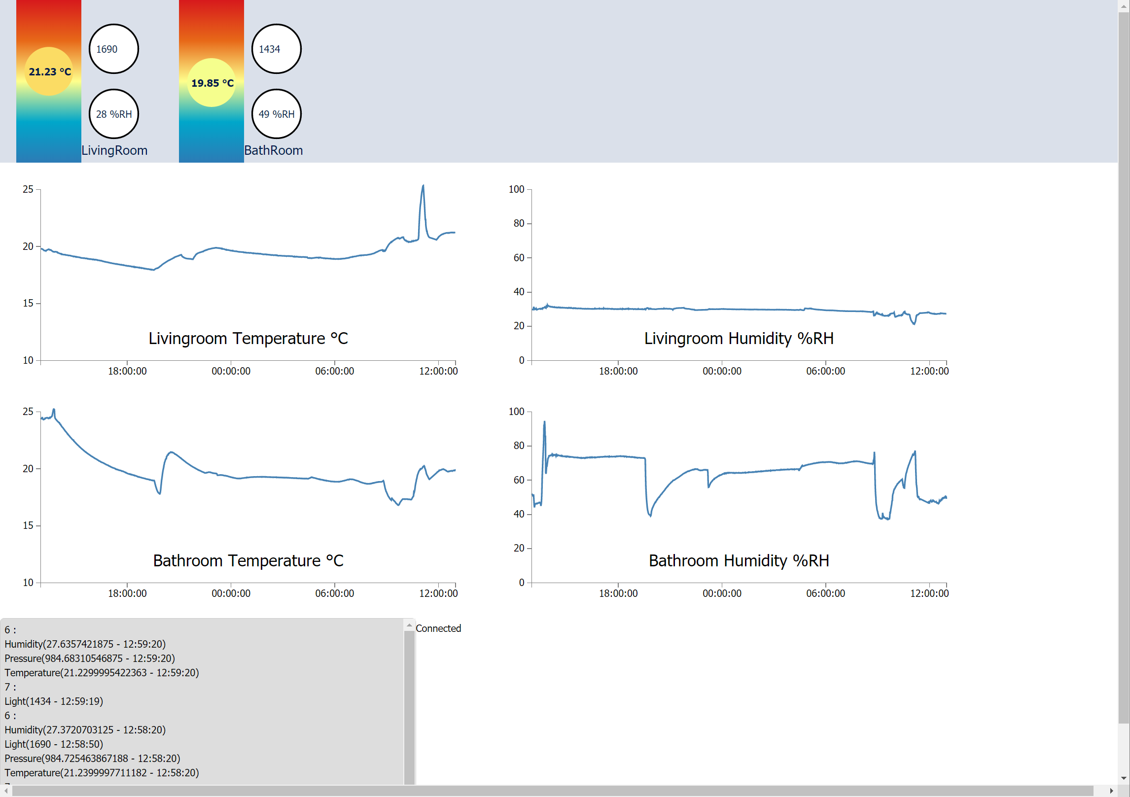
- We can see here how the dashboard looks like, definitely not impressive but the good news is that it is completely hackable !!!
![]()
So we can see there bullets going up with the temperature changing color accordingly, note that the color matches the gradient position of the rectangle it's in. The curves show the last 24 h, still planning to add dynamic real time animations, the technology allows but not the time. This page shows an ugly text debug window at the bottom helping me to check all received notifications.
What's behind this ?
- first of all, this is web, only web, html5 is helping, javascript is improving and the tools coming with it as well to make it a descent programming language.
- I struggled looking for ready javascript libraries to show graphs such as highcharts or amcharts they look nice, but not only you get stuck with licence stuff but you cannot edit it to very customized display, the right choice ended on d3js
D3js
- d3js is a wrapper library around the svg standard which just makes selections easier and have a lot of helper functions and examples
- The learning curve is long, but I highly recommend it to those who want to understand the web technology and not simply use it.
Websockets
- Another major improvement in the web, after struggling for server side events with comets or other alien like mechanisms, the websocket restart from scratch and provide an efficient tool already known and proved, the hack behind it is to start as an http request, and then upgrade to a websocket
Poco
- I know javascript is fancy, I know python is cool, sorry to say this but c++ is easier, here I'm not talking about personal preference. Not about writing code only which is obviously faster if you omit declarations, but I'm talking about the effort you spend from when you start writing your code till you get it running as you expect.
- That is why I opted for a C++ application for netwroking where Poco marvelously does the trick. I hesitated between boost io and poco, then opted for poco as it is more than a library as it provides even application class, log and other helpers.
Security
- Some of you might wonder how would I secure this, with all polemics we read about every mentioning IoT devices being hacked, and I do yes access this remotely.
- VPN : yes, the answer is simple, let us not re-invent the wheel, plus I have no time to spending updating every new patch of my authentication web interface. I admit here the solution was expensive, a VPN enabled router, but it's a single time payment for a multipurpose router and the result is independent from any 3rd party (other than simple domain name redirection).
- It is important to note here how users can and must own their IoT devices by using tools that do not require third parties services that only work with registrations or even worse requiring active internet connections, here latency and confidentiality have to be taken into account.
Some Javascript
I learned how to split my javascript in more than one file (not trivial, yes, I'm serious), so I isolated the usage of the d3js graphic elements from a simple interface:
var StatusParams =
{
	svgID : "#StatusDisp",
	data  :
	[
		{ x: 100, y: 100, r: 20, color: "Blue",
			Temperature : 26, Light : 500,
			Name : "LivingRoom"
		},
		{ x: 300, y: 100, r: 20, color: "Blue",
			Temperature : 26, Light : 500,
			Name : "BathRoom"
		},
		{ x: 500, y: 100, r: 20, color: "Blue",
			Temperature : 26, Light : 500,
			Name : "Balcony"
		}
	]
};

var nmap = {6 : 0,
			7 : 1,
			16 : 2};

//---------------------------------------------------------------------------
//					Time Chart
//---------------------------------------------------------------------------
var now = Date.now();
var start_disp = now - 24*60*60*1000;//1 day
var ChartsParamsList =
[
	{
		svgID : "#ChartLivTemp",
		scale_x_domain : [start_disp,now],
		scale_y_domain : [10,25],
		NodeId : 6,
		SensorName : "Temperature",
		Label : "Livingroom Temperature °C"
	},
	{
		svgID : "#ChartLivHum",
		scale_x_domain : [start_disp,now],
		scale_y_domain : [0,100],
		NodeId : 6,
		SensorName : "Humidity",
		Label : "Livingroom Humidity %RH"
	},
Then let's call it the main function is simply initializing using these tablesvar MyPanel = new StatusPanel(StatusParams); var MyChartList = new TimeChartsList(ChartsParamsList); var reqList = [statusReq].concat(MyChartList.getAllRequestsDuration()); initWebsocket(reqList,MyPanel,MyChartList);d3js has excellent doc and tutorials so I won't detail it here
The source code is of course available with the rest of the IoT_Framework here in github
Another Screenshot
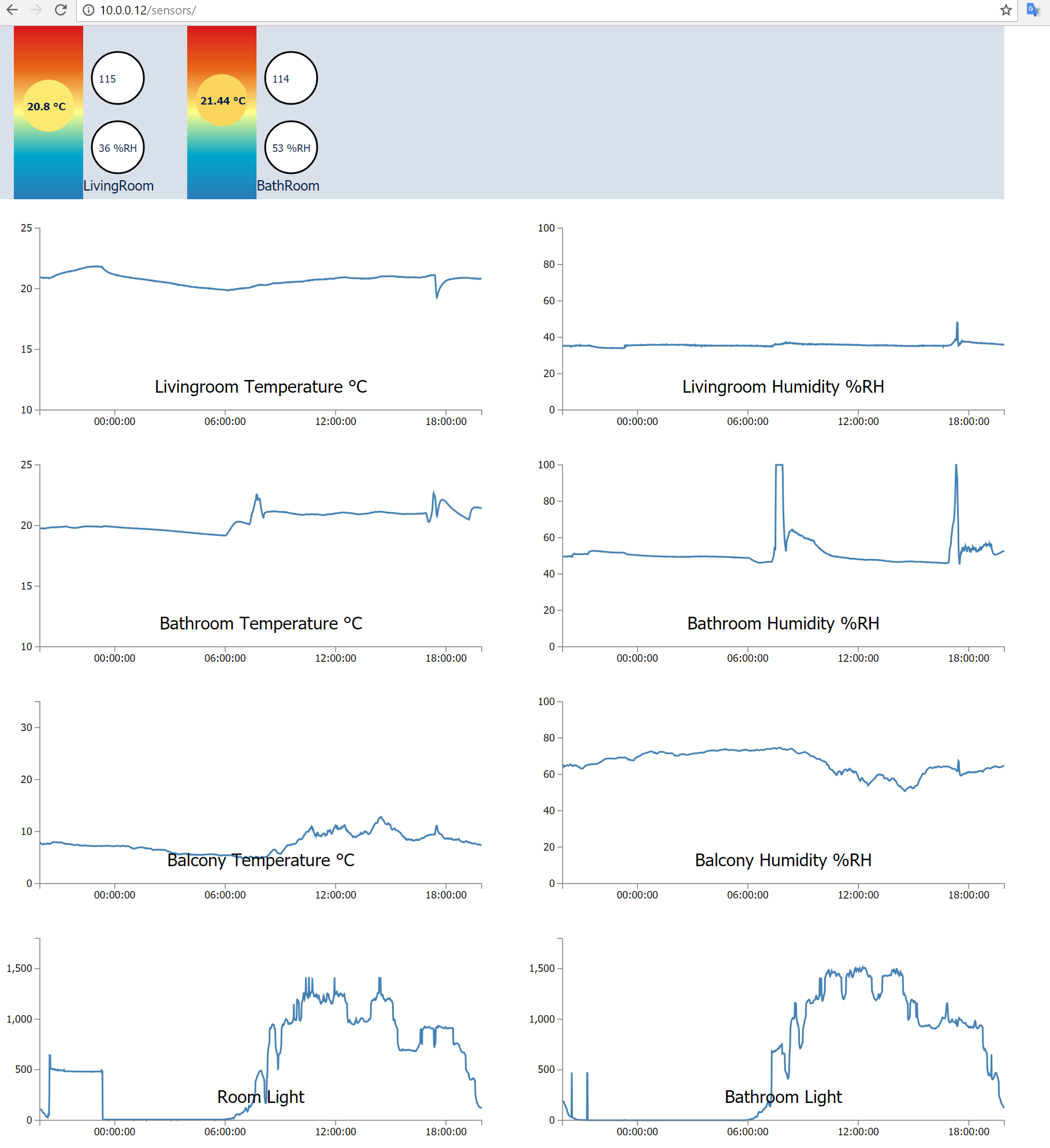
Looking to those curves bring more ideas, for home automation yes we can feel here that it was raining outside, that someone took a shower at around 8h and went to sleep at around eleven the night before (of course entries are more precise down to the second).
![]()
-
Open the bathroom window, Close the bathroom window
04/26/2017 at 17:52 • 0 commentsDemo
- On the down right side of the video is the RGB Led status indicator that turns blue when the bathroom is humid (Humidity = Water = Blue) and green again when it is time to close it not to use much eating energy for example.
- In this video, I closed the door to raise the humidity level, then opened the door and the window to evacuate it.
Installation
- STM8L wireless sensor node with its BME280 as a humidity sensor
- An RF Repeater node that is visible on the down right side of the video which has an WS2812B as an RG led status indicator
- A raspberry pi with an RF dongle as depicted in the Gallery HW + SW design
Software : MQTT Ruler
- The relevant software to fulfill this action in addition to the already installed HW+SW, is simply one small MQTT client, I wrote it in C++ but it could be in python as well, this client is nothing more than a ruler, it subscribes to an MQTT message (humidity level of the bathroom sensor id), and then produces a color depending on the level and send it again through another MQTT channel where the RF dongle is subscribed to send an RF signal to the right node id with the color to set.
void mqtt_c::on_message(const struct mosquitto_message *message) { std::string msg(static_cast<const char*>(message->payload) ); std::string topic(message->topic); if(topic.find("Nodes/") == 0) { std::string Text = topic; //the topic is "Node/6/Humidity" utl::TakeParseTo(Text,'/');//remove first section std::string Id = utl::TakeParseTo(Text,'/');//take the second element int NodeId = std::stoi(Id); float humidity_val = std::stof(msg); publish_humidity_status(NodeId,humidity_val);- This code extracts the node id from the Topic, converts the message payload from text to float and sends them together to the "publish_humidity_status()" function which is testing the node id, applying the rule and publishing the message.
- The function applying the rule which converts the humidity float into a color can be seen below
void from_50_Green_to_Blue(float humidity,unsigned char &red,
									unsigned char &green,
									unsigned char &blue)
{
	red = 0, green = 5, blue = 0;
	if(humidity > 60)//60 -> 100
	{
		red = 0, green = 50, blue = 0;
		float factor = (humidity - 60)/40;//0->1
		float blue_f = 255 * factor;// 0 -> 255
		blue = f2c_sat(blue_f);
		float green_f = 50 - 50 * factor;// 50 -> 0
		green = f2c_sat(green_f);
	}
	else if (humidity > 50)//50 -> 60
	{
		float factor = (humidity - 50)/10;//0 ->1
		green = f2c_sat(5 + factor * 45);//5 -> 50
	}
}
The complete MQTT humidity to color ruler can be found with the rest of the IoT_Frameworks repo here in github.
-
60 RGB LEDs shading with that tiny STM8
04/02/2017 at 10:03 • 0 commentsDemo
Yes, the STM8 less than $1 board can do it
- shading colors of 60 LEDs by addressing every of them with the full 24 bits resolution.
Firmware
- The WS2812B bitbanging was detailed on the Hello Mesh Log
- The 60 x 3 BYTEs info for RGB of every LED are first updated in the STM8 memory, then sent out.
Shading colors
What might look sophisticated for an LED application is a basic operation for a graphics application background
//inputs: the leds section to use defined by which led to start with and which one to end before //inputs: The color of the first led to use and the color of the last led to use //action: updates the leds memory with the first and last led colors and all intermediate leds are interpolated //comment: This function does not send the led data bits on the bus, so that multiple operations can // be applied before sending the whole result together with SendLedsArray(); void rgb_Shade(BYTE LedStart, BYTE LedEnd, RGBColor_t ColorStart, RGBColor_t ColorEnd) { int nbLeds = LedEnd - LedStart; BYTE LedId = LedStart; for(int iCount=0;iCount<nbLeds;iCount++)//0-10 { RGBColor_t Ci = rgb_ColorScale(iCount,nbLeds,ColorStart,ColorEnd); rgb_SetColors(LedId,Ci); LedId++; } }- The rgb_Shade() function interpolates a range of LED colors
//input : two colors, and ratio integers //output : the interpolaetd color //Sets the interpolated color between Colors Start and End, to the ratio of iCount/nbCount RGBColor_t rgb_ColorScale(int iCount,int nbCount,RGBColor_t ColorStart,RGBColor_t ColorEnd) { RGBColor_t resColor; int Red = (ColorEnd.R - ColorStart.R);//255 Red = Red * iCount;//0 - 2550 Red = ColorStart.R + (Red / (nbCount - 1));//0 - 255 resColor.R = Red; int Green = (ColorEnd.G - ColorStart.G);//255 Green = Green * iCount;//0 - 2550 Green = ColorStart.G + (Green / (nbCount - 1));//0 - 255 resColor.G = Green; int Blue = (ColorEnd.B - ColorStart.B);//255 Blue = Blue * iCount;//0 - 2550 Blue = ColorStart.B + (Blue / (nbCount - 1));//0 - 255 resColor.B = Blue; return resColor; }- The rgb_ColorScale() interpolates one color to assign to every intermediate LED, which is interpolated between the start and the end color
Animation
- Although we address 60 Leds here, every with a different color, the information needed is parametric so very small and packed in few bytes to be sent in a small rf packet.
- That could display smart information such as the Traffic conditions on the every day drive through path, or a heat map,...
- The animation in the video has another loop on top, that interpolates the end color from Blue to RED, which is then fed as ColorEnd to the rgb_shade() function
Source code
- Just to mention that the complete project ready to flash on an STM8 with the IAR studio is part of the IoT_Frameworks github, namely in the rgb_led_bar folder
Home Smart Mesh
Mesh of sensors, zigbee, custom RF, BT, wifi, all to MQTT Gateways on Raspberry Pi with database, dashboard and webapps.
 Flood versus Routing