 Next Builder
-
1CAD & 3D Printing
![]()
![]()
![]()
![]()
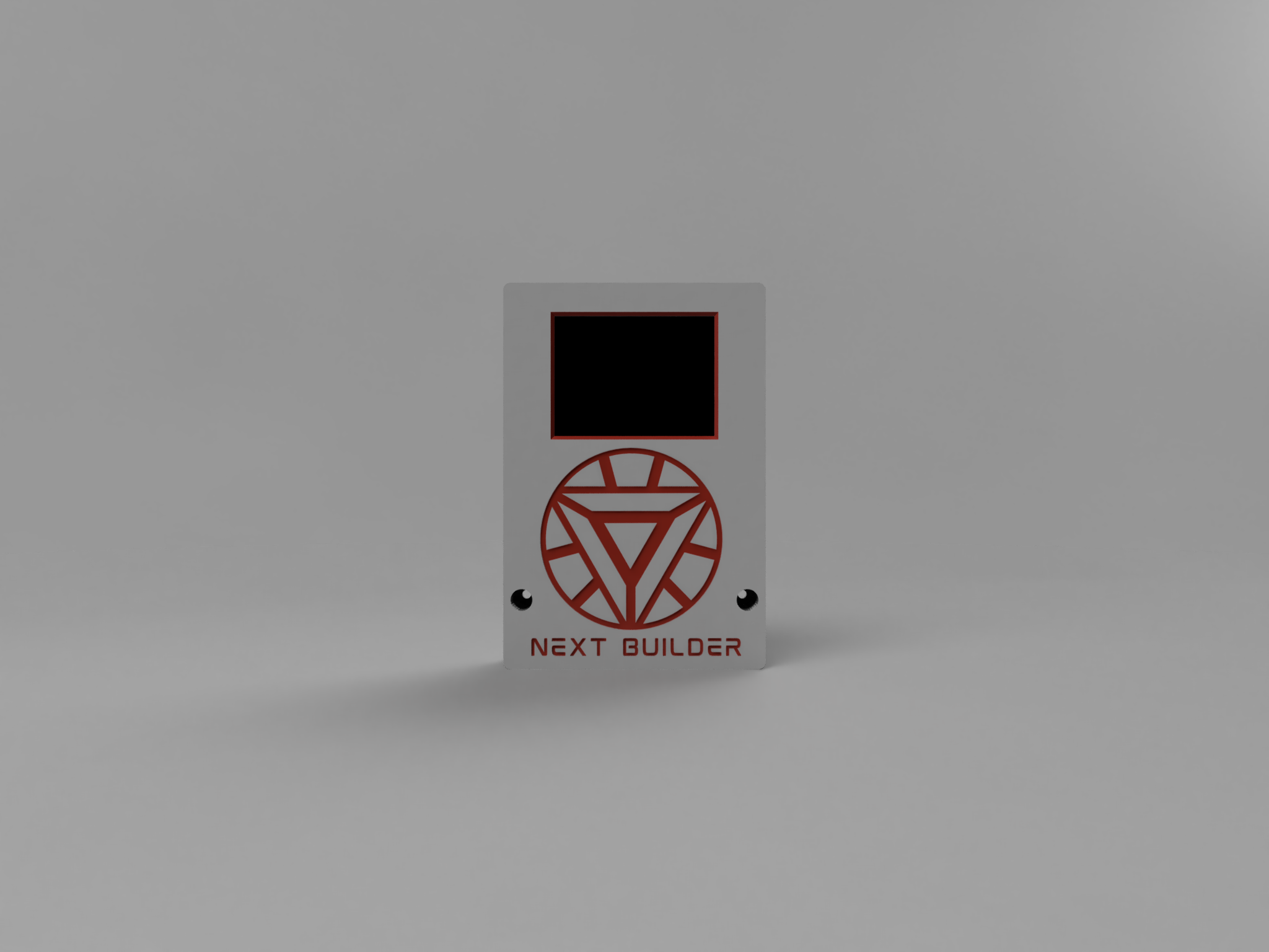
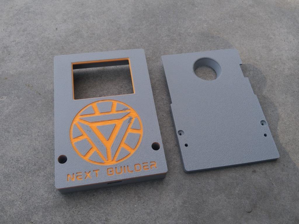
To start this project, I Started designing the CAD using Fusion 360. It’s a simple and compact design that’s easy to print and assemble.
For 3D Printing, You can directly download the required STL files below:
- Main Panel.stl
- Back.stl
For 3D printing, I Recommend PCBWay, a professional 3D printing service known for its high precision, affordable pricing, and wide range of material choices. They support advanced technologies like SLA, SLS, MJF, and FDM, delivering smooth and durable parts that are ideal for both prototypes and final builds.
One of the best things about PCBWay 3D printing is their fast turnaround time and reliable worldwide shipping, making it super convenient for hobbyists, students, and professionals alike. Whether you’re just getting started or working on a serious engineering project, PCBWay is a great choice.
This September, PCBWay is offering TPU (FDM) 3D printing from just $7.96, up to 80% off! TPU is the perfect material for flexible yet durable parts. With PCBWay’s professional-grade 3D printing, high precision, smooth finish, and reliable global shipping, you can bring your flexible ideas to life at the best price. Bigger weight, bigger discount – limited time only, Sept 1–30!
👉 Use the link to get an exclusive discount on your first 3D printing order from PCBWay!
-
2Face Recognition
![]()
![]()
![]()
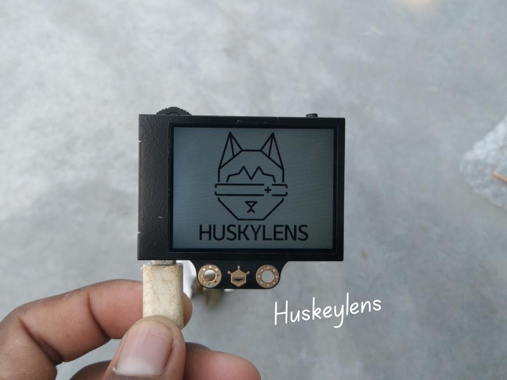
Registering your face on the HuskyLens is very easy. Switch the HuskyLens to Face Recognition mode, then Point the + symbol at a face, short press the learning button to learn the face. If the same face is detected by HuskyLens, a blue frame with words Face: ID1 will be displayed on the screen, which indicates that HuskyLens has learned the face and can recognize it now.You can repeat the process to add multiple faces, each with its own unique ID.
-
3Huskeylens Assembly
![]()
![]()
![]()
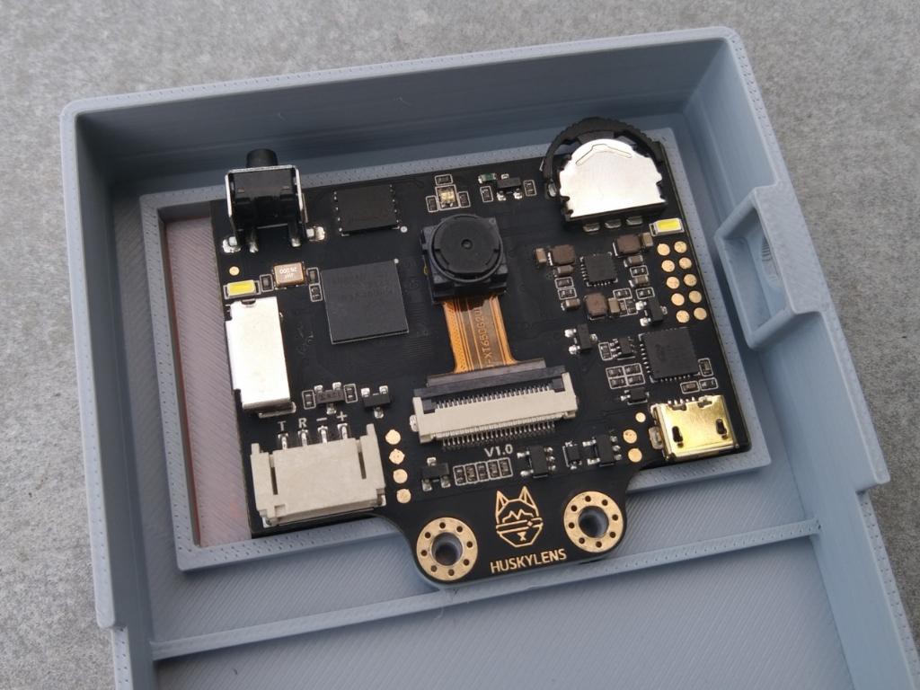
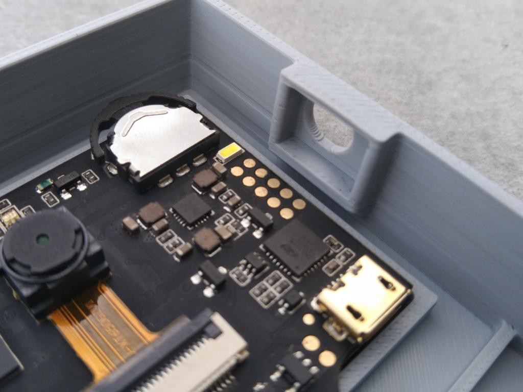
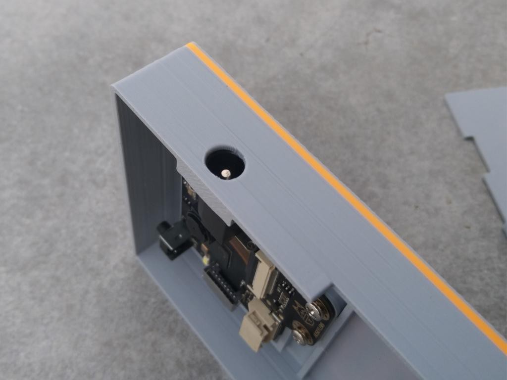
Start by placing the HuskyLens into its dedicated slot inside the enclosure. Make sure it is aligned correctly with the front opening for a clear view. Once positioned, secure it firmly using the two provided screws.
After securing the module, connect the included 4-pin JST connector to the HuskyLens. This connector makes the wiring neat and simple, ensuring a stable and reliable connection.
-
4DC Jack Assembly
![]()
![]()
![]()
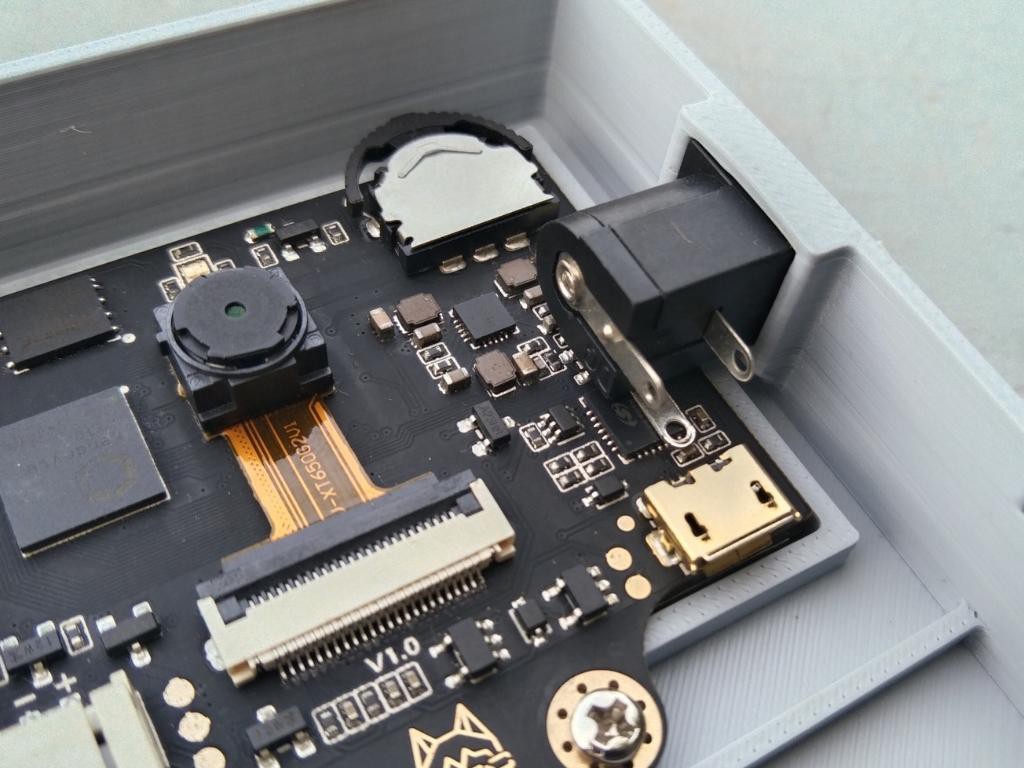
Insert the DC female jack into the dedicated slot in the enclosure. Ensure it is properly aligned so that connecting the male jack from outside for power input will be smooth and convenient. To secure it firmly in place, apply small amount of T-7000 glue (or any strong adhesive of your choice).
-
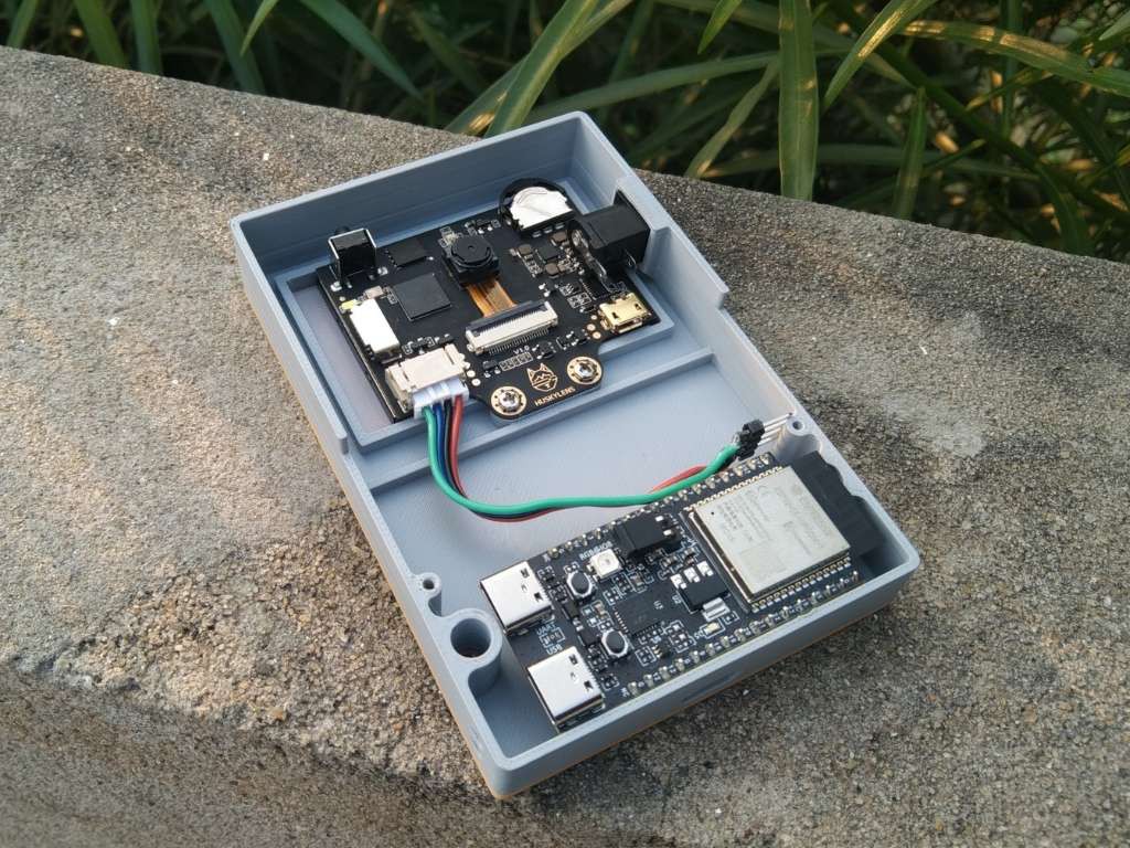
5Microcontroller Assembly
![]()
![]()
Place the microcontroller inside the enclosure at the cutout for the Type-C port. Align it properly so the Type-C connector is accessible from outside for easy programming. Apply a small amount of T-7000 glue to fix it in place. Don’t use too much glue—just enough to hold it securely.
-
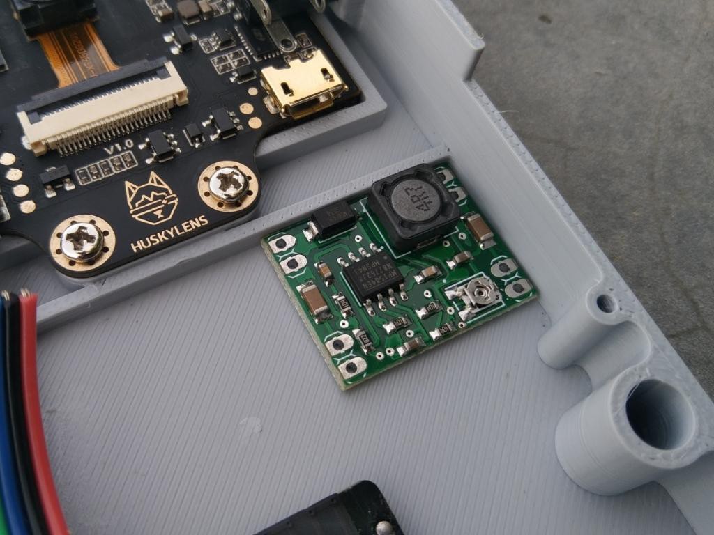
6MP1584 Setup & Assembly
![]()
There isn’t a dedicated slot for the MP1584 buck converter, so you can place it in any free space inside the enclosure. Before fixing it with T7000 glue, first set it up for a stable 5V output. To do this, connect two wires to the input and provide 12V. Then, measure the output voltage and carefully rotate the potentiometer on the buck converter until it reads exactly 5V. Once it is set, secure the module inside the enclosure.
Warning: Be gentle while adjusting the potentiometer. Rotating it too much can cause sudden voltage spikes, which may damage your circuit.
-
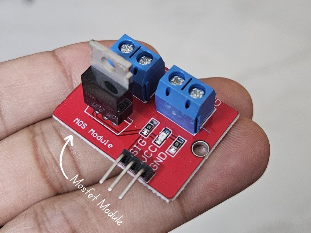
7Mosfet Assembly
![]()
![]()
![]()
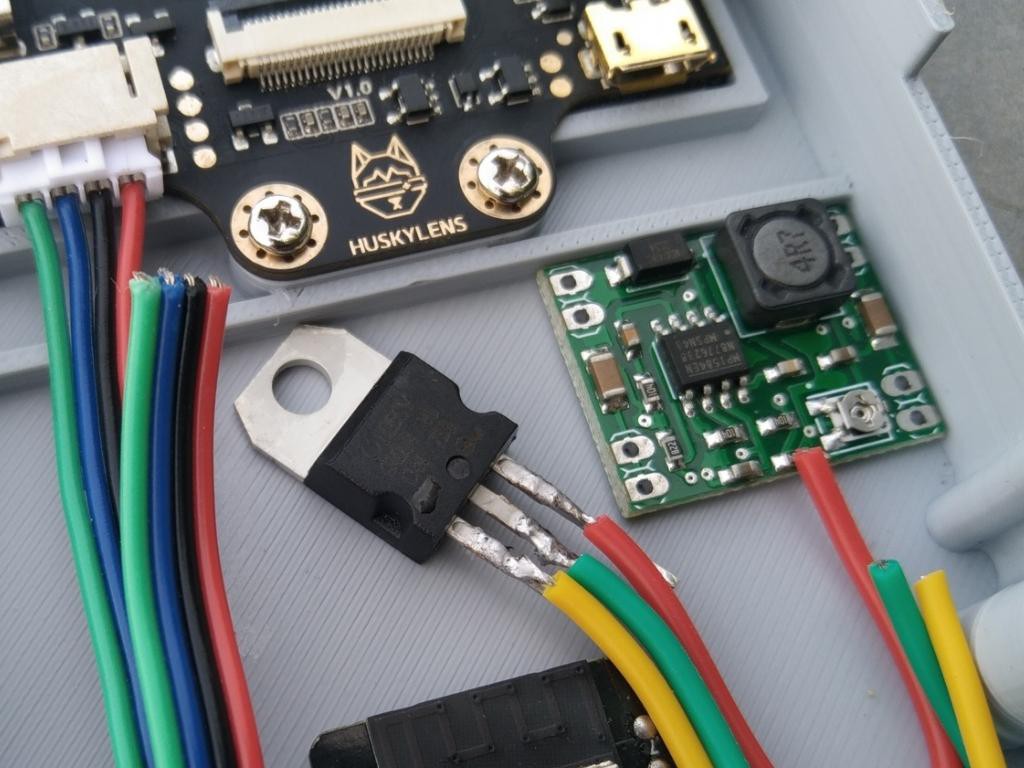
Since the enclosure is designed with a thick wall for a more professional look, the MOSFET module could not be placed directly inside. To solve this, I removed the MOSFET from the module first.
There isn’t a dedicated slot for the MOSFET, so you can place it in any free space inside the enclosure. Once positioned, secure it firmly using T-7000 glue. Make sure the MOSFET is fixed properly and has enough space for air circulation, as it can heat up during use.
-
8Solenoid Lock
![]()
![]()
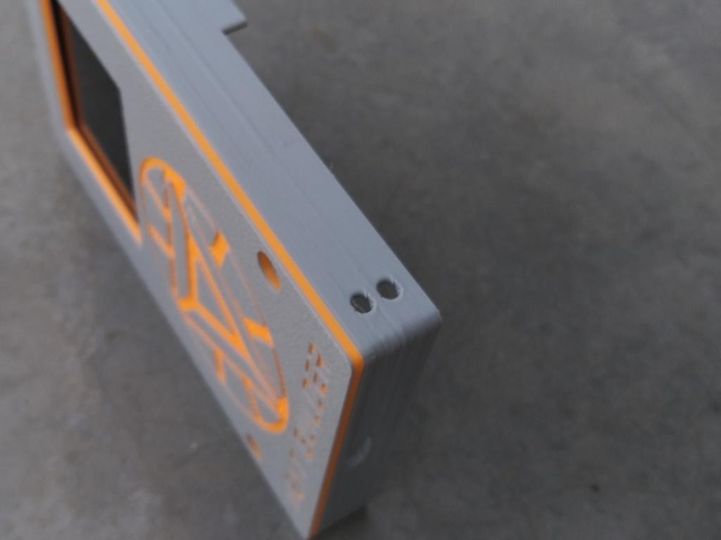
Pass both wires of the solenoid lock through the two small holes provided in the enclosure. These holes are made specifically to allow the wires to pass through easily for proper connection. Ensure the wires are passed gently without pulling too hard to avoid damage.
-
9Connection Diagram
![]()
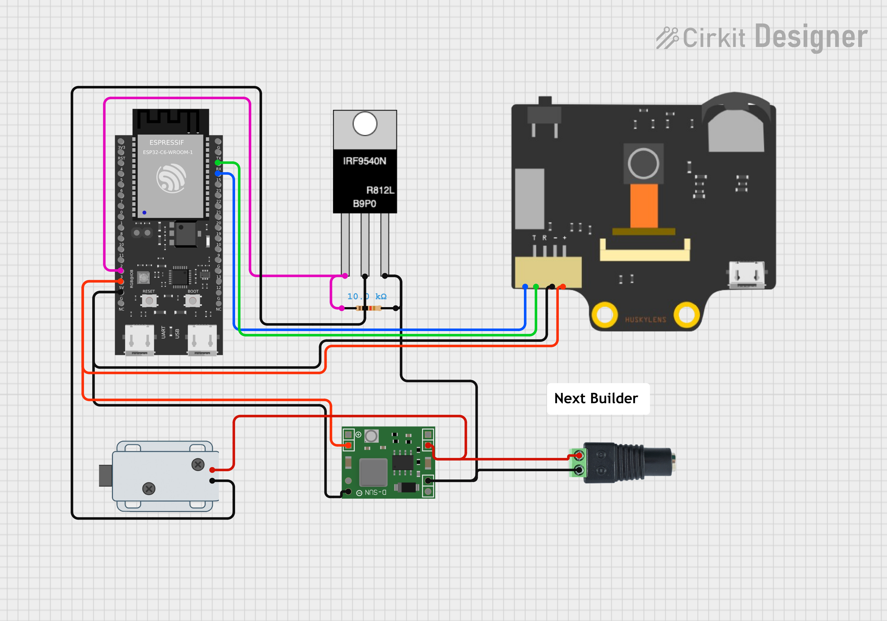
You can follow the circuit diagram above to make all the connections. However, for clarity, I’ve also explained each connection step by step below.
HuskyLens AI Camera
- VCC → 5V pin of ESP32-C6
- GND → GND of ESP32-C6
- TX → RX of ESP32-C6
- RX → TX of ESP32-C6
DFRobot Beetle ESP32-C6
- VIN → 5V output from MP1584 buck converter
- GND → Common GND (shared with HuskyLens, MOSFET, and power supply)
- TX/RX → Connected to HuskyLens
- GPIO pin → Gate of MOSFET (through resistor)
MOSFET (for Solenoid Control)
- Gate → ESP32 GPIO pin
- Source → GND
- Drain → Negative wire of Solenoid Lock
Resistor connected with Gate & Drain Pin
Solenoid Lock
- Positive wire → 12V supply
- Negative wire → MOSFET Drain
Power Supply (12V input via DC Jack)
- Positive → Solenoid Lock positive wire + input of MP1584 buck converter
- Negative → Common GND to MP1584 Buck Converter.
MP1584 Buck Converter
- Input + → 12V supply positive
- Input – → 12V supply negative (GND)
- Output + → ESP32 VIN (5V)
- Output – → ESP32 GND
-
10Final Assembly
![]()
![]()
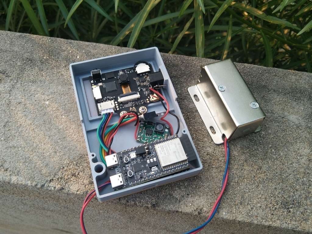
Once all the components are in place, align the cover with the bottom enclosure and ensure the camera opening is clear. Match the orientation properly, then secure the cover using two screws. Do not overtighten the screws, as this may damage the enclosure or misalign the cover.
Face Recognition Door Lock With Smartphone Notific
A smart Face Recognition Door Lock built using the HuskyLens AI Camera and ESP32-C6.


Discussions
Become a Hackaday.io Member
Create an account to leave a comment. Already have an account? Log In.