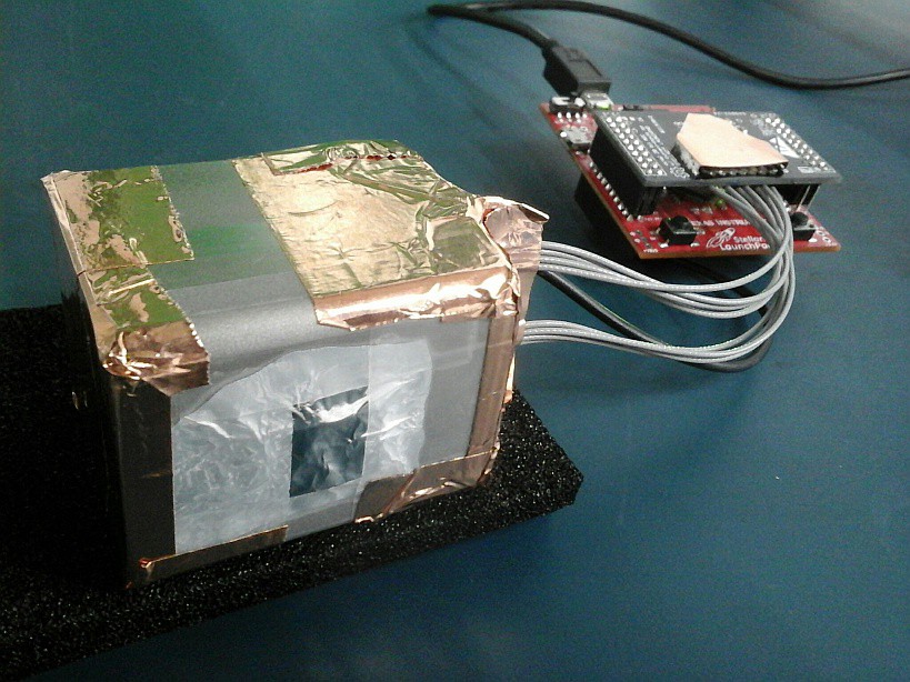
40x40 mm² stainess square tubing with 8mm tapped holes - one for mounting an aluminium cube, the other to pass the "light" through and the PIN diode array PCB glued to the cube. Add a 1.5x3 mm² pinhole made from 2mm thick lead sheet, light seal all openings with copper tape, Al tape over the pinhole. Done. Note: this is not a transmission measurement but a backscattering geometry.
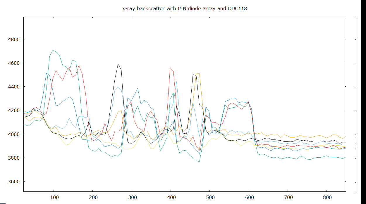
horziontal: time (50ms intervals), vertical: 7 of 8 channels (something went wrong, maybe a connector came off...)

What you see here is the raw 1D image of an 8 pixel x-ray pinhole camera observing a piece of stainless steel illuminated by an x-ray tube ~8cm away as I'm waving it around (duct-taped to a PP tube and held where the dose rate is <2µSv/h).
...And here's just the channels with a bit of smooth kdensity. At approx. sample #610 the x-ray supply is switched off.

It has proven effective to let the analog ground float inside the metal enclosure and connect case GND to the digital ground of the launchpad.
Let me conclude this log entry with a snapshot of the pinhole camera setup. Note this is a different board but I still put that Faraday shield over the exposed input pads. Black cable is chassis GND.

edit: Settings: 18kV, 110µA. Nice.
 helge
helge
Discussions
Become a Hackaday.io Member
Create an account to leave a comment. Already have an account? Log In.