 Craig D
-
Power conversion with a pile of coax
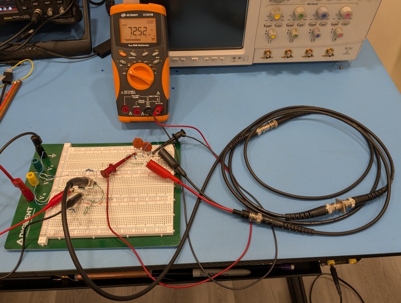
10/17/2025 at 00:08 • 0 commentsWe can also use some regular coax as voltage boosting device. But we'll need an awfully long piece of it for my current frequency limited setup. Here's an example using three 1m RG-58 test cables connected together to form a 3m cable. This length should have a propagation delay of about 15.2ns, based on 0.66 velocity factor. The operating frequency should be about 1/(4*td), or 16.5MHz.
I connected the coax up to the same voltage doubler rectifier, and loaded it with a total of 5k ohms, and powered it up. I adjusted the frequency for maximum voltage, setting on 13MHz - a little lower than expected. The peak DC voltage was 72.5V, as you can see on the DMM, which works out to 1.05W across the load. This was with an input voltage to the driver of 11V. The input current was 0.35A. The input power was 3.85W, so the system is about 27% efficient.
I was going to try cranking the voltage up some more, but noticed the DMM reading slowly drifting downward. If I shut if off for a while, it would recuperate. The culprit appeared to be the poor UCC27524 dual gate driver, with its one remaining channel bearing the burden of driving the coax. It was warming up fast, as it has quite high output resistance - 5 ohms typical when pulling high, and 0.5 ohms typical when pulling low. So I didn't push the voltage farther since I'm not sure I have another working spare part.
![]()
-
Cranking up the power
10/16/2025 at 14:47 • 0 commentsI was curious how much power I could get out of the converter. The rectified output makes it very easy to measure. I just swapped the neon lamps for some 1/4 resistors. This setup has an effective resistance between Vo_Positive and Vo_Negative of 100k.
![]()
I powered it up, tuned the frequency, then cranked the power supply for the driver to 19V. The output voltage rose to 236V. This works out to 0.557W across the net 100k load -- not bad! The power supply meters read 19V and 70mA, for an input power of 1.33W. The efficiency works out to 42%.![]()
-
Adding a rectifier for bipolar HV DC
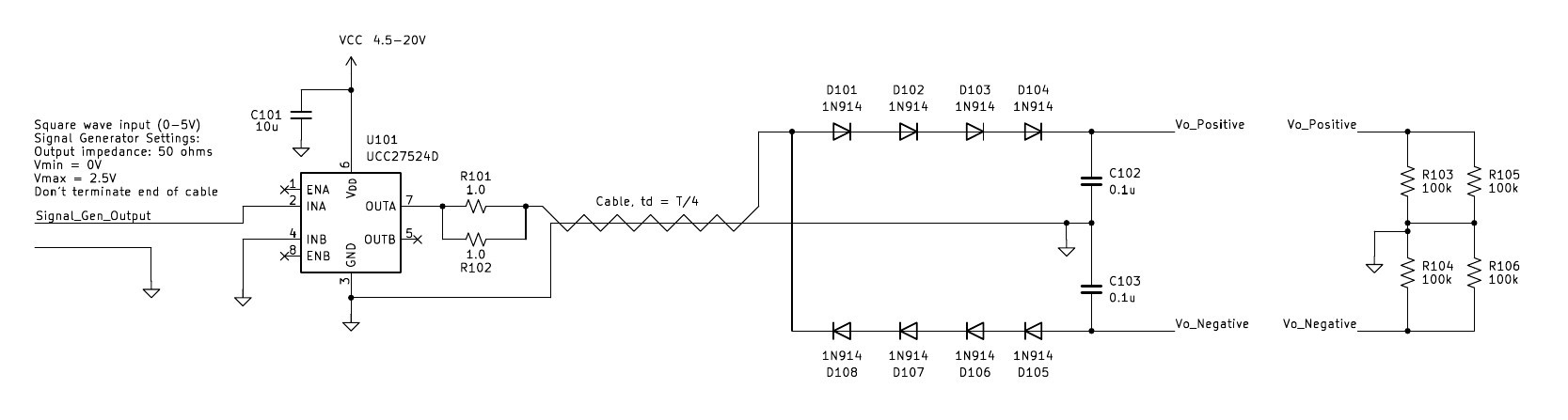
10/16/2025 at 14:37 • 0 commentsWe can make our power converter more practical by rectifying the output. Further, with the output being bipolar, we can easily create a bipolar DC output voltage. One thing to be careful about is capacitive loading from the rectifier diodes, which the circuit can be rather sensitive to. I had a bunch of 1N914 diodes lying around, which have 4pF. This capacitance is a bit high, but can circumvented by stringing several in series. I used a voltage doubler rectifier to create the bipolar DC outputs. The upper string of diodes charges the upper capacitor to when the cable's output is positive, and the lower string charges the lower capacitor when the cable output is negative.
![]()
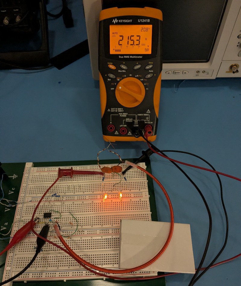
The converter was much less finicky with the rectified output. I was able to easily power two neon lamps with 100k series resistors. The DMM is hooked up to measure the total voltage, from Vo_positive to Vo_negative. The driver (U101)'s power supply was set to 10V. I adjusted the frequency for maximum voltage. The optimal frequency was 10.3MHz. Note that the input ends of the diode strings are "air wired" to the cable's output to avoid adding capacitance from the breadboard.
![]()
-
Building a proof of concept
10/14/2025 at 23:28 • 0 commentsNow that we've got a delay line, it's time to set up the voltage booster! I figured running a neon bulb would be a nice demo, and super simple since it doesn't need an output rectifier. The neon lamp that I used is an A1B type, which should light at 70V.
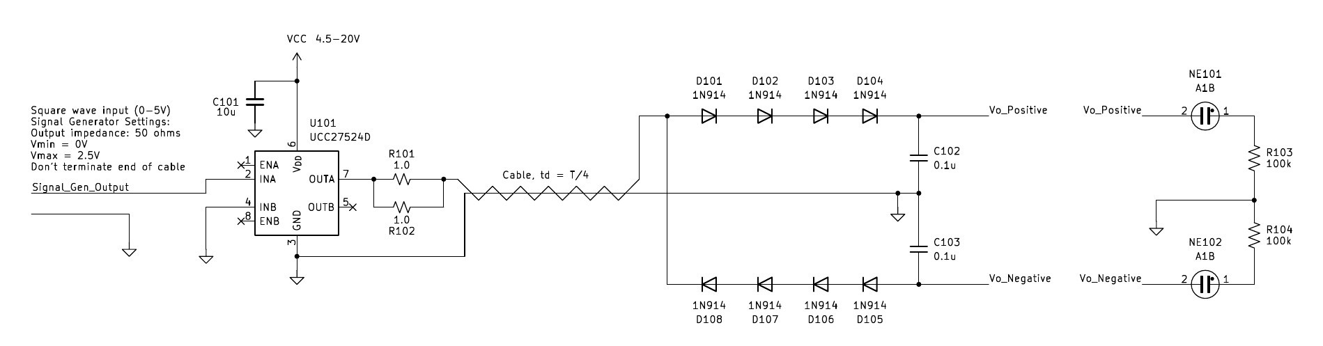
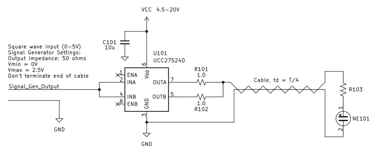
For driving the delay line, a half-bridge or something along those lines would be a good idea. Maybe build with GaN devices for the frequencies at hand? But out of sheer laziness, and disregard for its intended use, I grabbed a high speed gate driver IC (UC27524D) and connected the cable connected to its outputs. While not very robust, it has the benefit of extreme simplicity. Here's the whole schematic.
![]()
According to analysis and simulation, I should be able to run the neon lamp with a large series resistor - 100k. But that didn't work on the bench. However, I was able to get the lamp to light with a smaller or no series resistor. By cranking the supply to 15V, I was able to light two neon lamps in series. By that time, I had burnt up one of the chip's outputs, and just moved both resistors to the lone working output.
![]()
-
Building a cable
10/14/2025 at 14:51 • 0 commentsOne challenge I've run into is that the cable lengths is very large at "lower" frequencies. While I could try things out at GHz level frequencies where this is no longer an issue, it would be nice to experiment at 20MHz or lower to be able to use some parts I have laying around, along with basic test equipment, like a function generator and scope, and standard probes.
For example, let's assume a 10MHz source frequency. The period (T) for 10MHz is 100ns. The cable needs to be T/4, which works out to a cable delay of 25ns. The propagation velocity in a cable would be a bit under the speed of light (c) - let's say 0.7 * c = 2.1E8 m/s. The cable length needed would be about 2.1E8 m/s * 25E-9 s = 7m (23ft)! That's a pretty darn long cable!
What can we do about this? Well, old school CRT oscilloscopes offered some inspiration. They used a delay as an analog memory device to be able to view a bit of signal before the trigger point. Sometimes, they would use a long coil of regular coax. But some used a more elegant solution - a special transmission line with much more delay per unit length. There were different variations, with one conductor wound in a helix to create a longer path length.
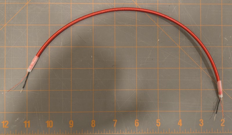
The simplest type of delay I could think of is a center conductor, with magnet wire wound around it in a single layer. That's basically what the cable shown below is. I used a 3mm diameter, 1ft piece of teflon tubing to give it some rigidity. I wound magnet wire along its full length, and fished a piece of hookup wire through the center of the tube to serve as my center conductor.
![]() The cable's characteristic impedance worked out to about 1k ohms, which is actually a good value for generating high voltages at low power. I arrived at this value by measuring the cable's total capacitance with an LCR meter, then shorting one end and measuring the total inductance. They came out to 23pF and 23.8uH, then applied Zo= sqrt(LC).
The cable's characteristic impedance worked out to about 1k ohms, which is actually a good value for generating high voltages at low power. I arrived at this value by measuring the cable's total capacitance with an LCR meter, then shorting one end and measuring the total inductance. They came out to 23pF and 23.8uH, then applied Zo= sqrt(LC).
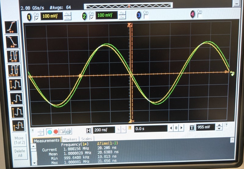
The delay is easy enough to measure with a scope. I terminated the output with 1k, and used a 1k termination on the input, then applied a sine wave. With the termination resistances being pretty high, I had to be careful to avoid probe capacitive loading effects. Thus I measured at 1MHz where the probe's ~14pF capacitive impedance is more than ten times the termination resistance. I ensured the probe delays were well matched, and measured the delay with the scope. Channel 1 (yellow) is the input, and channel 2 (green) is the output, which is slightly delayed as expected. The delay measured about 20.3ns.![]() This is pretty good! A 1ft section of coax has a delay of about 1.3ns of delay, so this little section replaces 15ft of coax. The T/4 source frequency needed would be about 12.5MHz, which isn't too bad.
This is pretty good! A 1ft section of coax has a delay of about 1.3ns of delay, so this little section replaces 15ft of coax. The T/4 source frequency needed would be about 12.5MHz, which isn't too bad.
Boosting voltage with a cable
This project re-purposes a cable as a voltage boosting device


 The cable's characteristic impedance worked out to about 1k ohms, which is actually a good value for generating high voltages at low power. I arrived at this value by measuring the cable's total capacitance with an LCR meter, then shorting one end and measuring the total inductance. They came out to 23pF and 23.8uH, then applied Zo= sqrt(LC).
 This is pretty good! A 1ft section of coax has a delay of about 1.3ns of delay, so this little section replaces 15ft of coax. The T/4 source frequency needed would be about 12.5MHz, which isn't too bad.