Arnov Sharma
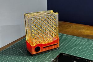
To enhance usability, we added a built-in light source that illuminates the soldering area, which is a huge help during precision tasks.
Both the fan and the light are controlled via individual push buttons, each offering a four-step dimming cycle:
• The first press activates at 50% power
• The second press boosts to 75% power
• The third press reaches full 100% power
• The fourth press turns the output off
The entire system runs on an external 12V power supply, connected through a DC barrel jack mounted on the rear of the unit. For the exhaust, we’re using a 12V 0.18A PC fan salvaged from an old computer. We’ve also included a DIY smoke filter that’s easy to swap out, keeping the air clean while you work.
This article walks you through the full build, from concept to final assembly, so let’s dive in and start building!
Materials Required
These were the components required during the build.
- Custom PCBs (Provided by PCBWAY)
- Raspberry Pi PICO 2
- AO4406 N Channel Mosfet IC SOIC8 Package
- 10K Resistors
- 8205S Mosfet SOT23-6 Package
- AMS1117 3.3V
- 10 uF 1206 Package Capacitor
- 1 uF 1206 Package Capacitor
- M7 Diode SMA
- 12V PC FAN
- Barrel DC Jack
- 4x4 Tactile Push Buttons
- 2835 Warm White 3.3V LED
- 3-Ohm 1206 Package Resistor
- Connecting wires
- 3D-printed parts
- M2 Screws
DESIGN
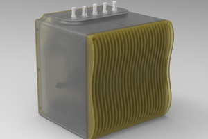
We began the main design of this project by importing a 3D model of a DC fan into Fusion 360. From there, we built a cuboid-shaped enclosure around it. One half of the enclosure houses the fan, while the other half contains the light source, two push buttons, and the Pico Driver circuit.
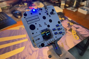
The second half features a switch PCB with two 4x4 tactile push buttons, each topped with a custom switch actuator. We also added a circular LED PCB fitted with four warm white LEDs to serve as the light source. To soften and spread the light, a diffuser was placed over the LED PCB.
To control the entire setup, we designed a long Pico Driver PCB that includes the Raspberry Pi Pico and supporting components. A rear lid was added to the enclosure, which holds a DC barrel jack for powering the system via an external 12V supply.
Above the fan, we created a circular opening in the enclosure and designed a custom grill that pressure-fits into place. This grill allows the fan to draw in smoke from the front. On the rear lid, we added another circular section with grills and a top-side opening. This area is intended to hold smoke-absorbing material, allowing the fan to pull air from the front and pass it through the filter section at the back.
Finally, we designed a base stand with a holder that securely attaches the upper body of the fume extractor to the stand. For the enclosure body and lid, we used transparent PLA. The stand and holder were printed in white PLA, while the switch actuators, front fan grill, and grill cover were printed in orange PLA to create a clean, dual-tone aesthetic.
CIRCUIT DESIGN
The circuit schematic is divided into three main sections: the Pico setup, the AMS1117 voltage regulator, and the MOSFET switch configuration.
At the heart of the project is the Raspberry Pi Pico, which serves as the main microcontroller. To power it from a 12V source, we’ve added an AMS1117 voltage regulator circuit that steps down the voltage to 3.3V, suitable for the Pico’s operation.
To control the DC fan and LED, we use MOSFETs configured as electronic switches. In this setup, the load’s positive terminal is connected to VCC, while the negative terminal is connected to the MOSFET’s drain. When a control signal is applied to the gate, the MOSFET conducts, completing the circuit and powering the load. This allows the Pico to switch high-current devices like fans and LEDs using low-voltage GPIO signals.
We used an AO4406 MOSFET to drive the DC fan and an 8205S MOSFET for the LED. The LED PCB consists of four SMD LEDs connected in series along with a current-limiting resistor.
Both the driver and LED PCBs were designed by tracing the board outlines from the 3D model, ensuring...
Read more »