 Arnov Sharma
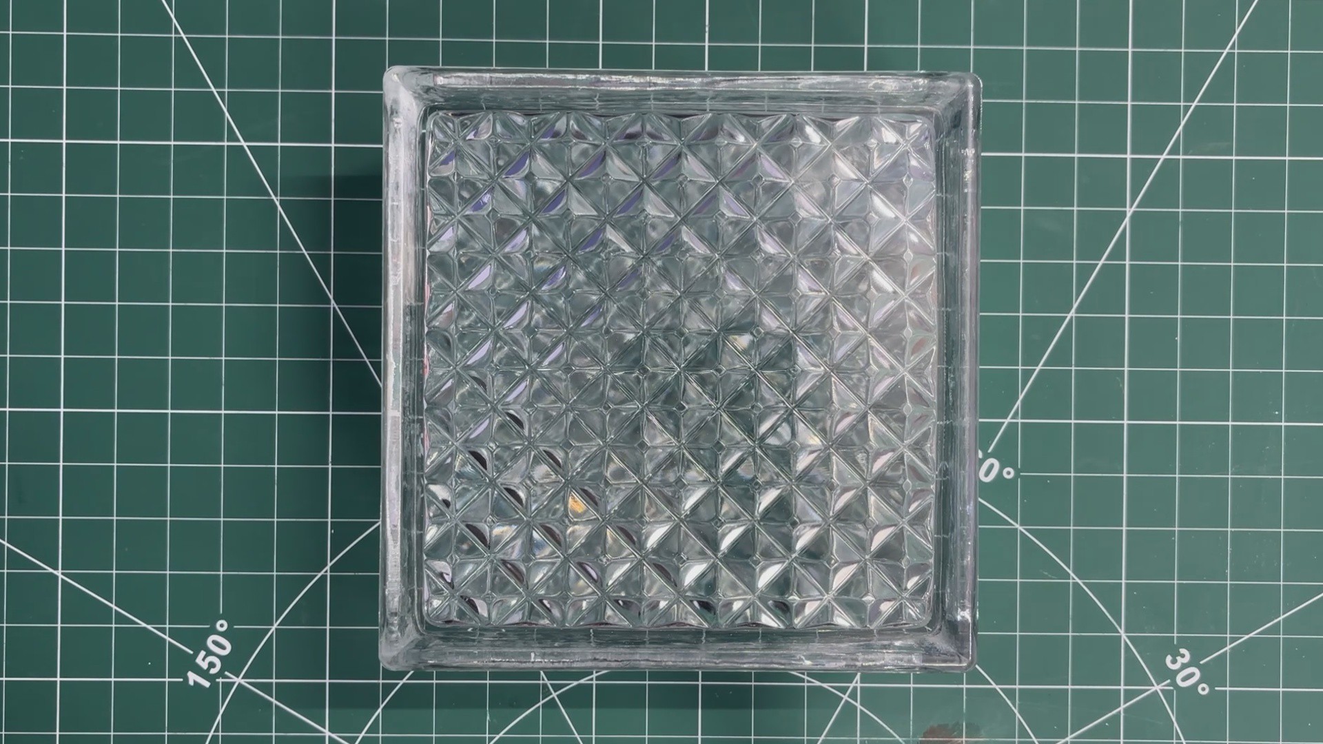
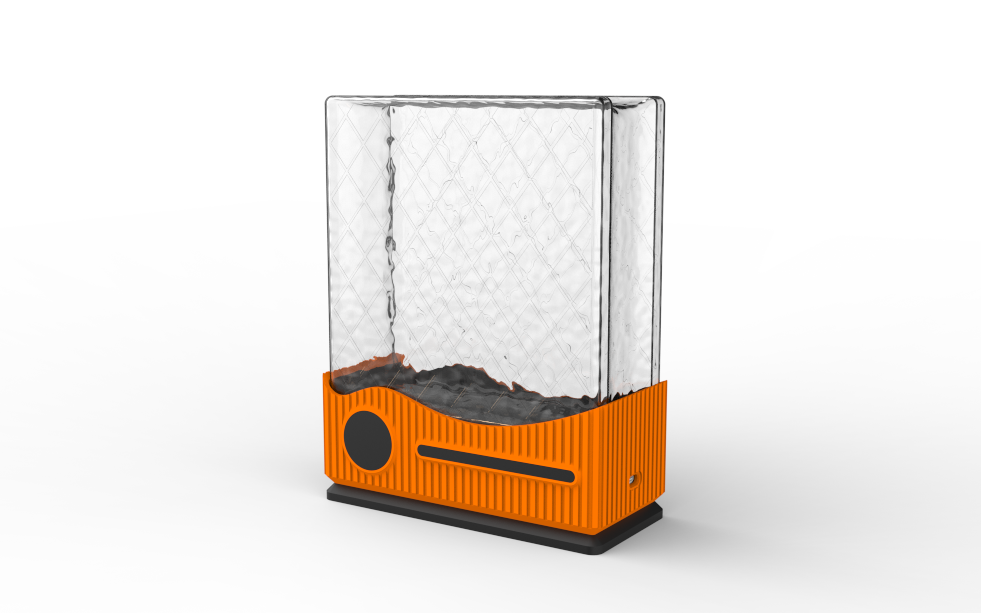
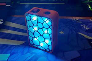
This was the star of our project, a glass brick, which is a hollow or solid block made of two pieces of glass that are fused together.
Because the inside is sealed, it diffuses light beautifully while still remaining strong and durable. Glass bricks are known for their ability to let light pass through while still maintaining privacy, thanks to their frosted or patterned surfaces. Because of this, they are commonly used in partitions, windows, shower areas, and many other architectural applications.
This glass brick was actually a leftover from a renovation project in my home. Since it was an extra piece, I kept it aside—and after seeing glass brick lamps on Pinterest several times, I thought, why not make my own version? That simple idea is what started the entire project.
DESIGN
For the design process of this project, we began by creating a 3D model of the glass brick.
Once that was in place, we imported the remaining components into the design that included the lithium cell, the Medic Mini mainboard, and the RGB LED PCB. We arranged and rearranged these components in different configurations until we found a layout that balanced both functionality and space efficiency.
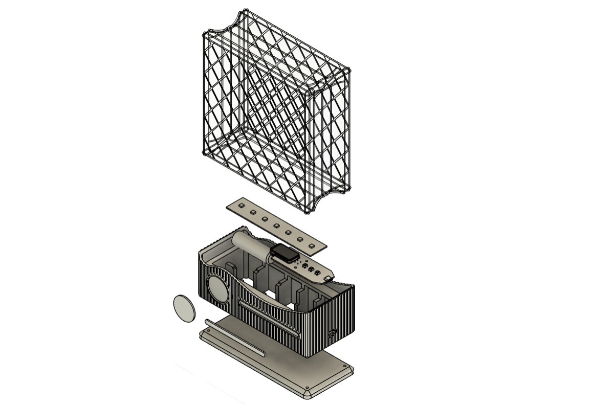
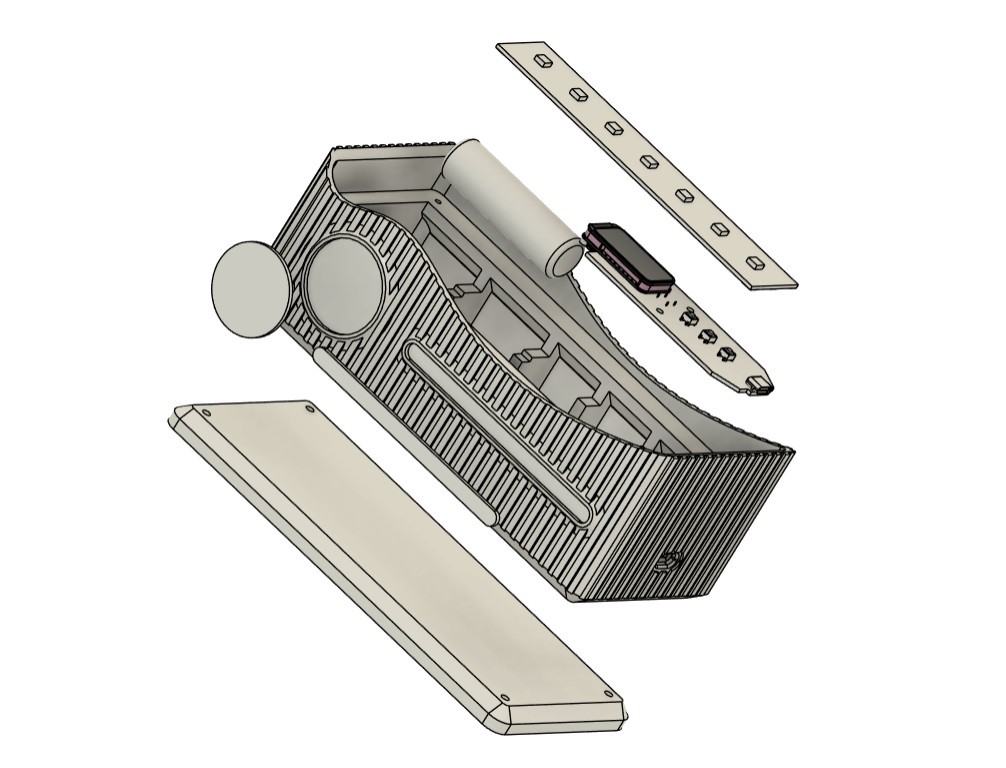
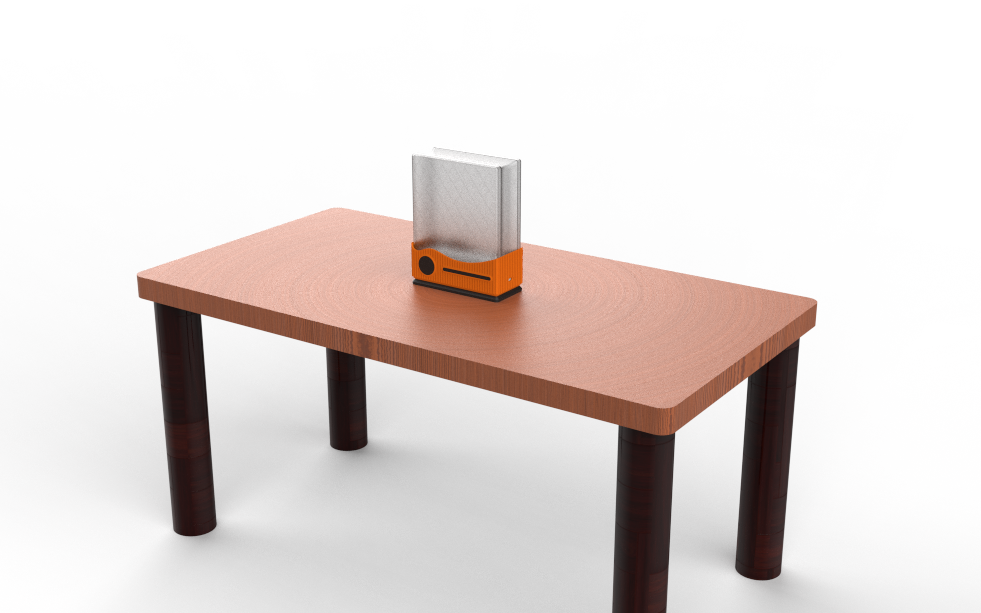
After finalizing the internal arrangement, we designed an enclosure around the components.
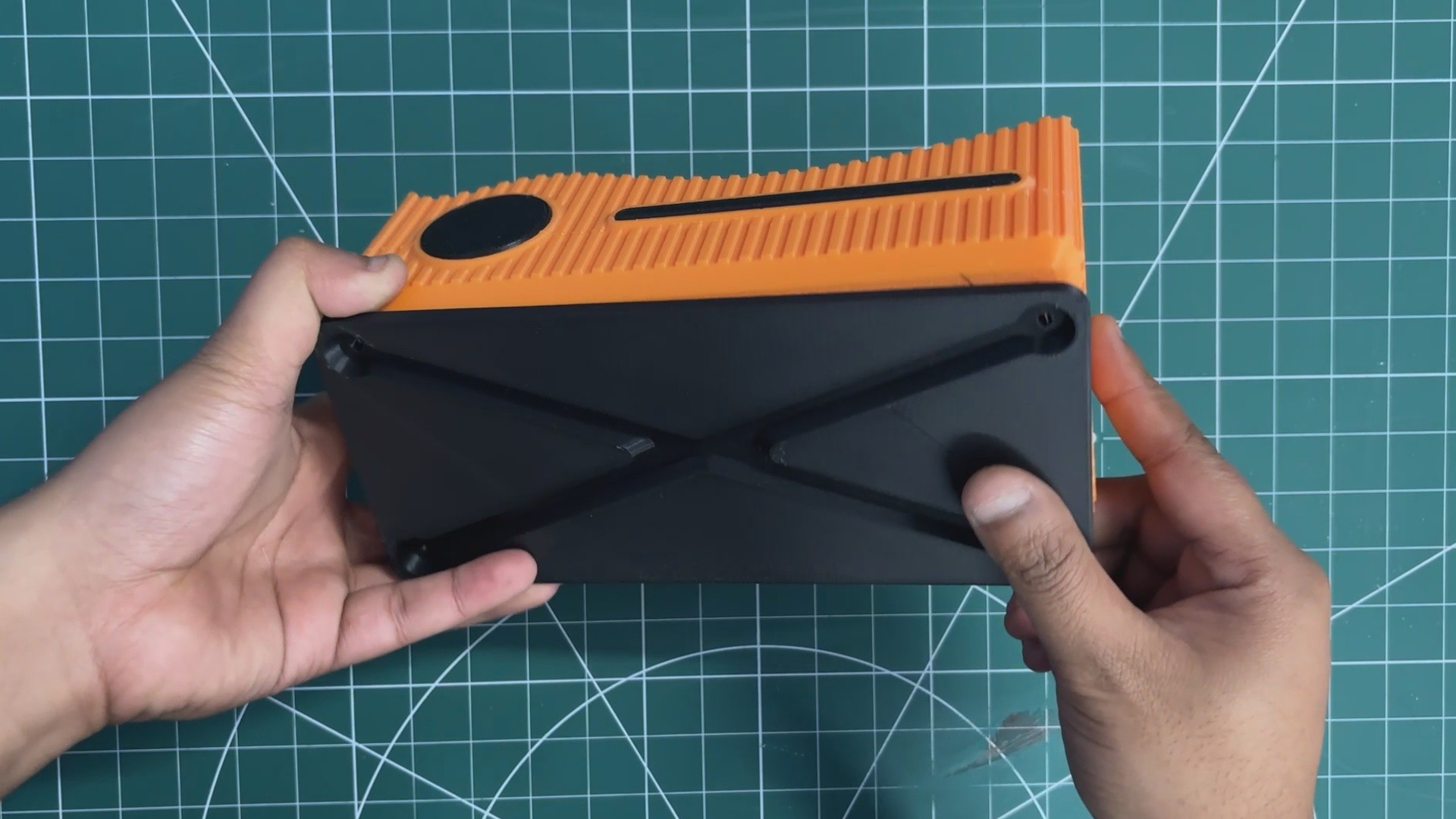
Our enclosure is essentially a box-like housing that securely holds the glass brick at the top. Directly beneath the brick sits the RGB LED PCB, which illuminates the glass from below and makes the entire block glow. Below the LED PCB, we positioned the lithium cell and the Medic Mini board. Since the Medic Mini’s charging port needs to remain accessible, we incorporated a side slot into the enclosure for easy access.
On the front, we added two extra parts purely for aesthetics—these “accent parts” create a clean two-tone effect and are pressure-fitted into place. Finally, we designed a separate base piece that attaches from the bottom and locks onto the main enclosure, which we refer to as the main body.
3D FILES
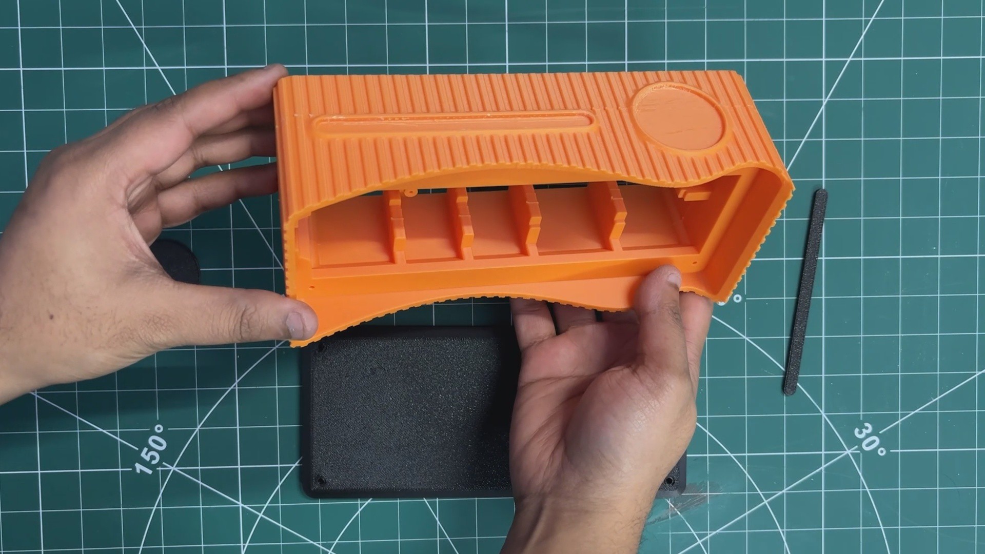
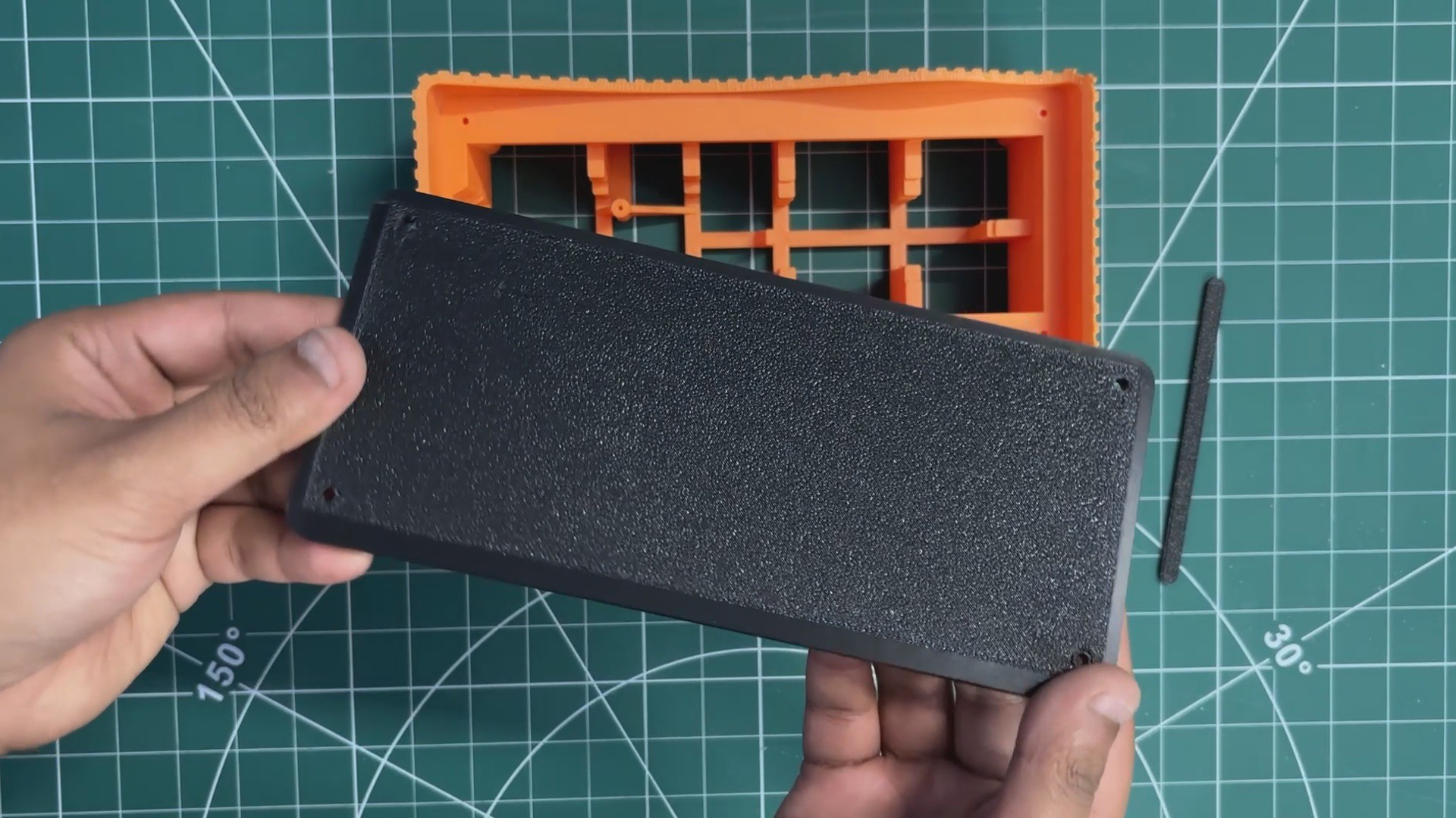
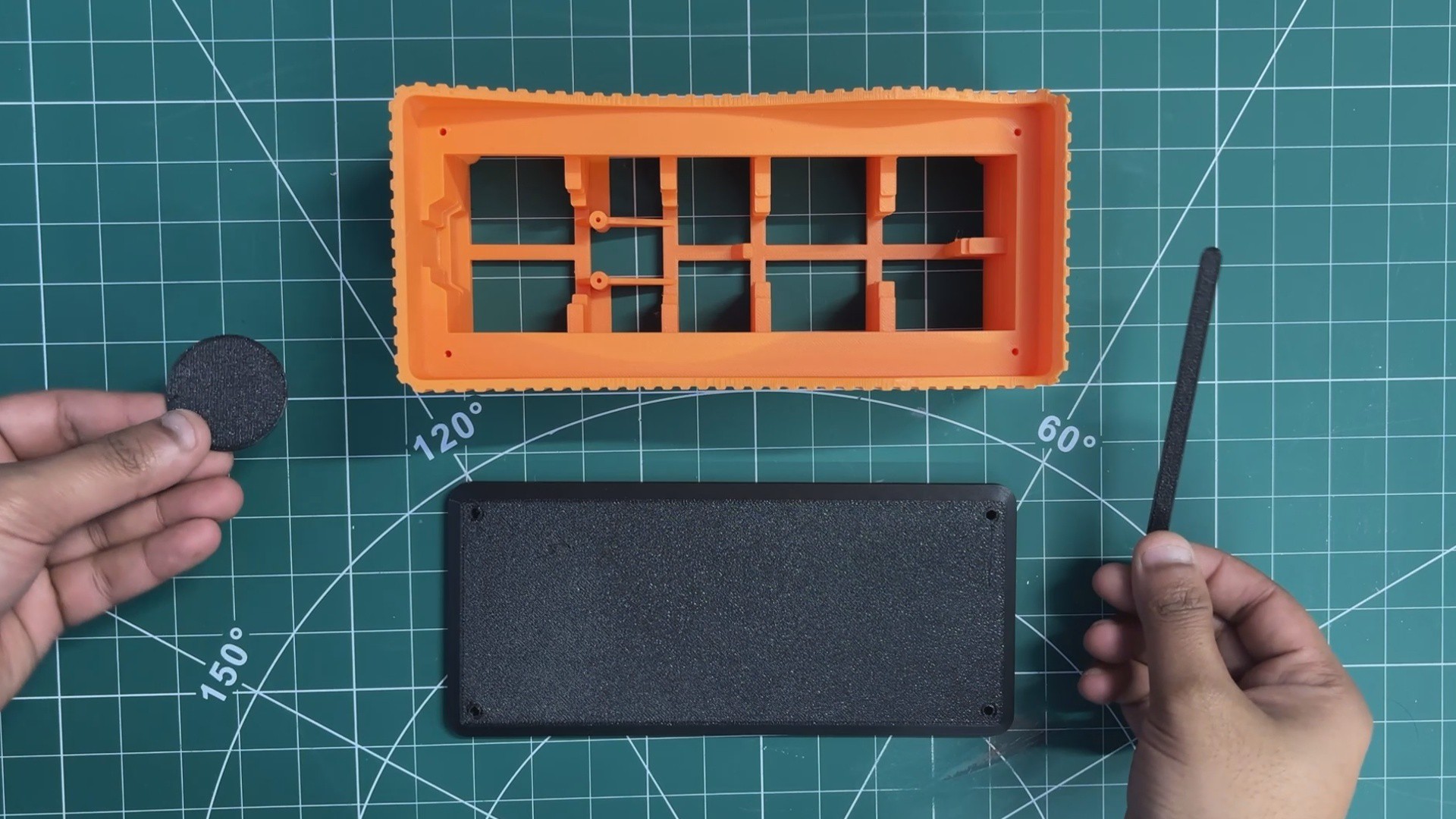
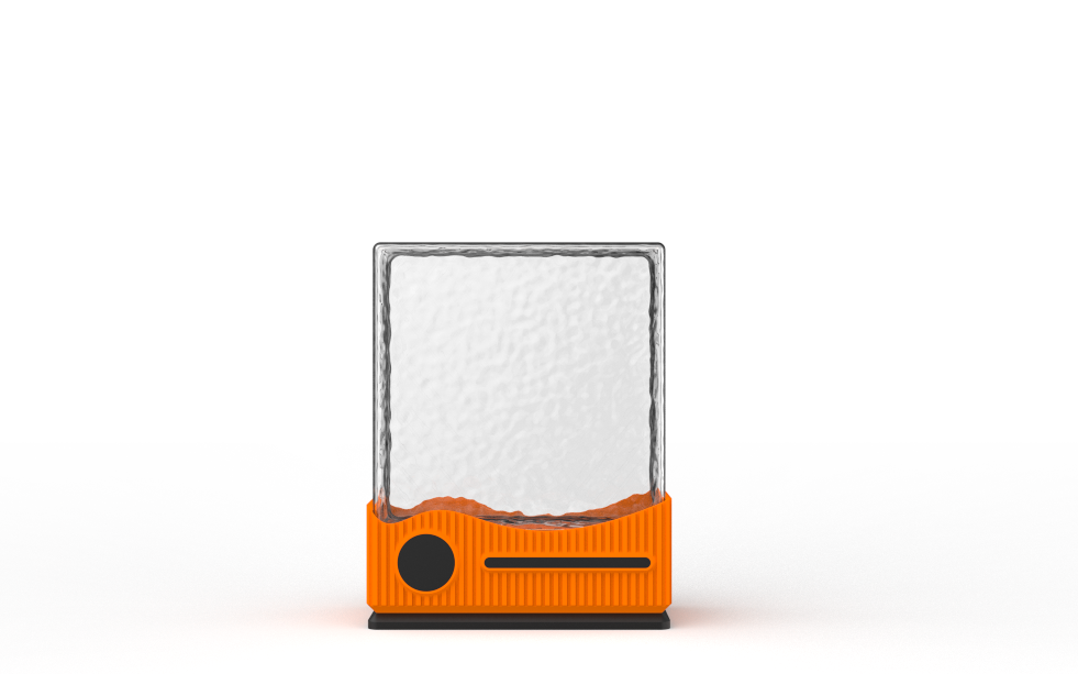
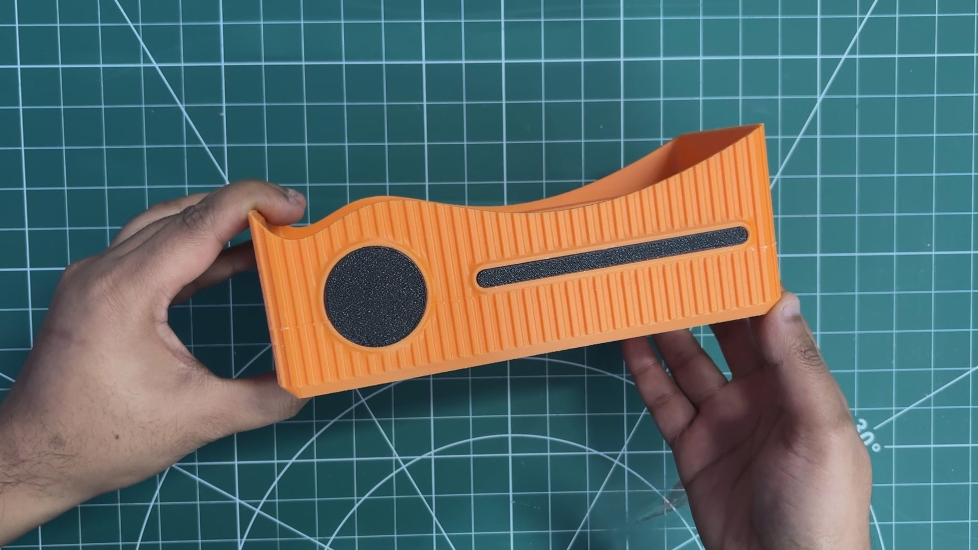
After finalizing the design, we exported three primary parts: the main body that houses the glass block, the base that supports the entire structure, and two accent pieces designed to enhance the overall aesthetic. These accent parts are mounted on the front side of the main body to add visual detail.
All components were exported as mesh files and then 3D printed on our Anycubic K10 printer. The main body was printed using orange PLA, while black PLA was used for the base and accent pieces to create a subtle contrast. We used Hyper PLA with a 0.4 mm nozzle, set the infill to 30%, and printed all parts without requiring any supports.
ELECTRONICS
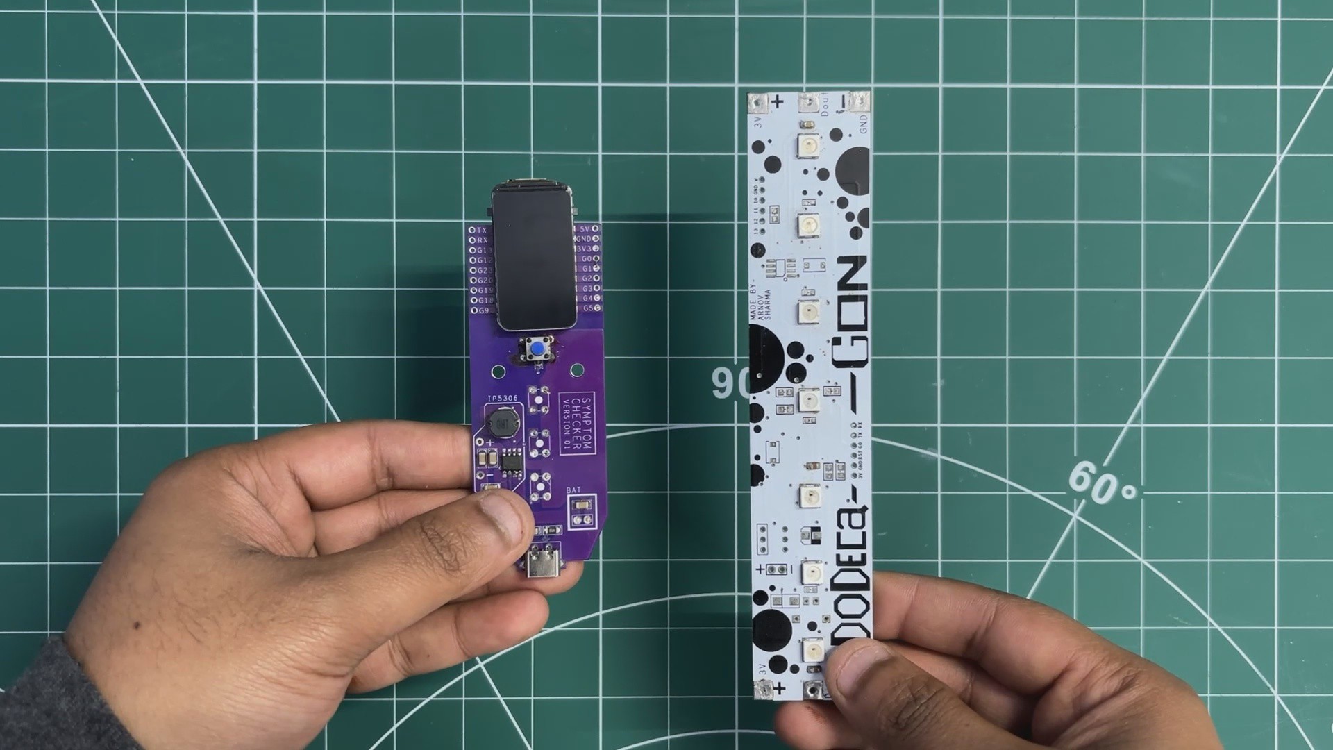
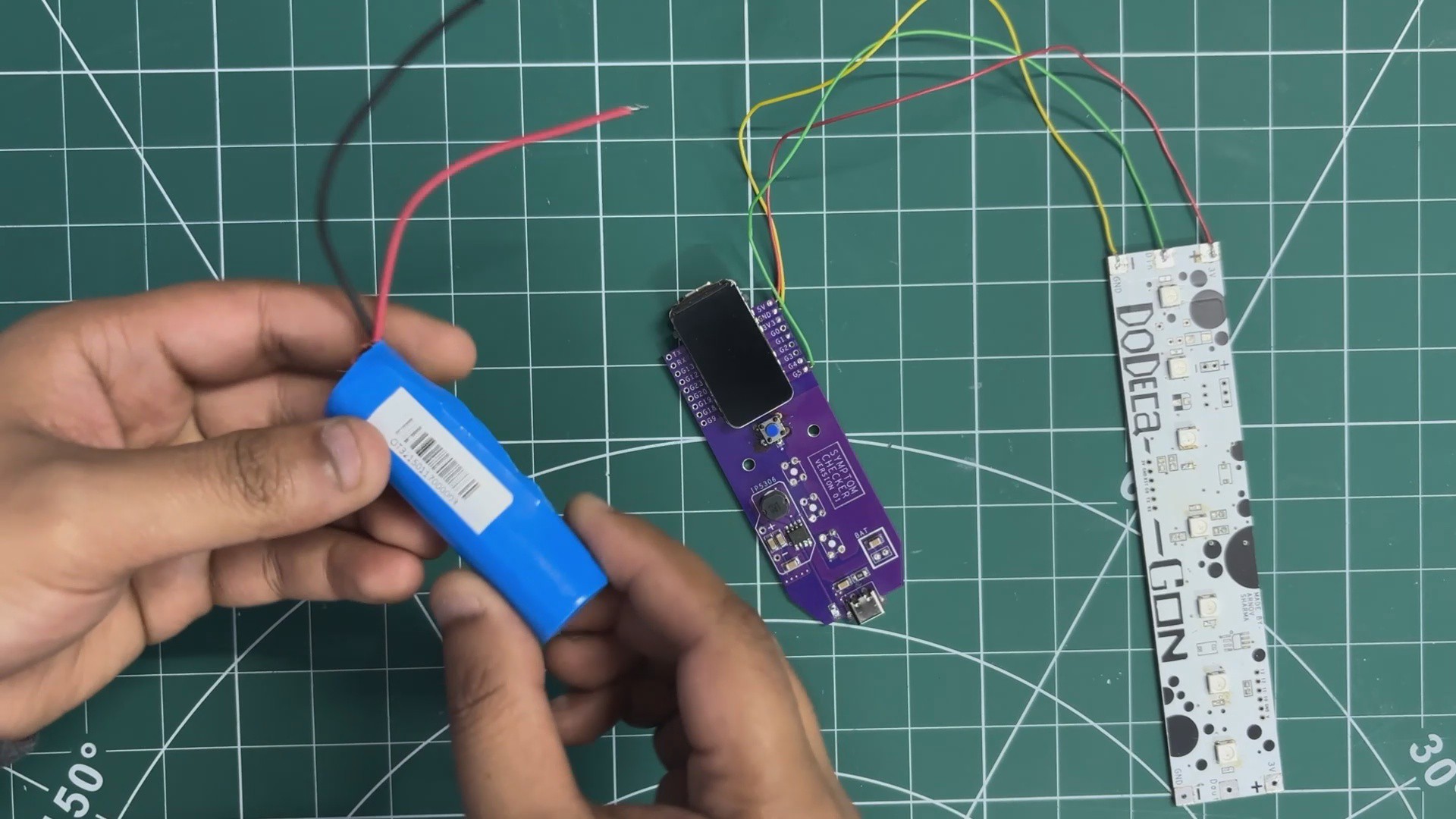
For the electronics, we reused PCBs from two of our previously built projects: the Medic Mini mainboard and the Dodecagon RGB LED PCB.
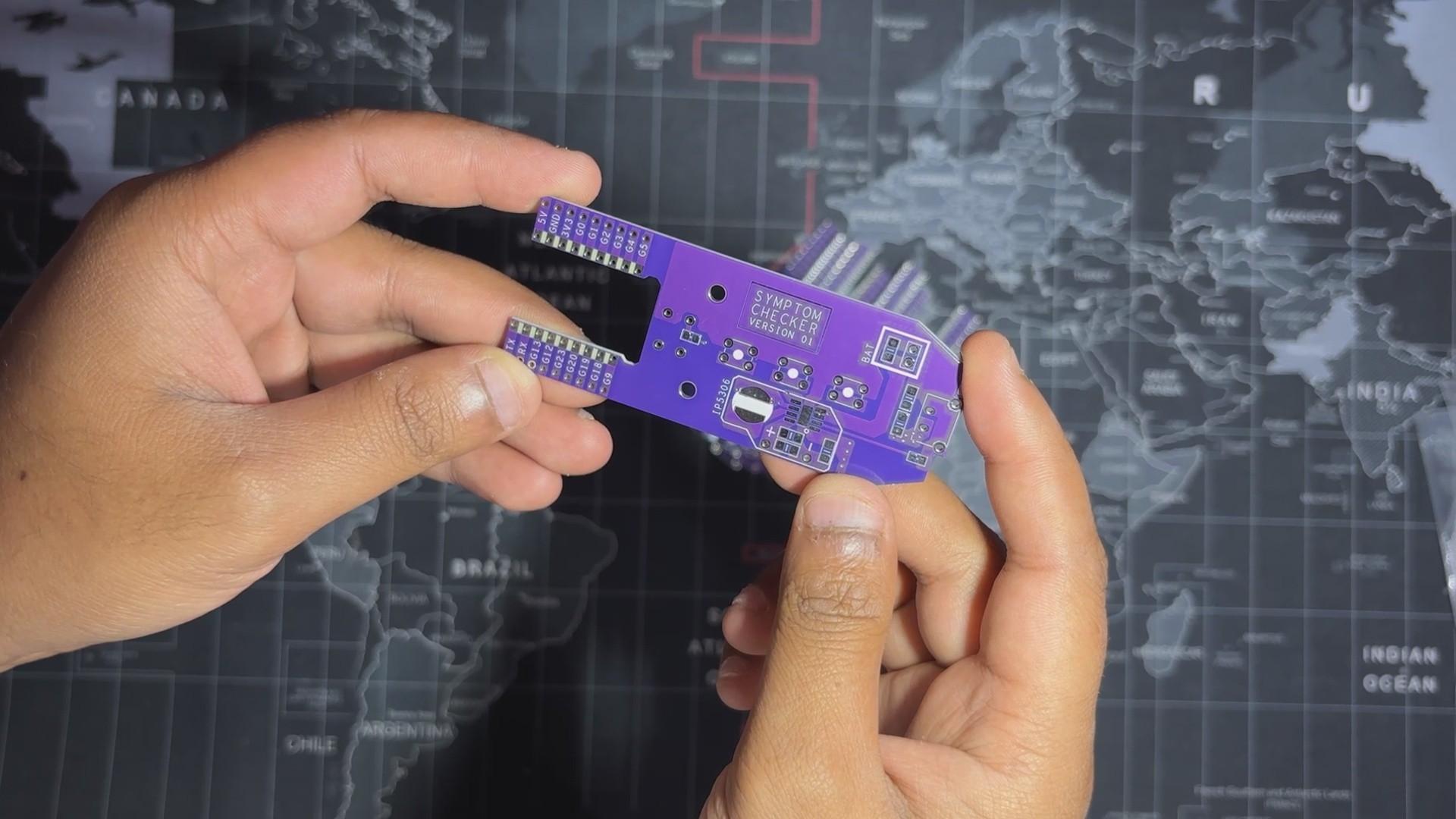
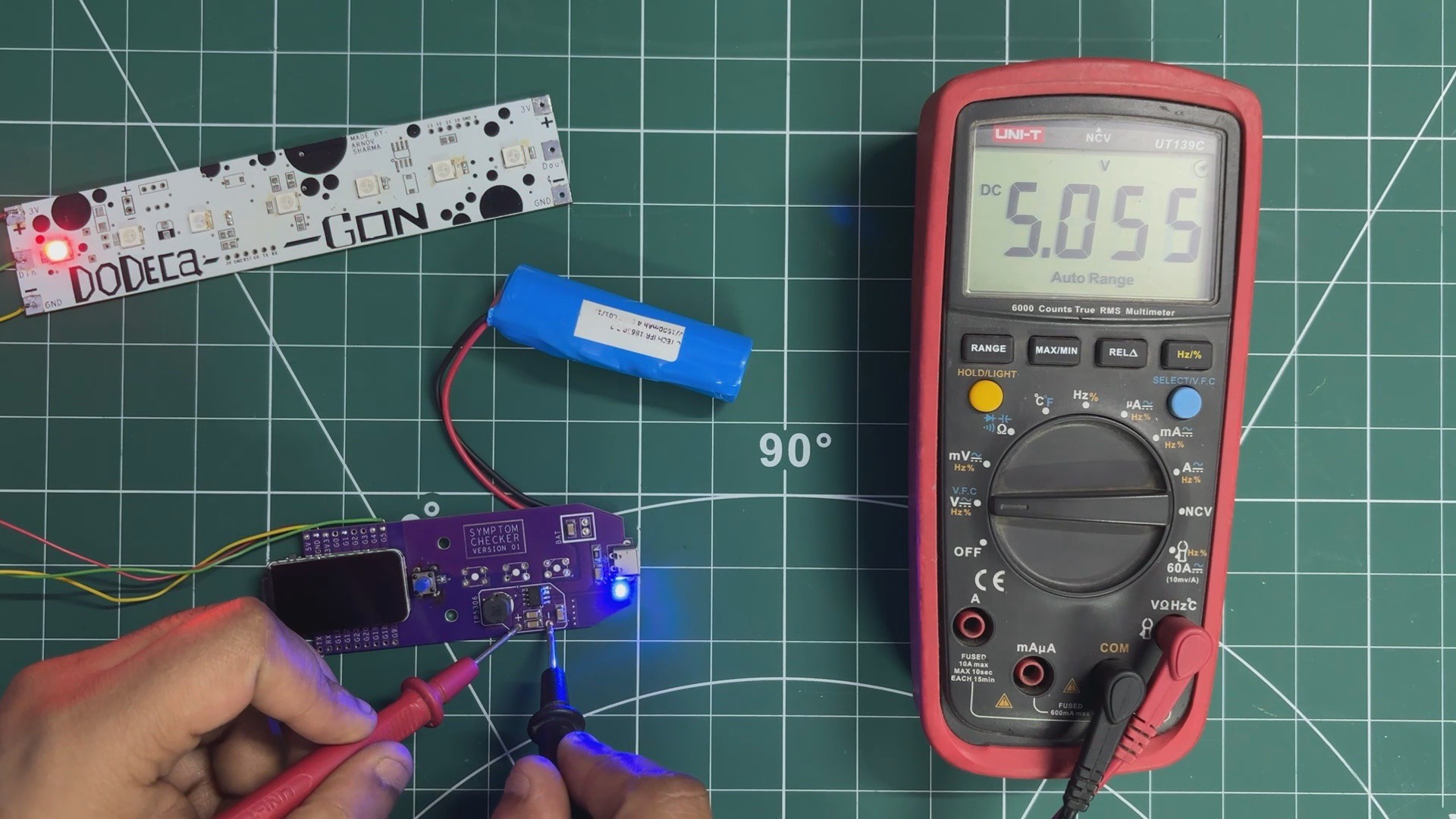
We’ll start with the Medic Mini mainboard. This board was reused because it already includes a reliable onboard power-management system that serves as the primary power source for the lamp. It features the IP5306 power-management IC, which operates from a single 3.7 V Li-ion cell and provides a stable 5 V output capable of delivering up to 2 A.
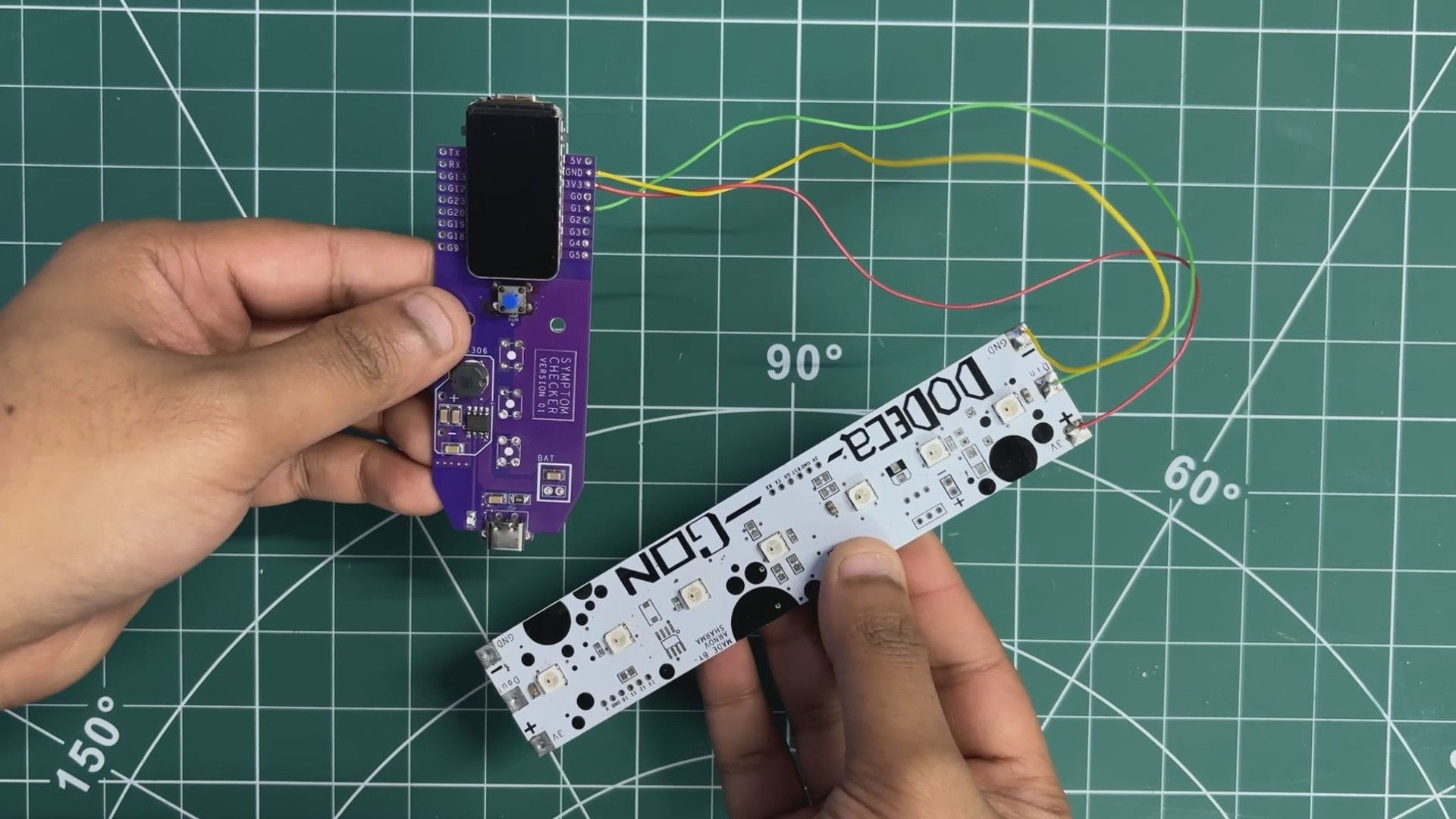
The board also integrates an ESP32-C6 development board, which acts as the main microcontroller for the project. Using the ESP32-C6 allows us to host a web application directly on the device, enabling the lamp to be controlled over a local network through a simple IP address.
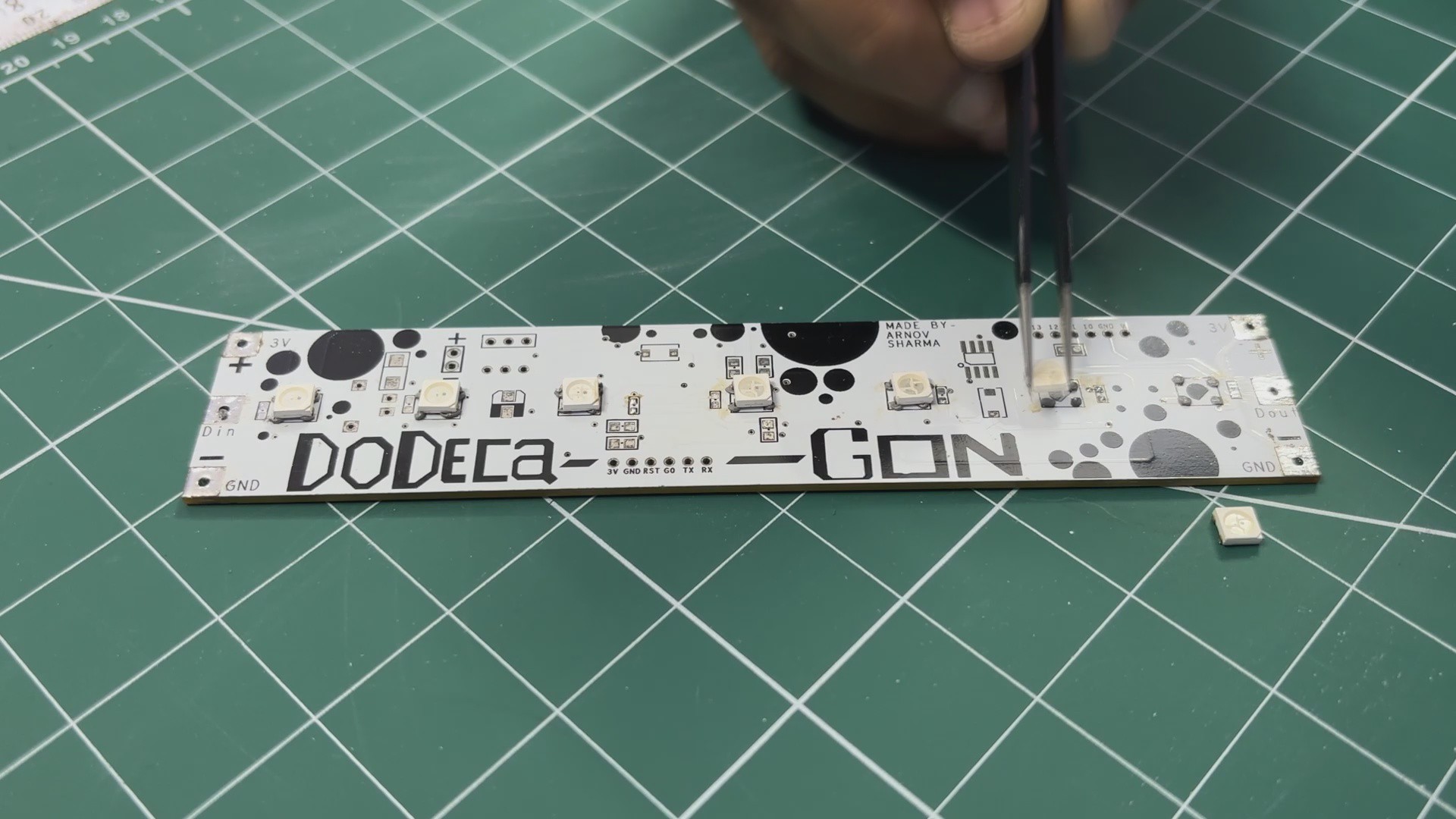
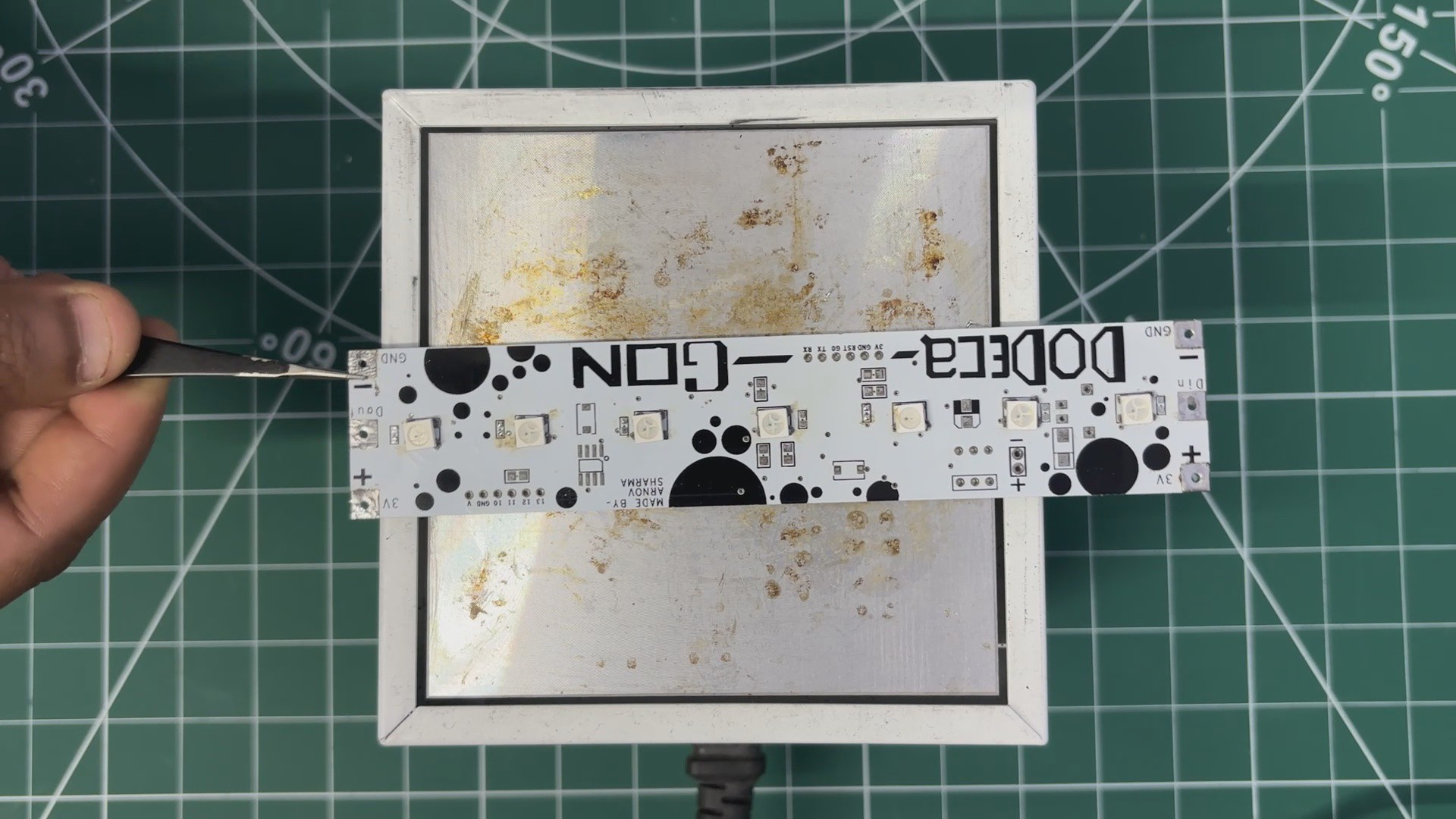
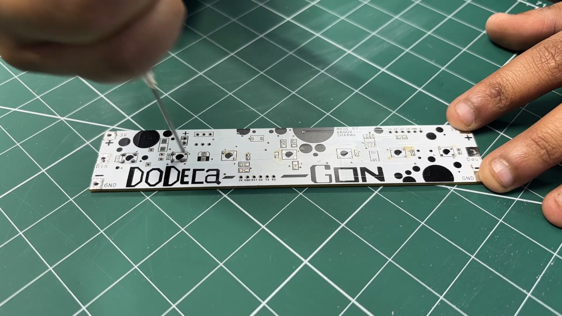
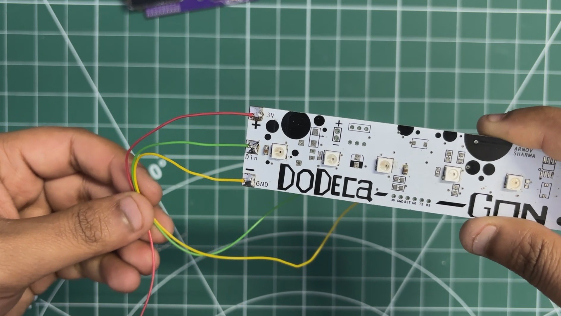
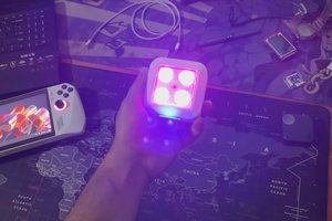
The second reused board is the Dodecagon RGB LED PCB. This PCB contains seven WS2812B RGB LEDs connected in series. It originally came from a project I built back in 2021, and we decided to repurpose it here as the primary lighting element. In this build, a glass brick is placed directly above the LED PCB, allowing the diffused light from the LEDs to illuminate the glass block evenly and create the lamp’s signature glow.
PCBWAY
For the project’s PCBs—the Dodecagon LED...
Read more »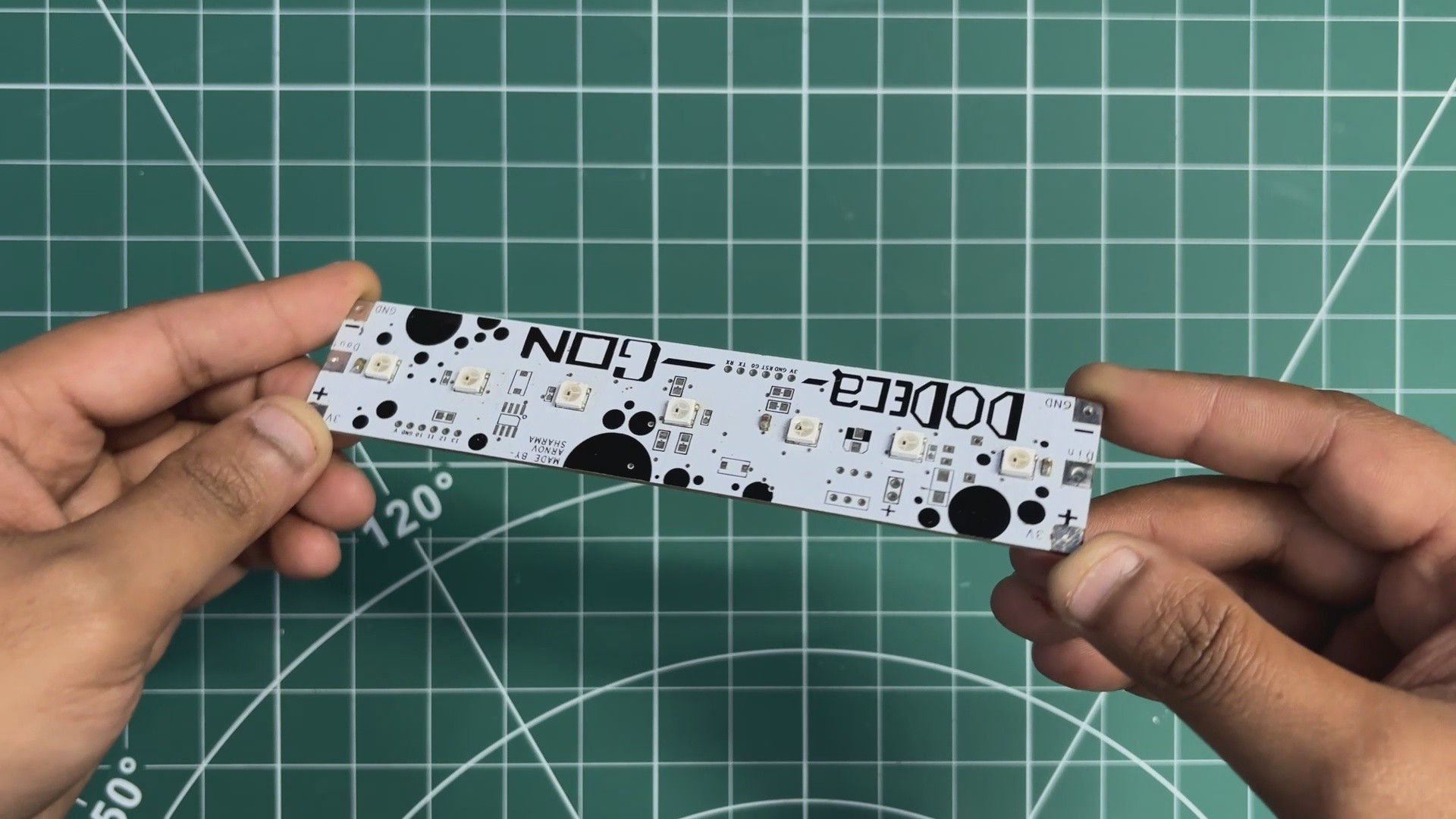


Awesome idea, looks fantastic!