Close
0%
0%

Mega Man's Mega Buster

Full-Size Working Replica of Mega Man's Mega Buster

Similar projects worth following
0 followers
Greetings everyone, and welcome back!
This is Mega Man’s Mega Buster, also known as the Rock Buster (or ROKKU BASUTA in Japan), which I built completely from scratch.
This is a fully working replica. I started by modeling the Mega Buster in Fusion 360 and then added electronics inside to replicate both the plasma blaster effect and the side power indicator. The entire setup is powered by a Raspberry Pi Pico, paired with a custom power circuit using a lithium battery, making it a wearable prop. I’ve also added an internal speaker to bring sound effects to life.

The goal of this project was simple: I’m planning to attend an upcoming Comic Con event in Gurugram, and I wanted to create a quick, wearable gauntlet-style prop. I won’t be wearing the full suit—just the gauntlet—and the Mega Buster is something I’ve always wanted to build. I used to play Mega Man X on my Windows 98 PC years ago. The game was brutally hard, but it was a big part of my childhood, and I wanted to bring a piece of that nostalgia into the real world. That’s why I chose the Mega Buster.

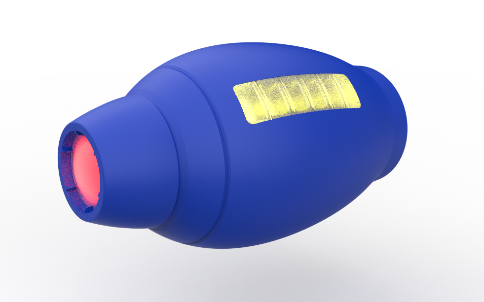
Here's how it works: inside the Mega Buster, there’s a push button used to trigger the firing sequence. When the button is pressed and held, the blaster begins charging and plays a charging sound effect. Once the button is released, the front red LED flickers, simulating the firing of a plasma beam.

The plasma beam remains active for the duration of the button press; the longer the button is held, the longer the beam fires. After firing, the effect slowly fades out and turns off.

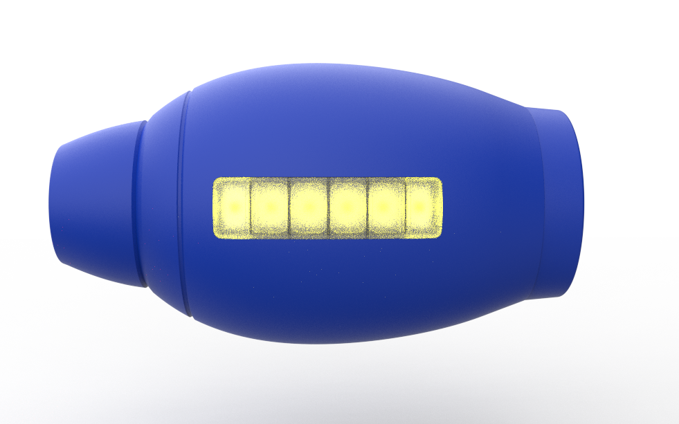
On the side of the blaster, there’s a six-bar power indicator that acts like an ammo meter. Each time the plasma beam is fired, one bar is depleted. Once all six bars are empty, the side indicator, front blaster LED, and speaker all blink red for 10 seconds, indicating a cooldown period. After the cooldown finishes, the device resets and power is fully restored.

This article covers the complete build process of the project from design to electronics and final assembly.

Let’s get started.

MEGAMAN

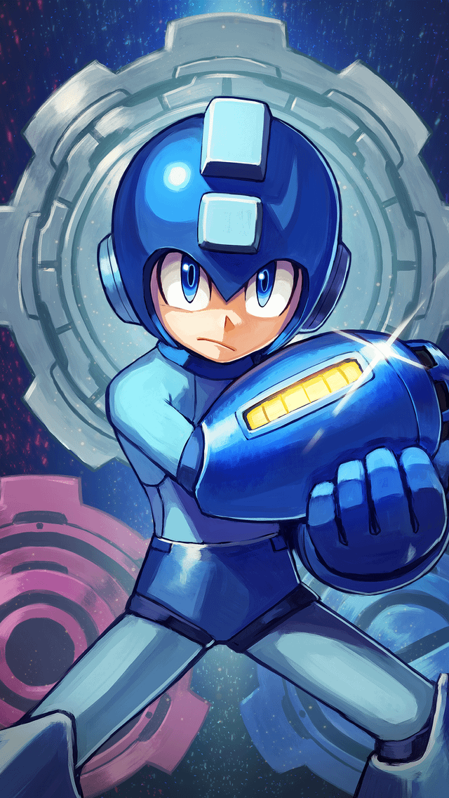
For anyone unfamiliar, Mega Man, also known as Rockman in Japan, is a classic action-platformer franchise created by Capcom. The series follows a humanoid robot named Mega Man, originally called Rock, who battles rogue robots using special weapons acquired from defeated enemies. One of the most iconic elements of the franchise is the Mega Buster, an arm-mounted energy cannon capable of firing charged energy shots.

Since its debut in the late 1980s, the Mega Man franchise has become known for its tight controls, memorable music, and challenging gameplay, earning a dedicated fan base across multiple generations.

My introduction to the Mega Man universe came through Mega Man X. Unlike the original Mega Man series, Mega Man X does not focus on the original Mega Man (Rock). Instead, the main protagonist is X, a new-generation robot created by Dr. Light. X is designed with the ability to think, feel, and make moral decisions, which gives the Mega Man X series a darker and more mature tone compared to the classic games.

Another major difference introduced in the Mega Man X series is Zero. Zero is a powerful ally and sometimes rival who uses a beam saber instead of an arm cannon. While early Mega Man X games focus mainly on X, later titles allow players to switch between X and Zero, each offering distinct fighting styles, abilities, and upgrades.

Now that the basics are covered, let’s move on to the project.

https://megaman.fandom.com/wiki/Mega_Man_Knowledge_Base

DESIGN

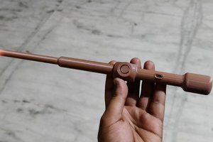
We start the 3D model-making process by first getting a reference image of the Rock Buster from the internet. We import the image into Fusion 360 through the canvas option, then use the calibration function to set the length of the whole gauntlet to 330 mm.

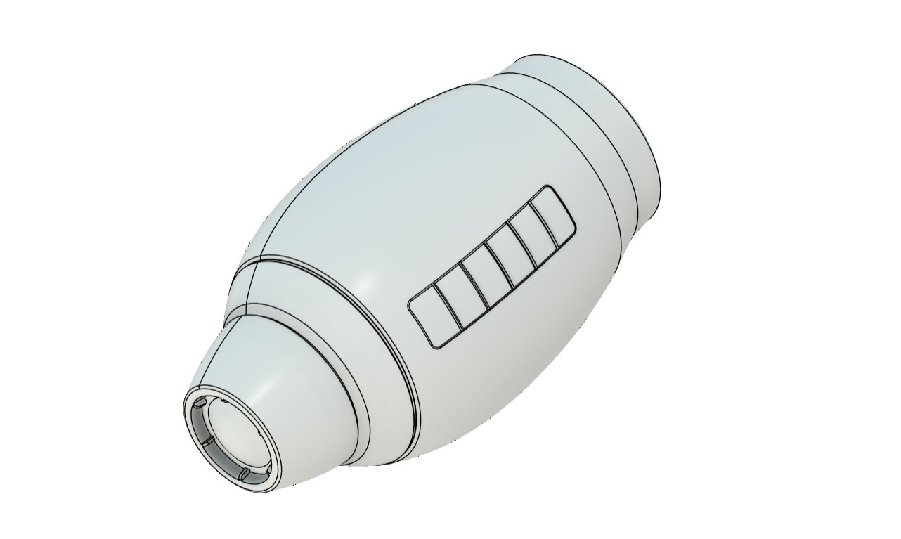
The whole gauntlet is symmetrical, so we can easily make this using the revolve function. To do this, we trace the outline of the gauntlet and then use the revolve function to make a solid gauntlet body.

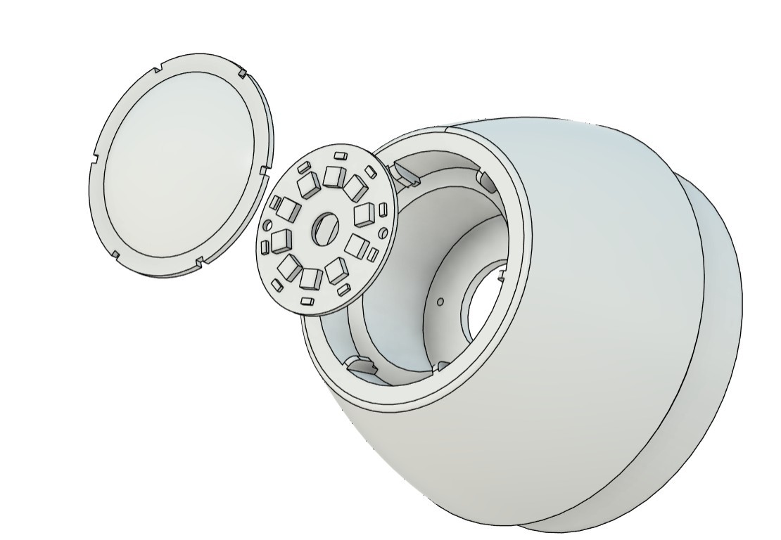
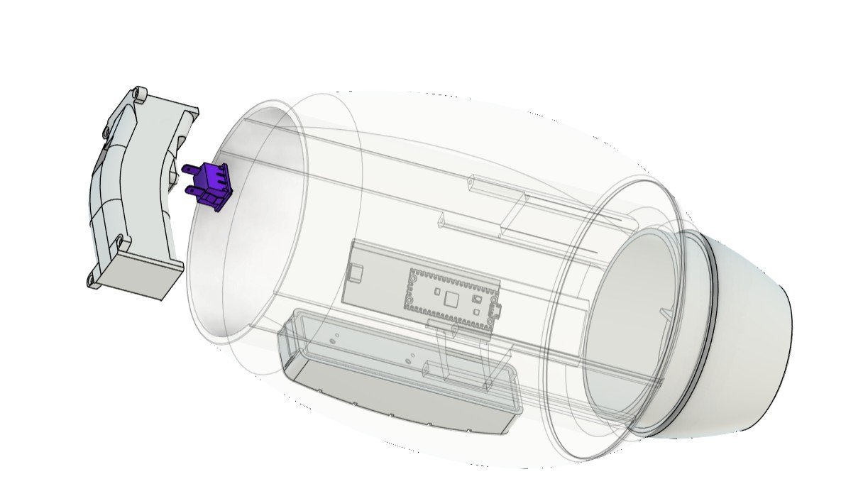
For the engineering process, we first divide the body into three main sections. The front part is the blaster section, the middle body is a hollow part in which we add the handle grip that is used to hold the whole gauntlet, and inside this section we also add the main control circuit. The third part is the back section, which contains a cushion that supports our arm.

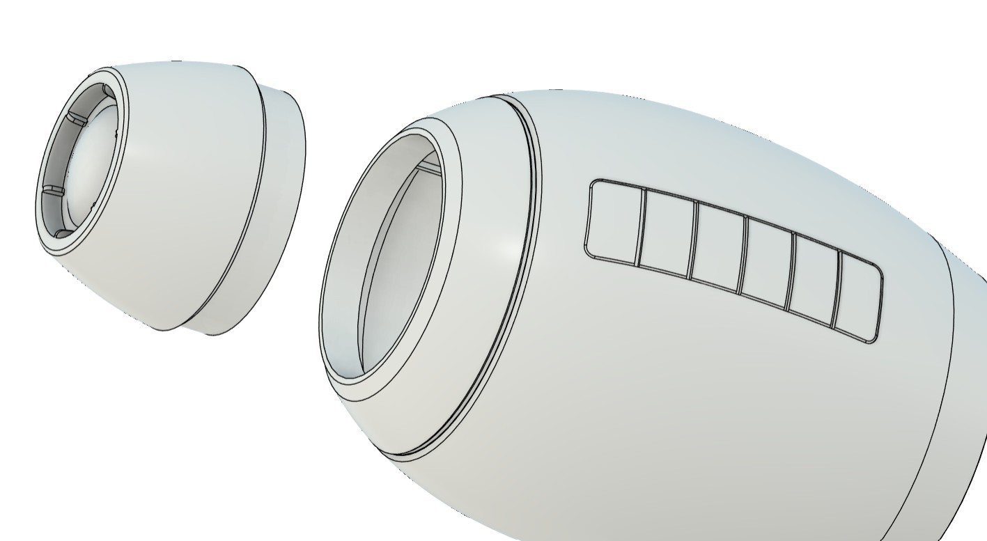
The middle body, or main body, on the left side contains a replica of the yellow power bar. This part is basically a slot...

Read more »

MAIN BODY.stl

Standard Tesselated Geometry - 12.28 MB - 02/10/2026 at 09:25

Download

FRONT.stl

Standard Tesselated Geometry - 8.05 MB - 02/10/2026 at 09:25

Download

Megaman v13.f3d

fusion - 8.34 MB - 02/10/2026 at 09:25

Download

Handle.stl

Standard Tesselated Geometry - 2.69 MB - 02/10/2026 at 09:25

Download

SIDE.stl

Standard Tesselated Geometry - 3.87 MB - 02/10/2026 at 09:25

Download

View all 9 files

  • 1
    PCB ASSEMBLY PROCESS- MAIN CIRCUIT
    • We begin the main board assembly process by first adding solder paste to each component pad using a solder paste dispensing syringe. We are using SnPb 63/37 solder paste here, which has a melting temperature of 200°C.
    • Next, we pick and place the Raspberry Pi Pico in its location over the footprint, followed by all the SMD components.
    • The whole circuit is then placed on a reflow hot plate, which heats the PCB from below up to the solder paste melting temperature. When the PCB reaches 200°C, the solder paste melts and all components are secured in their locations.
    • Next, we add the Type-C port in its location, followed by the vertical push button.
    • The board is then flipped over, and the leads of the Type-C port and push button are secured using solder.
  • 2
    POWER SOURCE TEST

    For the power source of this project, a 3.7 V, 1000 mAh lithium-polymer (Li-Po) cell is used. The positive terminal of the battery is connected to the B+ terminal on the main board, while the negative terminal is connected to B−.

    A vertical push button is used as the power switch. When the button is pressed, the circuit powers on.

    To verify proper operation, a multimeter is used to measure the voltage across the 5 V and GND pins on the main board. A stable reading of 5 V confirms that the power circuit is functioning correctly and the setup is ready for operation.

  • 3
    MAIN BOARD AUDIO MODULE ASSEMBLY & DEMO

    A speaker cannot be connected directly to the Raspberry Pi Pico’s GPIO pins for practical audio output. While it may work electrically, the sound level is extremely low and not suitable for a wearable prop. To solve this, an external audio amplifier is required to boost the Pico’s audio signal.

    For this project, I used the PAM8403 audio amplifier module. The PAM8403 is a compact Class-D amplifier capable of driving small speakers efficiently.

    The wiring was done as follows:

    • PAM8403 R input to GPIO26 of the Raspberry Pi Pico
    • PAM8403 GND to GND
    • PAM8403 5V to 5V output from the custom power circuit

    For the speaker, I used an 8-ohm, 2-watt speaker salvaged from an old laptop. The speaker was connected to the R output terminals of the PAM8403 amplifier board.

    After completing the wiring, a simple test sketch was uploaded to the Pico.

    The speaker successfully produced a stable beep for a few seconds, turned off, and then repeated the sequence in a loop. This confirmed that the amplifier and speaker setup were working perfectly.

    #define AUDIO_PIN 26
    #define BLAST_TIME   2000
    #define SILENT_TIME  2000
    void setup() {
    pinMode(AUDIO_PIN, OUTPUT);
    }
    void loop() {
    unsigned long start = millis();
    while (millis() - start < BLAST_TIME) {
    // Fast pitch sweep = blaster feel
    for (int f = 1200; f > 400; f -= 30) {
    tone(AUDIO_PIN, f);
    delay(2);
    }
    }
    noTone(AUDIO_PIN);
    delay(SILENT_TIME);
    }


View all 13 instructions

Enjoy this project?

Share

Discussions

Similar Projects

Does this project spark your interest?

Become a member to follow this project and never miss any updates