 Arnov Sharma
-
1PCB ASSEMBLY PROCESS- MAIN CIRCUIT
![]()
![]()
![]()
![]()
![]()
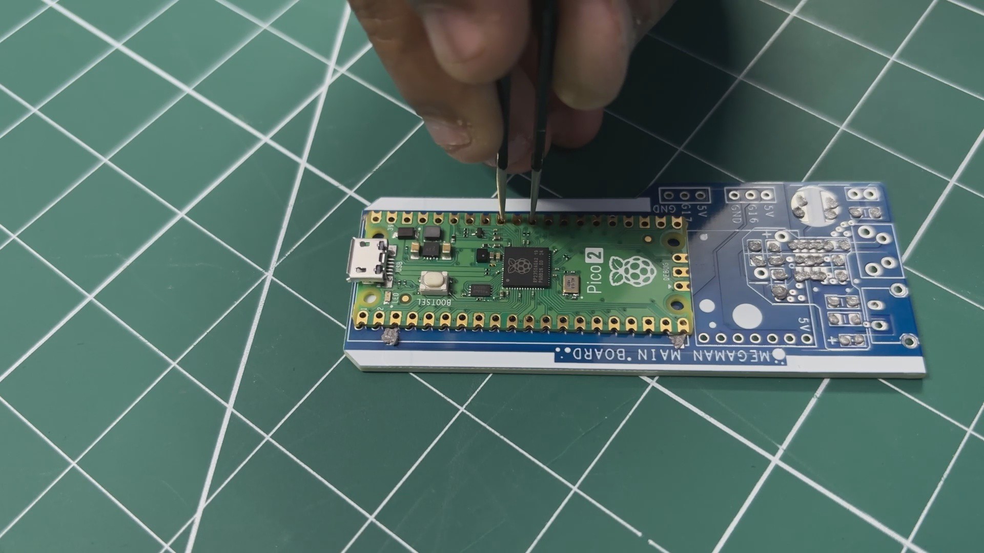
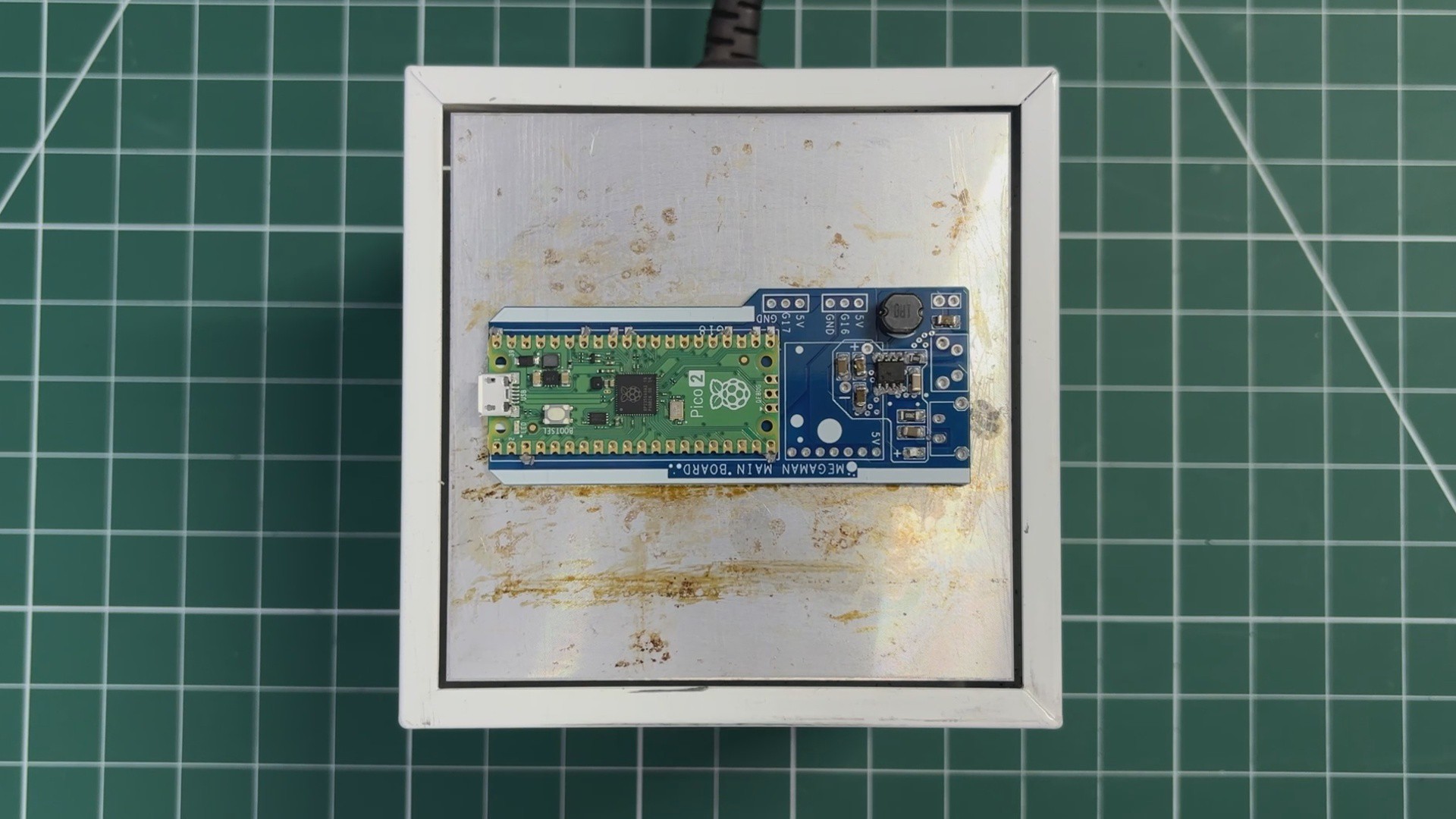
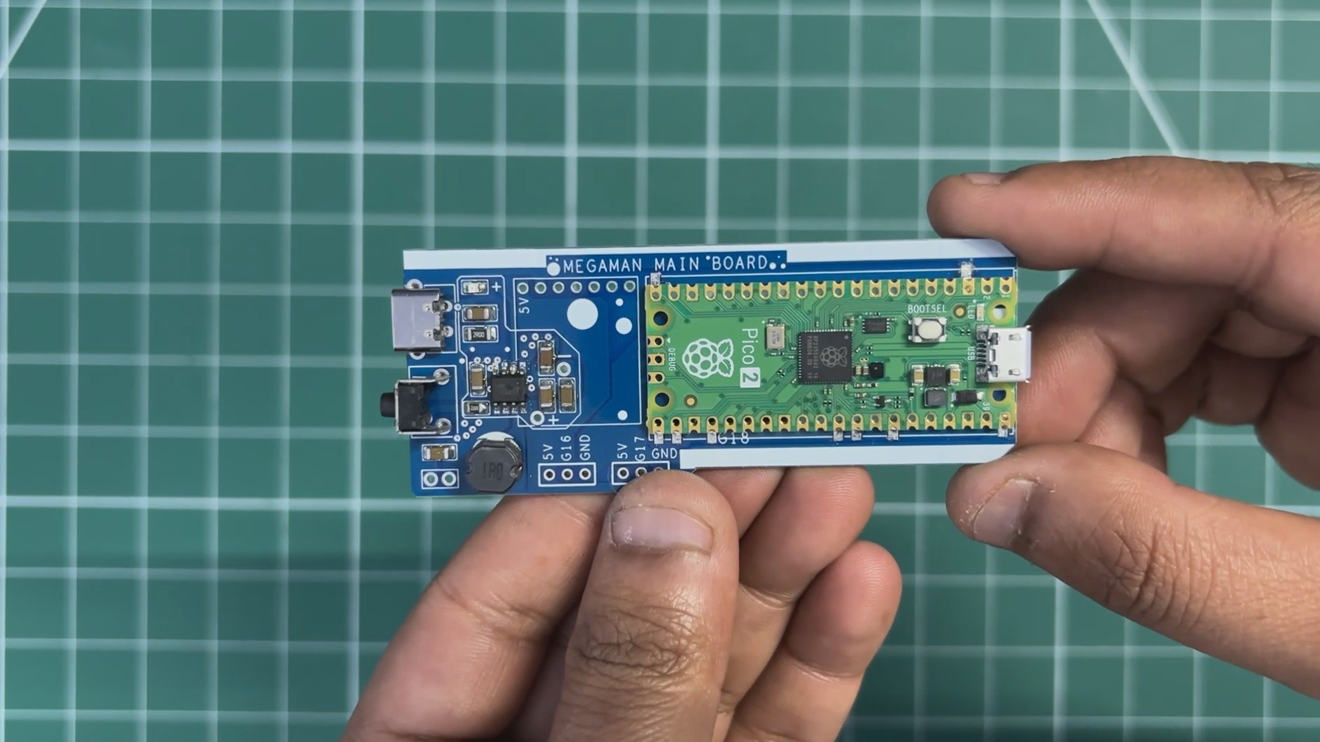
- We begin the main board assembly process by first adding solder paste to each component pad using a solder paste dispensing syringe. We are using SnPb 63/37 solder paste here, which has a melting temperature of 200°C.
- Next, we pick and place the Raspberry Pi Pico in its location over the footprint, followed by all the SMD components.
- The whole circuit is then placed on a reflow hot plate, which heats the PCB from below up to the solder paste melting temperature. When the PCB reaches 200°C, the solder paste melts and all components are secured in their locations.
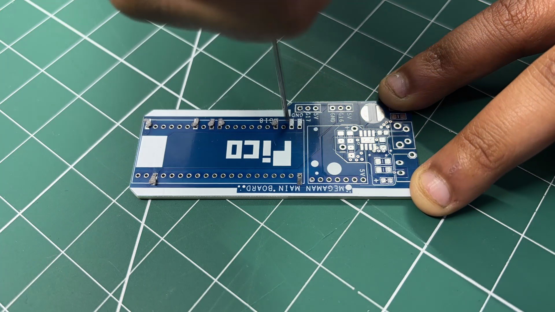
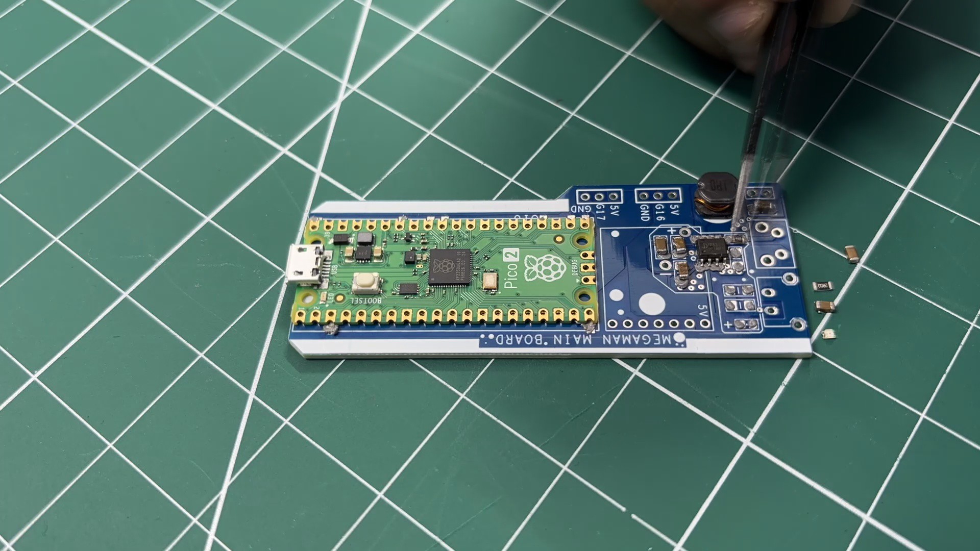
- Next, we add the Type-C port in its location, followed by the vertical push button.
- The board is then flipped over, and the leads of the Type-C port and push button are secured using solder.
-
2POWER SOURCE TEST
![]()
![]()
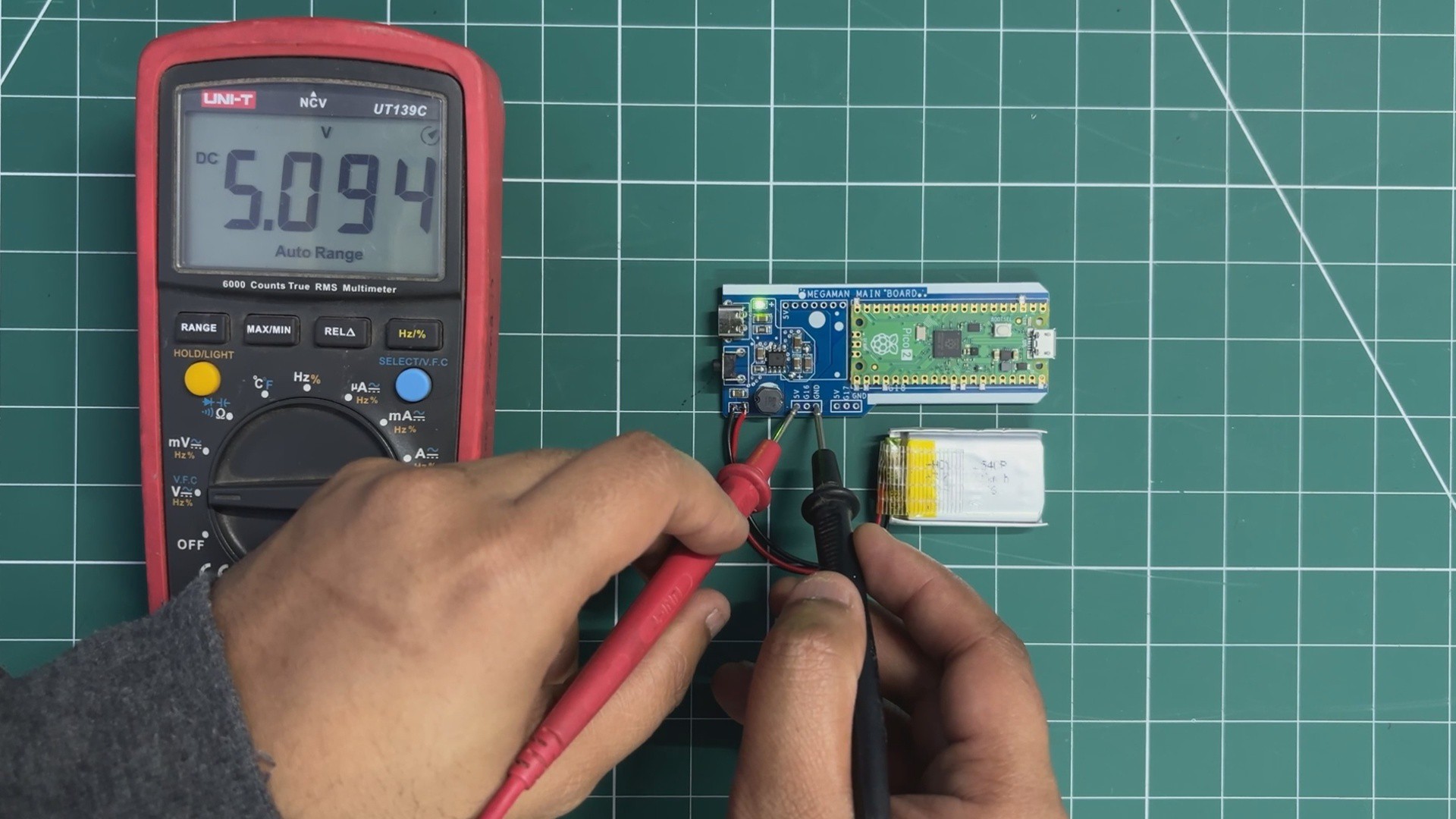
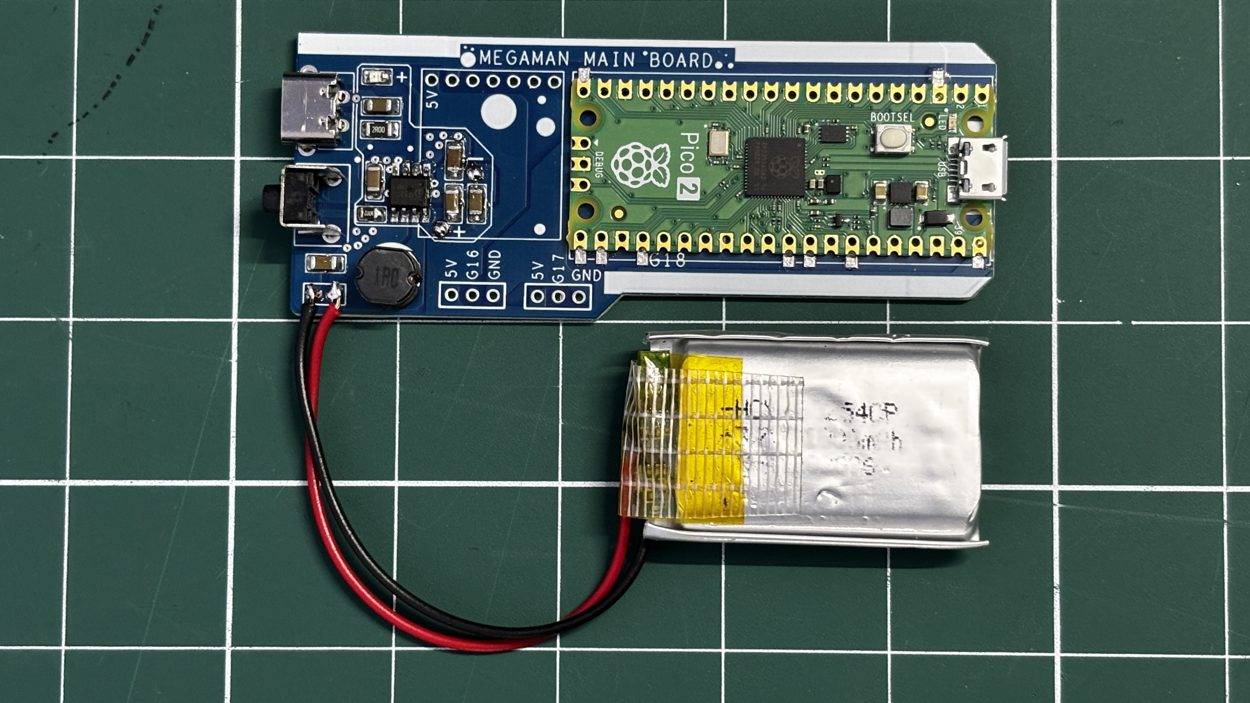
For the power source of this project, a 3.7 V, 1000 mAh lithium-polymer (Li-Po) cell is used. The positive terminal of the battery is connected to the B+ terminal on the main board, while the negative terminal is connected to B−.
A vertical push button is used as the power switch. When the button is pressed, the circuit powers on.
To verify proper operation, a multimeter is used to measure the voltage across the 5 V and GND pins on the main board. A stable reading of 5 V confirms that the power circuit is functioning correctly and the setup is ready for operation.
-
3MAIN BOARD AUDIO MODULE ASSEMBLY & DEMO
![]()
![]()
![]()
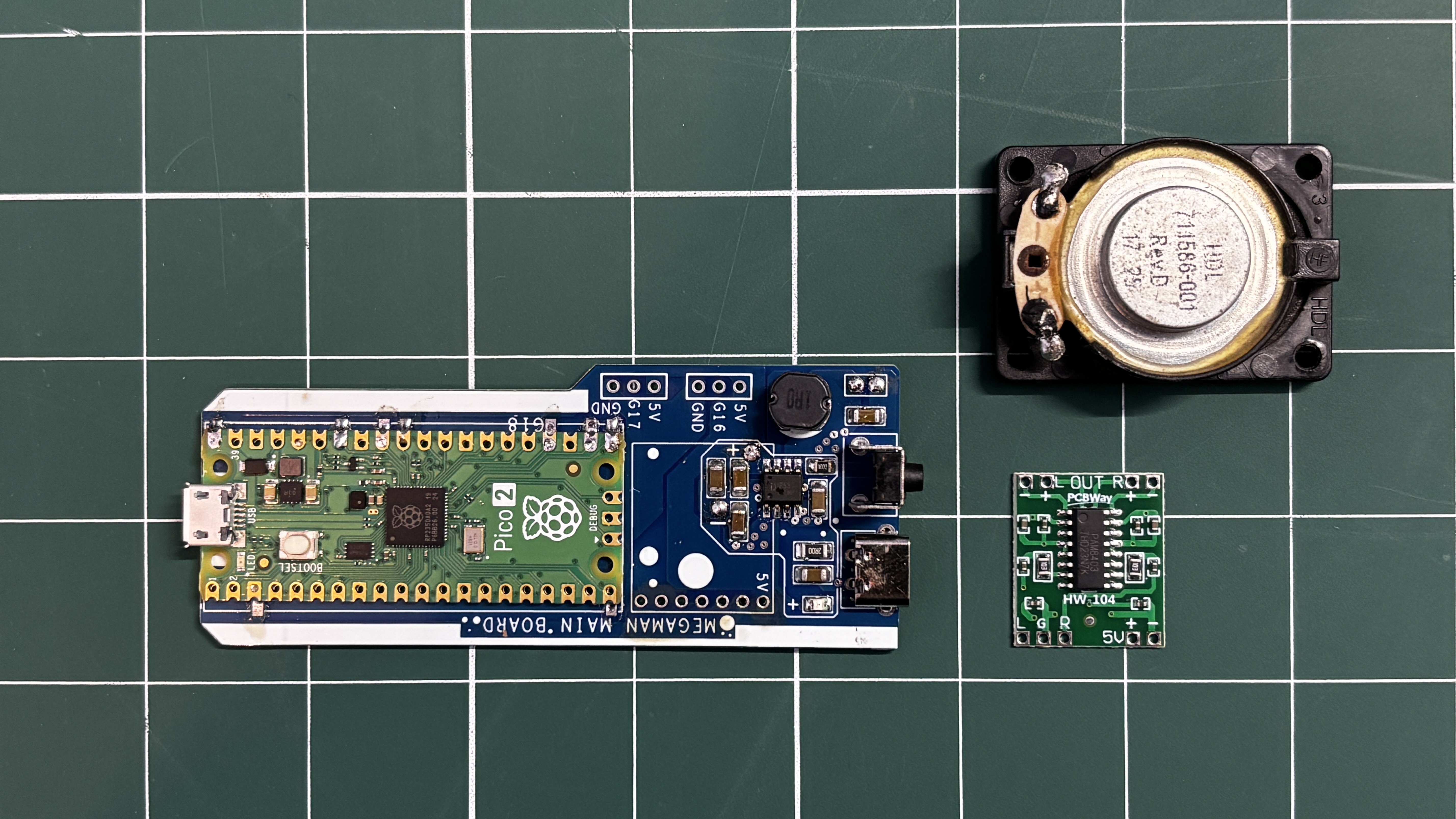
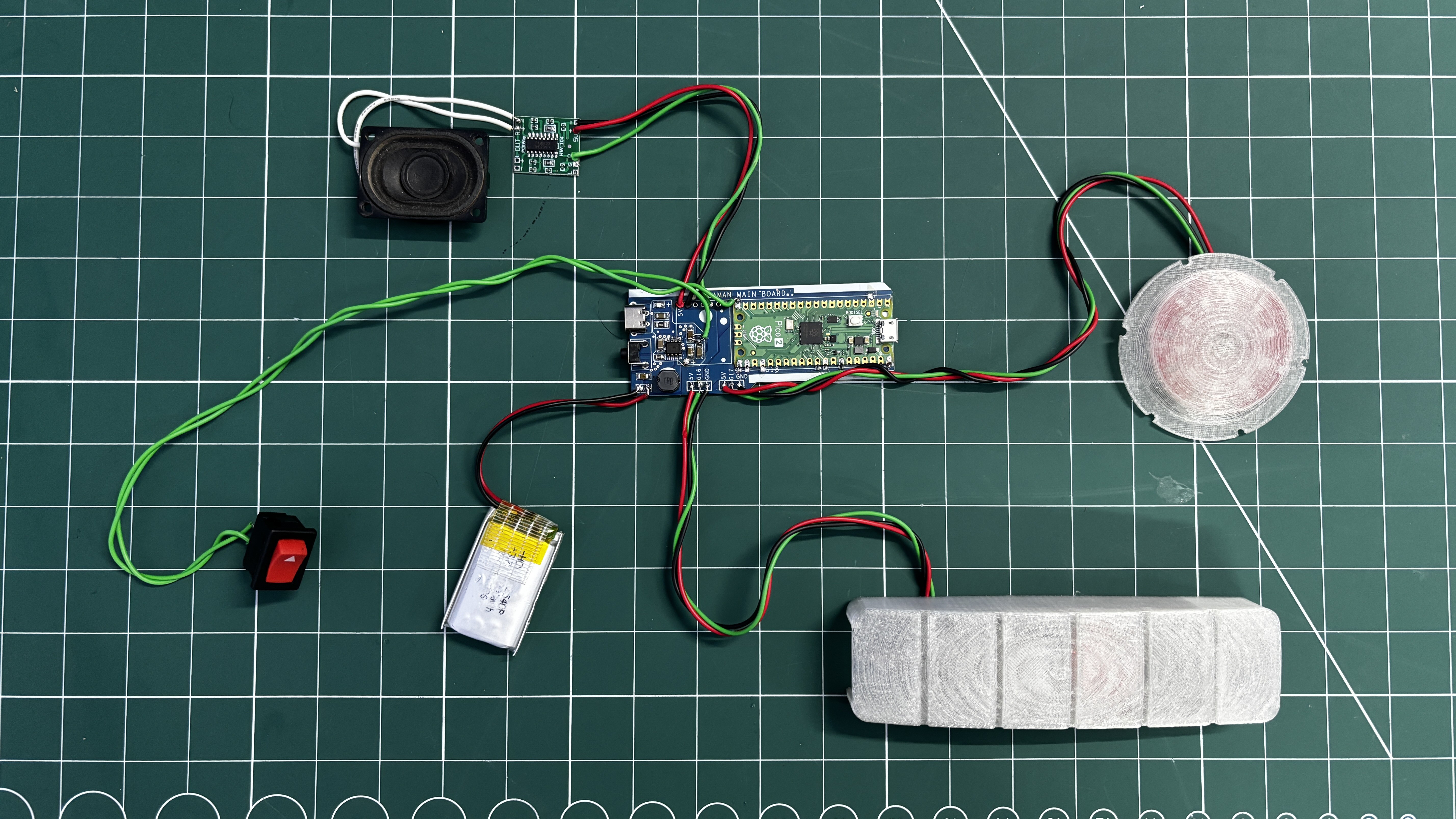
A speaker cannot be connected directly to the Raspberry Pi Pico’s GPIO pins for practical audio output. While it may work electrically, the sound level is extremely low and not suitable for a wearable prop. To solve this, an external audio amplifier is required to boost the Pico’s audio signal.
For this project, I used the PAM8403 audio amplifier module. The PAM8403 is a compact Class-D amplifier capable of driving small speakers efficiently.
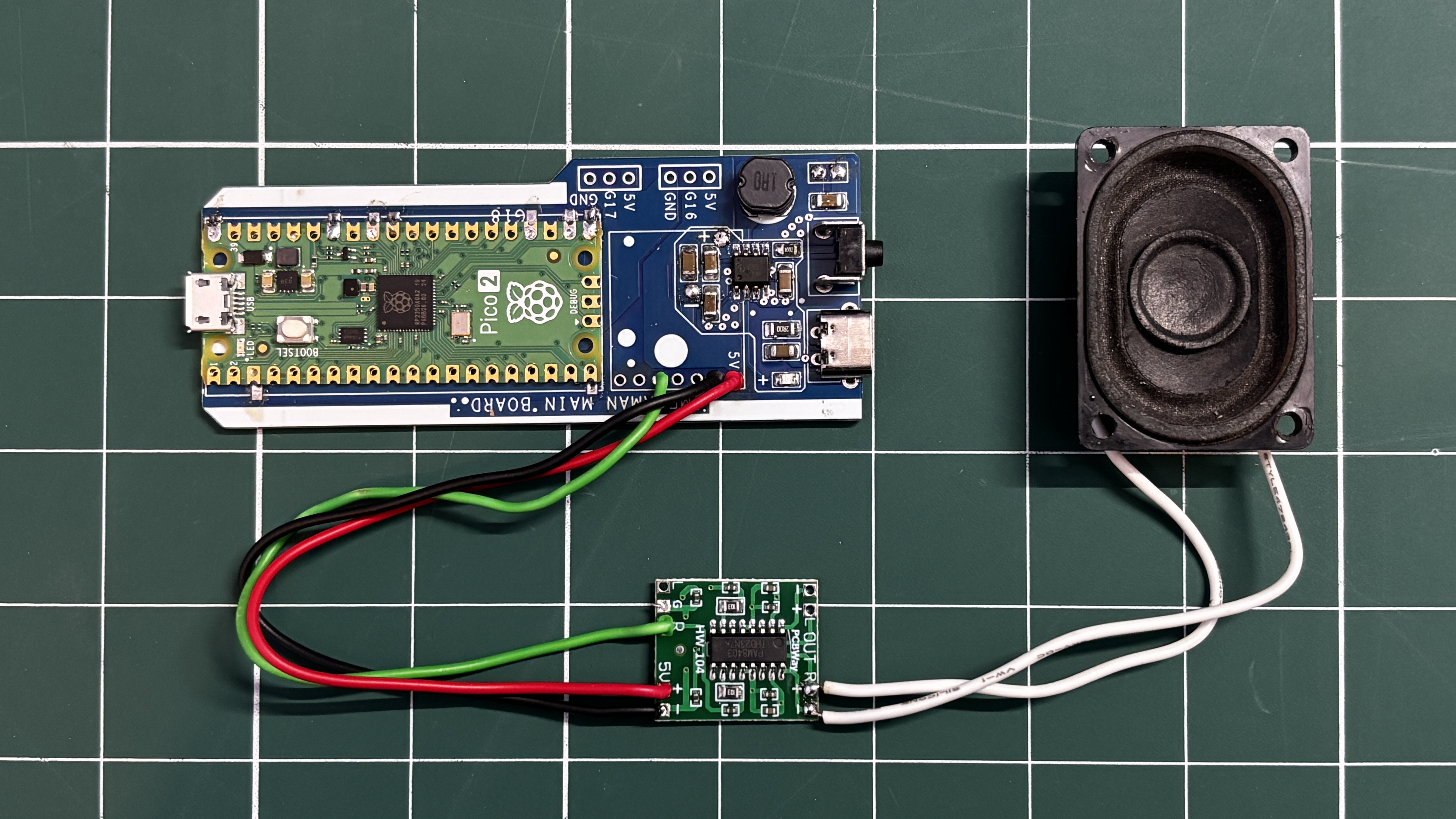
The wiring was done as follows:
- PAM8403 R input to GPIO26 of the Raspberry Pi Pico
- PAM8403 GND to GND
- PAM8403 5V to 5V output from the custom power circuit
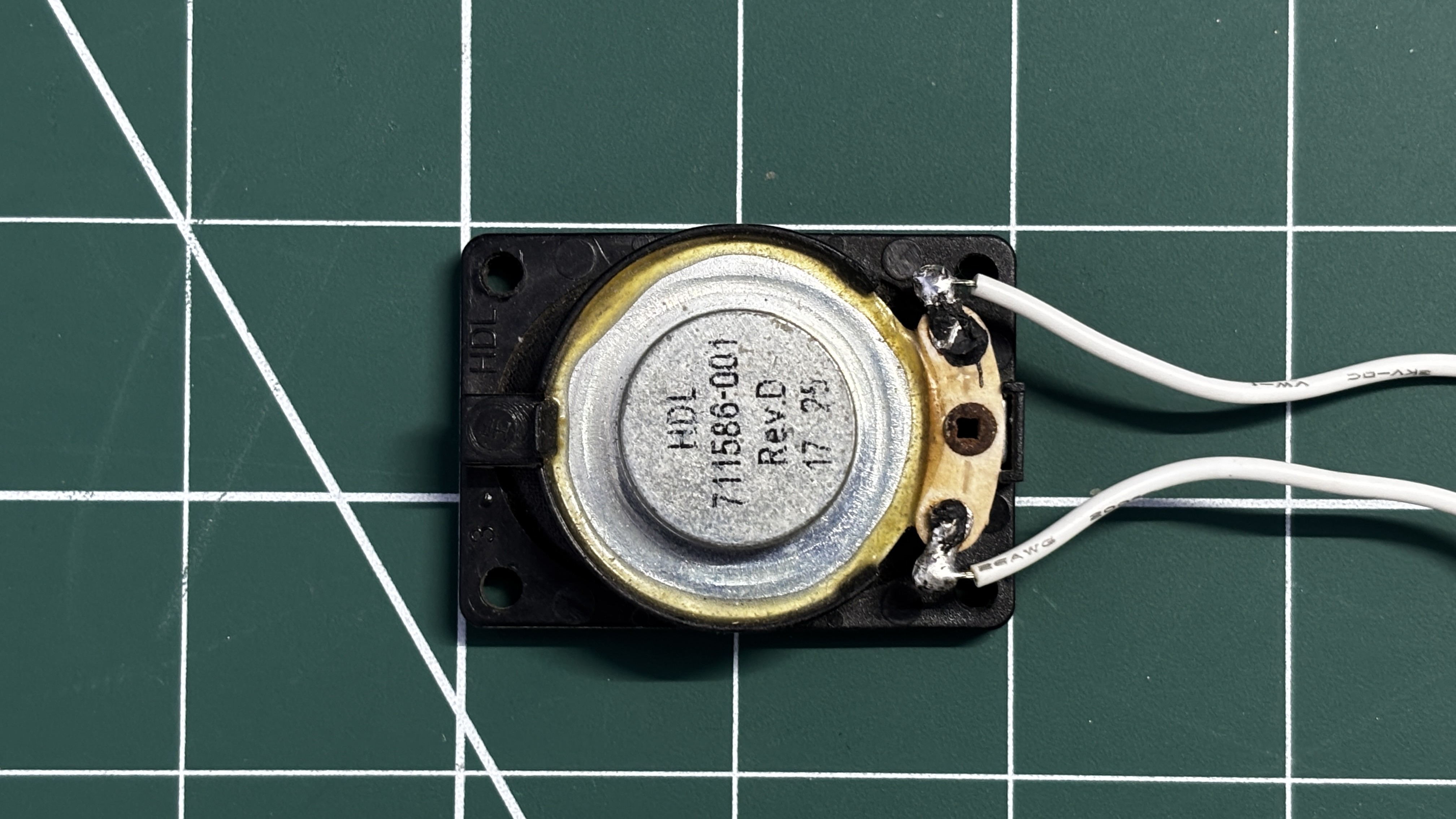
For the speaker, I used an 8-ohm, 2-watt speaker salvaged from an old laptop. The speaker was connected to the R output terminals of the PAM8403 amplifier board.
After completing the wiring, a simple test sketch was uploaded to the Pico.
The speaker successfully produced a stable beep for a few seconds, turned off, and then repeated the sequence in a loop. This confirmed that the amplifier and speaker setup were working perfectly.
#define AUDIO_PIN 26 #define BLAST_TIME 2000 #define SILENT_TIME 2000 void setup() { pinMode(AUDIO_PIN, OUTPUT); } void loop() { unsigned long start = millis(); while (millis() - start < BLAST_TIME) { // Fast pitch sweep = blaster feel for (int f = 1200; f > 400; f -= 30) { tone(AUDIO_PIN, f); delay(2); } } noTone(AUDIO_PIN); delay(SILENT_TIME); } -
4PCB ASSEMBLY-FRONT BLASTER
![]()
![]()
![]()
![]()
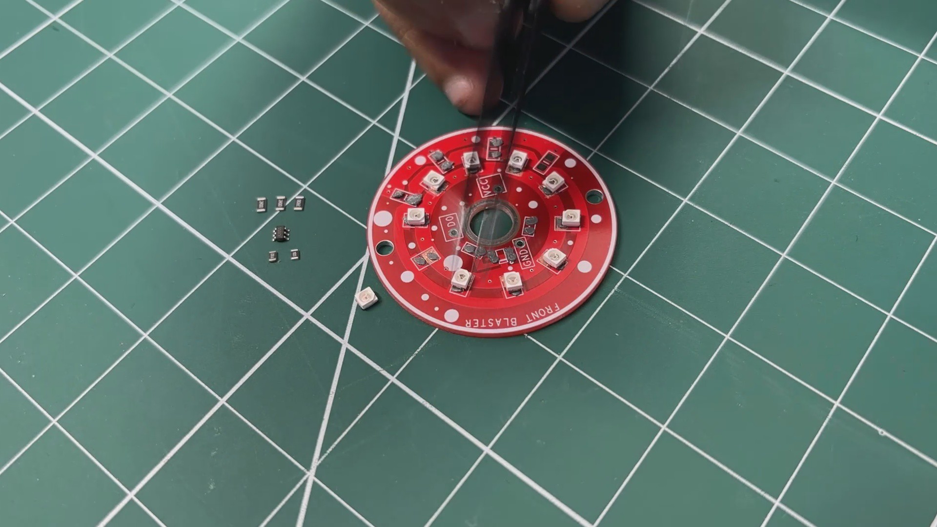
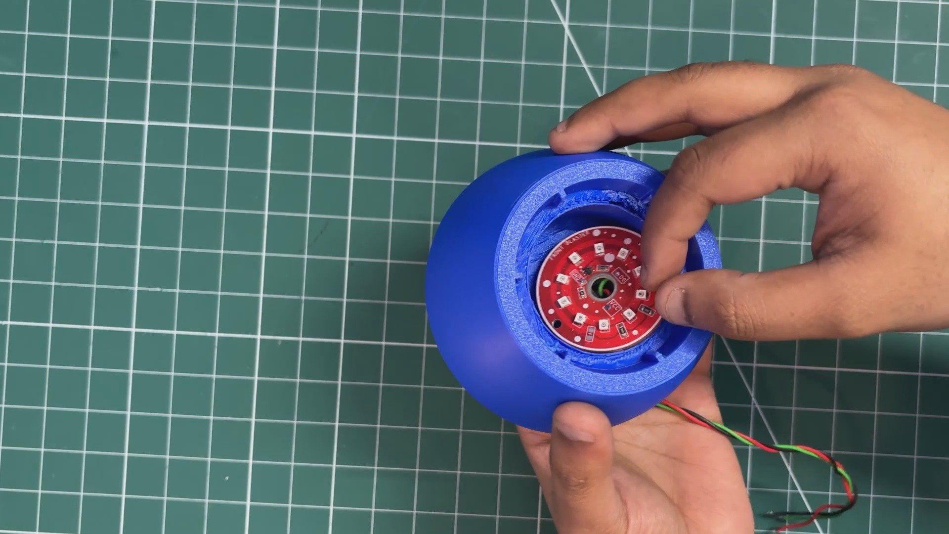
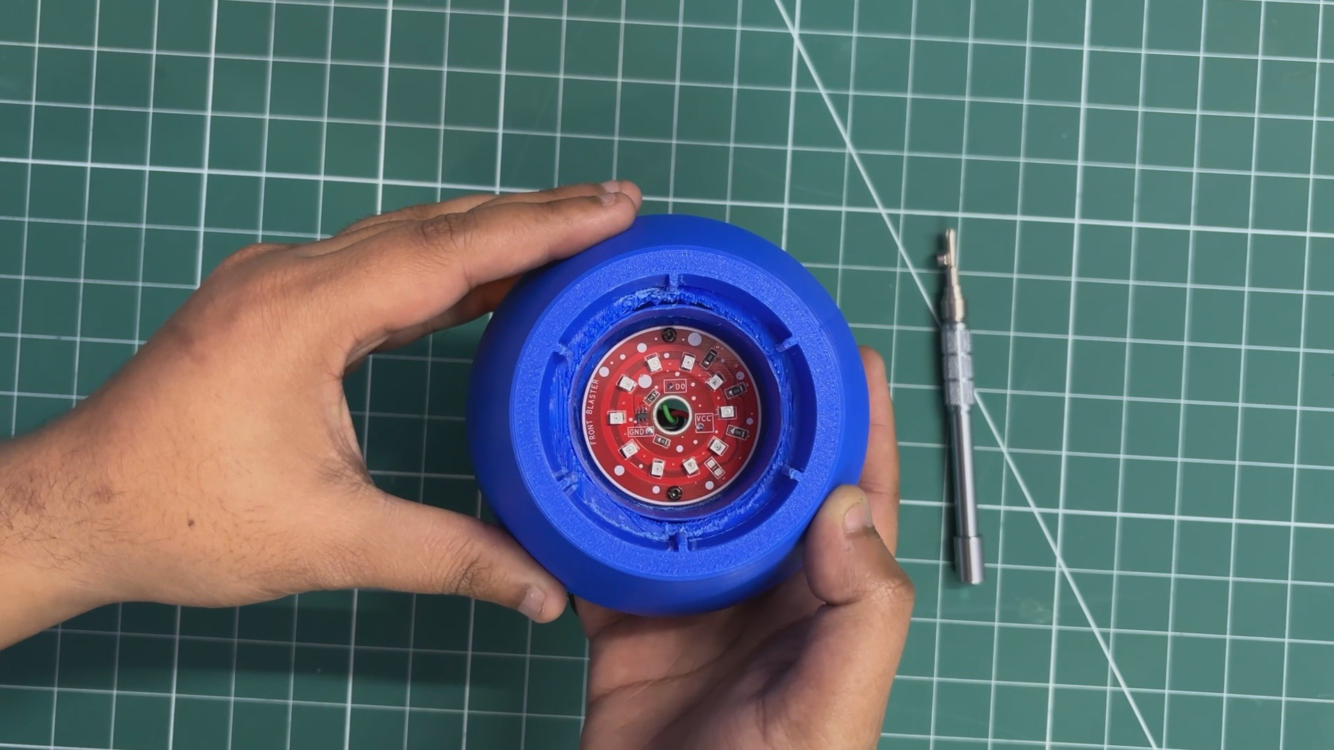
Next, we begin the assembly process of the front blaster PCB.
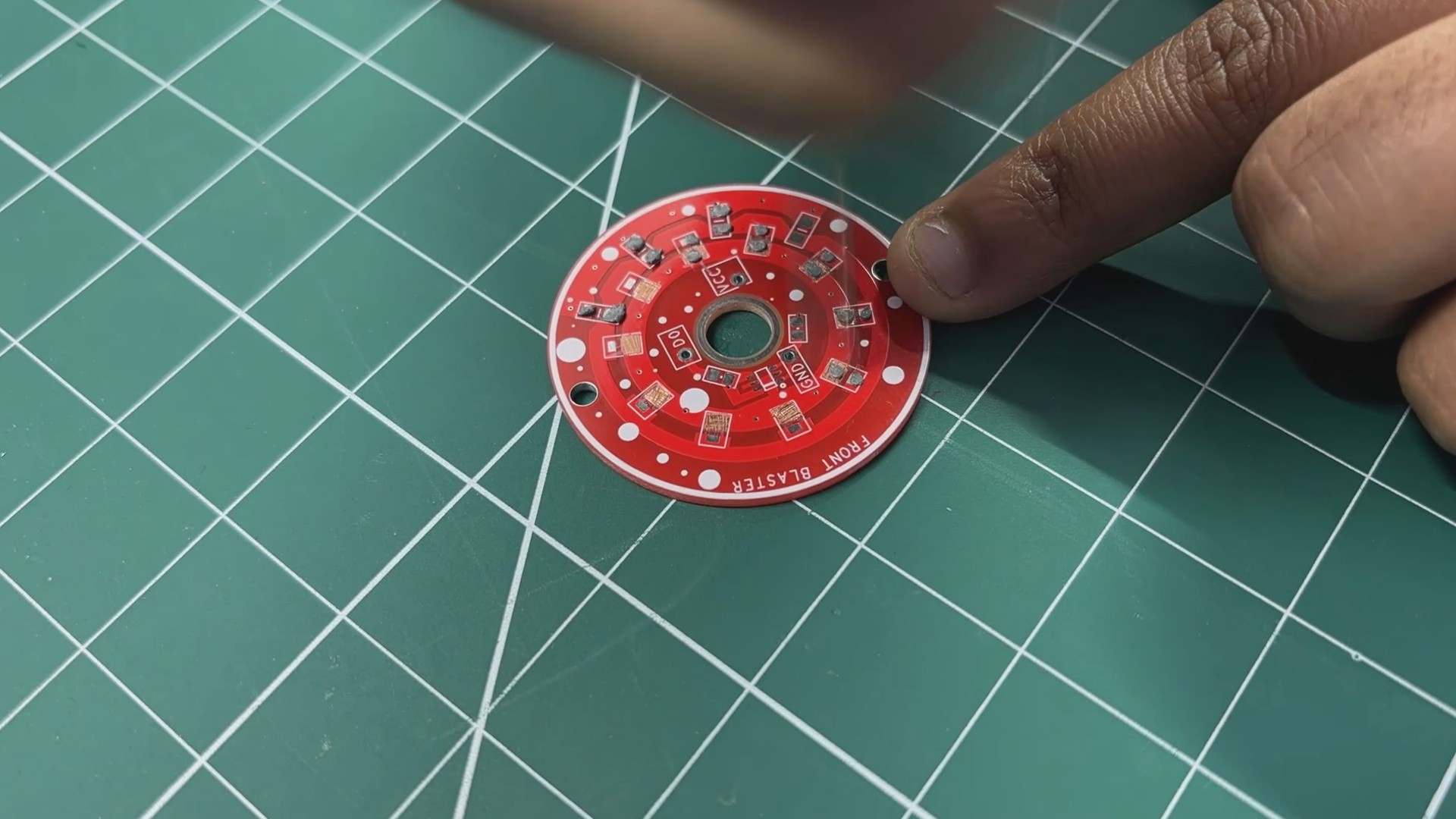
- The process starts by applying solder paste to each component pad on the PCB.
- Once the solder paste is applied, the SMD red 2835 LEDs are placed onto their respective footprints. This is followed by placing the MOSFET IC and the SMD resistors, using tweezers to accurately position each component.
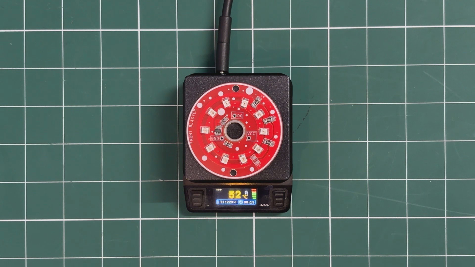
- After all components are placed, the PCB is carefully transferred to a reflow hot plate. The hot plate heats the PCB from below until it reaches the solder paste melting temperature. As the board reaches 200°C, the solder paste reflows and securely bonds all components to the PCB.
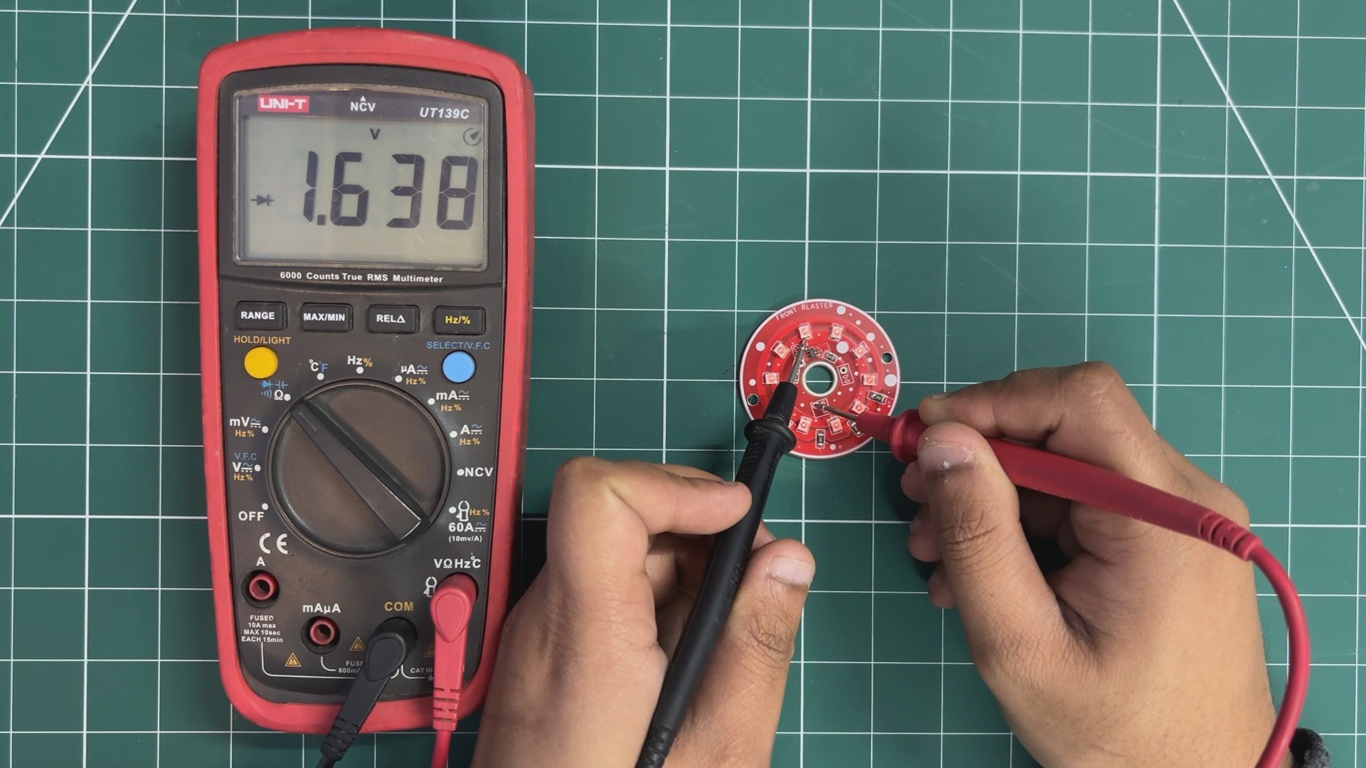
- To verify that all LEDs are soldered correctly, a multimeter set to diode test mode is used. The positive probe is placed on the VCC rail of the LED board, while the negative probe is connected to the drain terminal of the MOSFET. If all LEDs illuminate, it confirms that the soldering and connections are correct.
-
5PCB ASSEMBLY PROCESS- SIDE POWER INDIACTOR LED BOARD
![]()
![]()
![]()
![]()
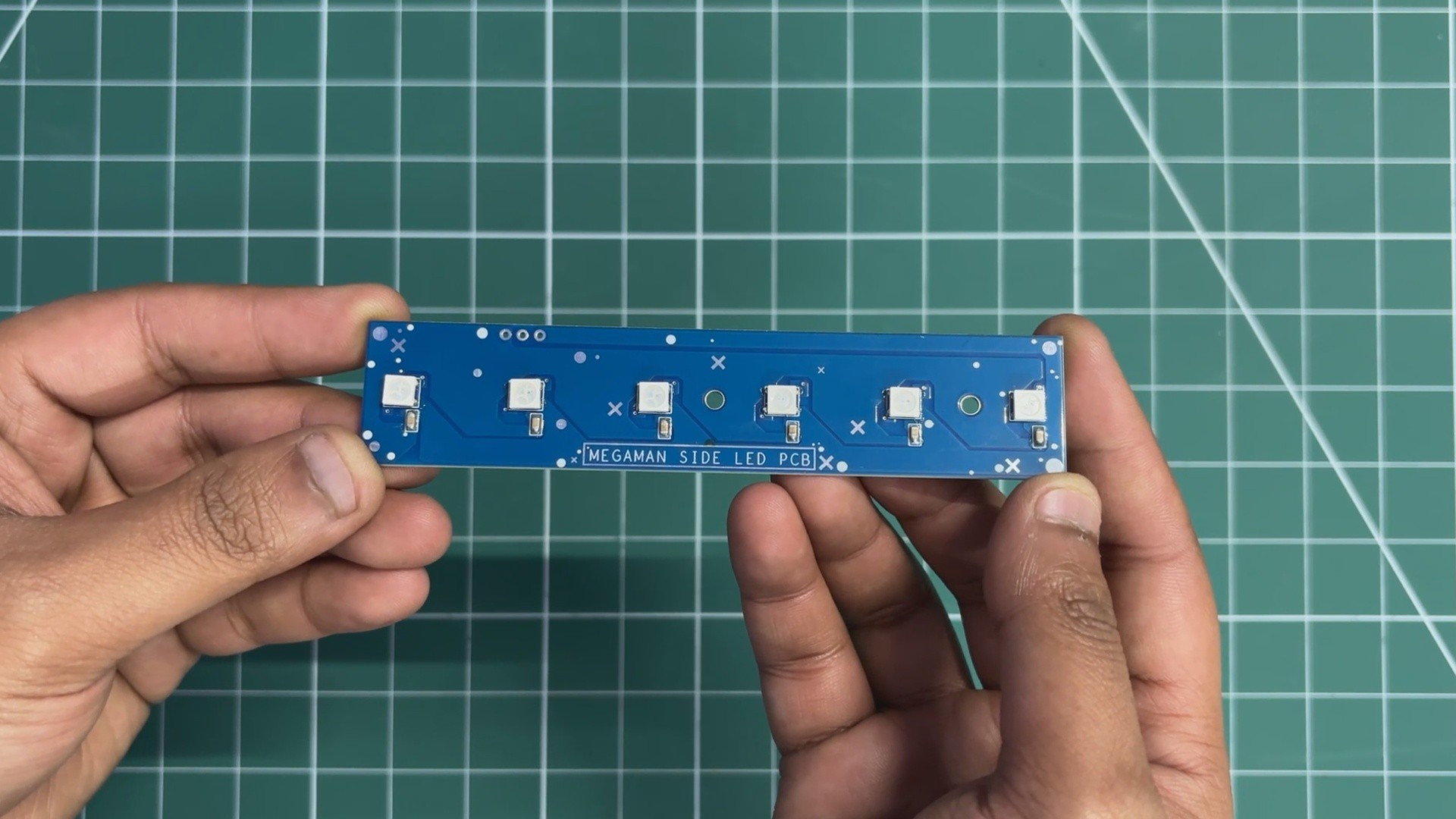
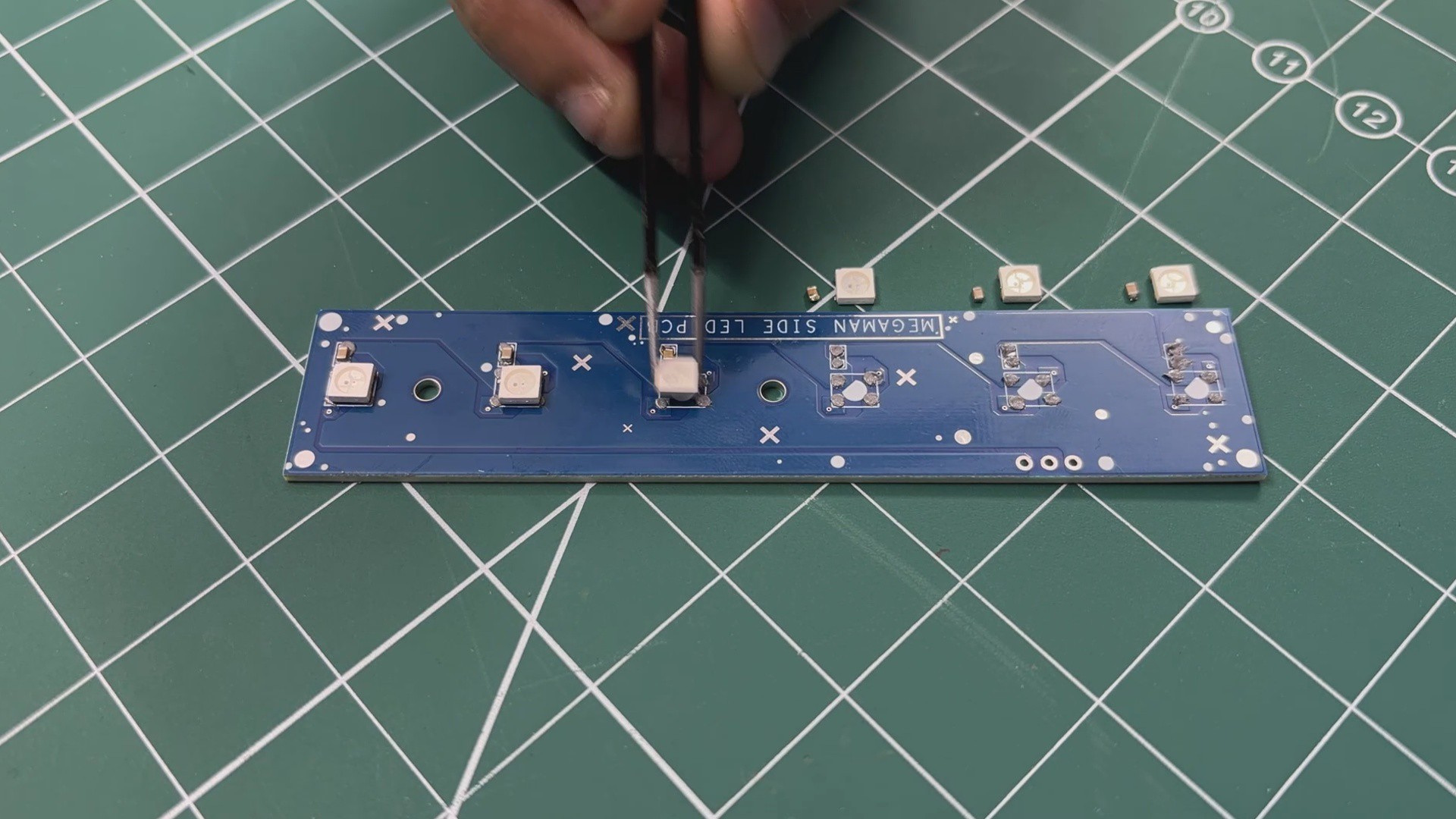
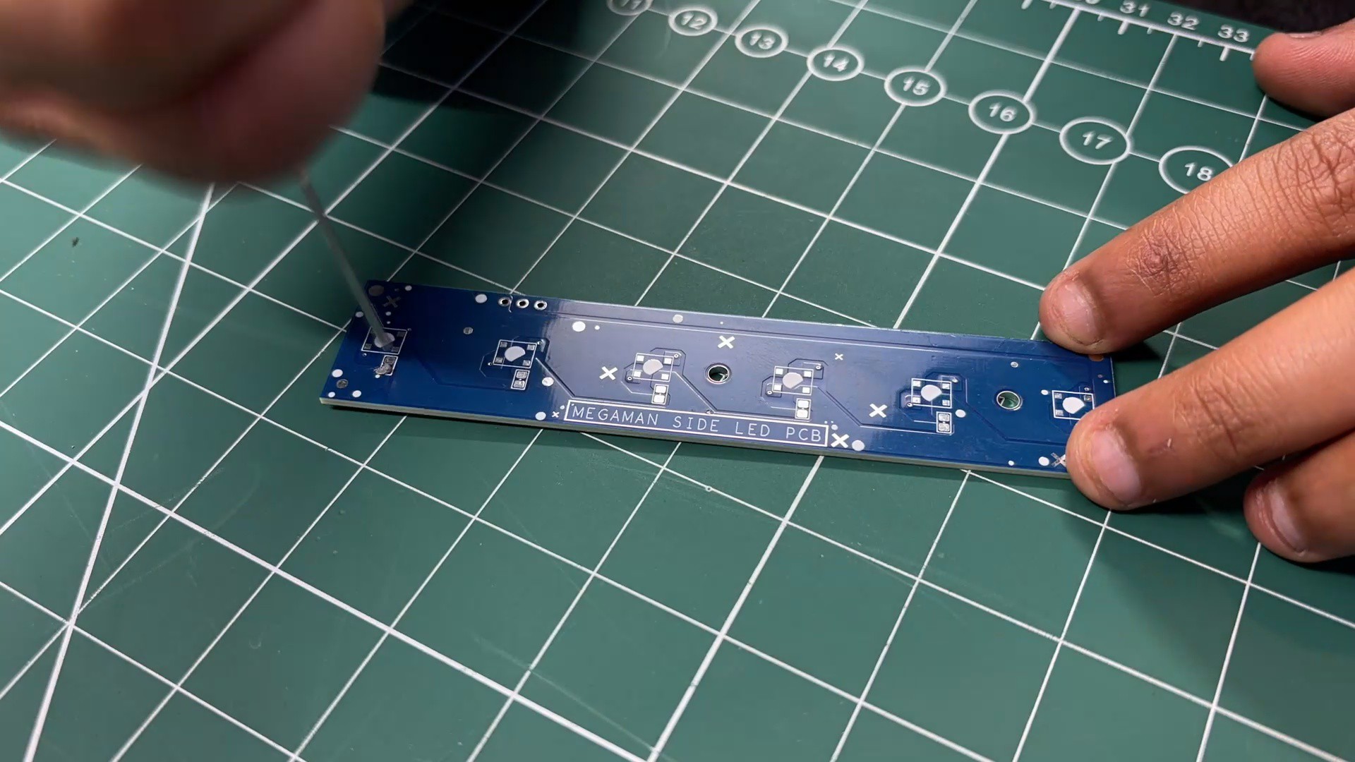
Next, we begin the assembly of the side power indicator LED board.
- Similar to the previously assembled PCBs, the process starts by applying solder paste to each SMD component pad on the board.
- Once the solder paste is applied, all SMD components are placed using tweezers. This includes six 100 nF capacitors in 0805 packages, followed by six WS2812B addressable LEDs, each positioned carefully in its designated footprint.
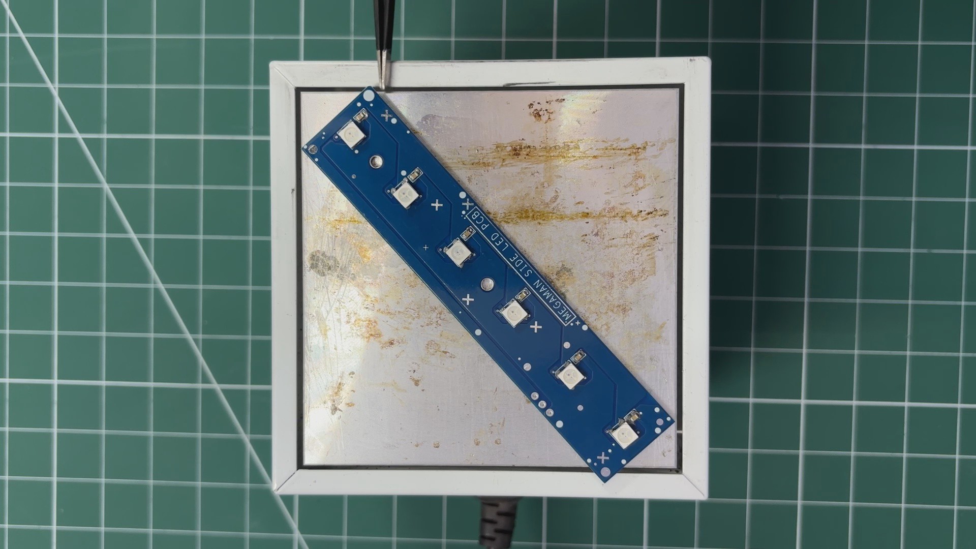
- After component placement, the PCB is transferred to a reflow hot plate. The board is heated until the solder paste reaches its melting temperature, allowing it to reflow and securely bond all components in place.
-
6MAIN ELECTRONICS SETUP
![]()
![]()
![]()
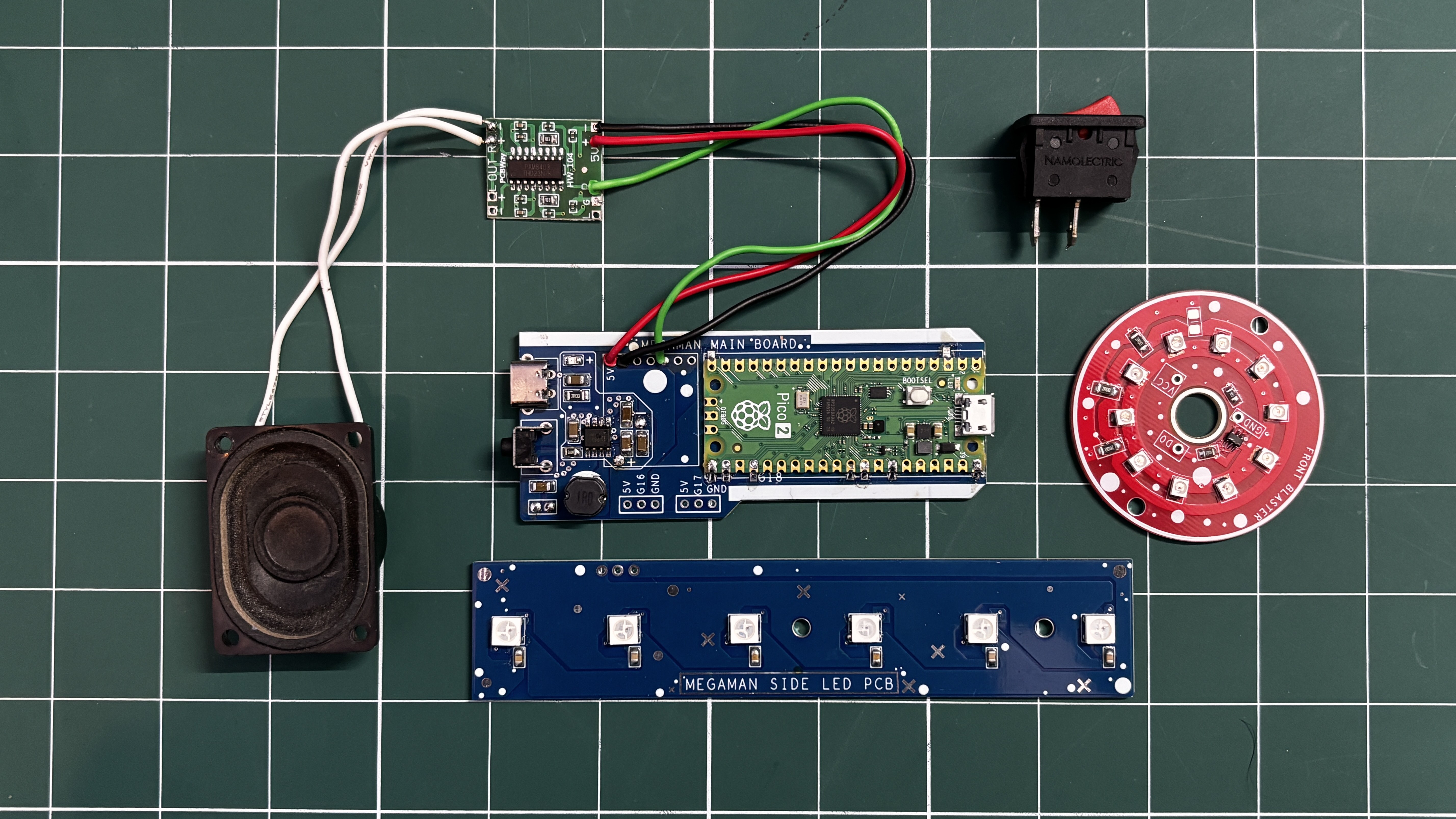
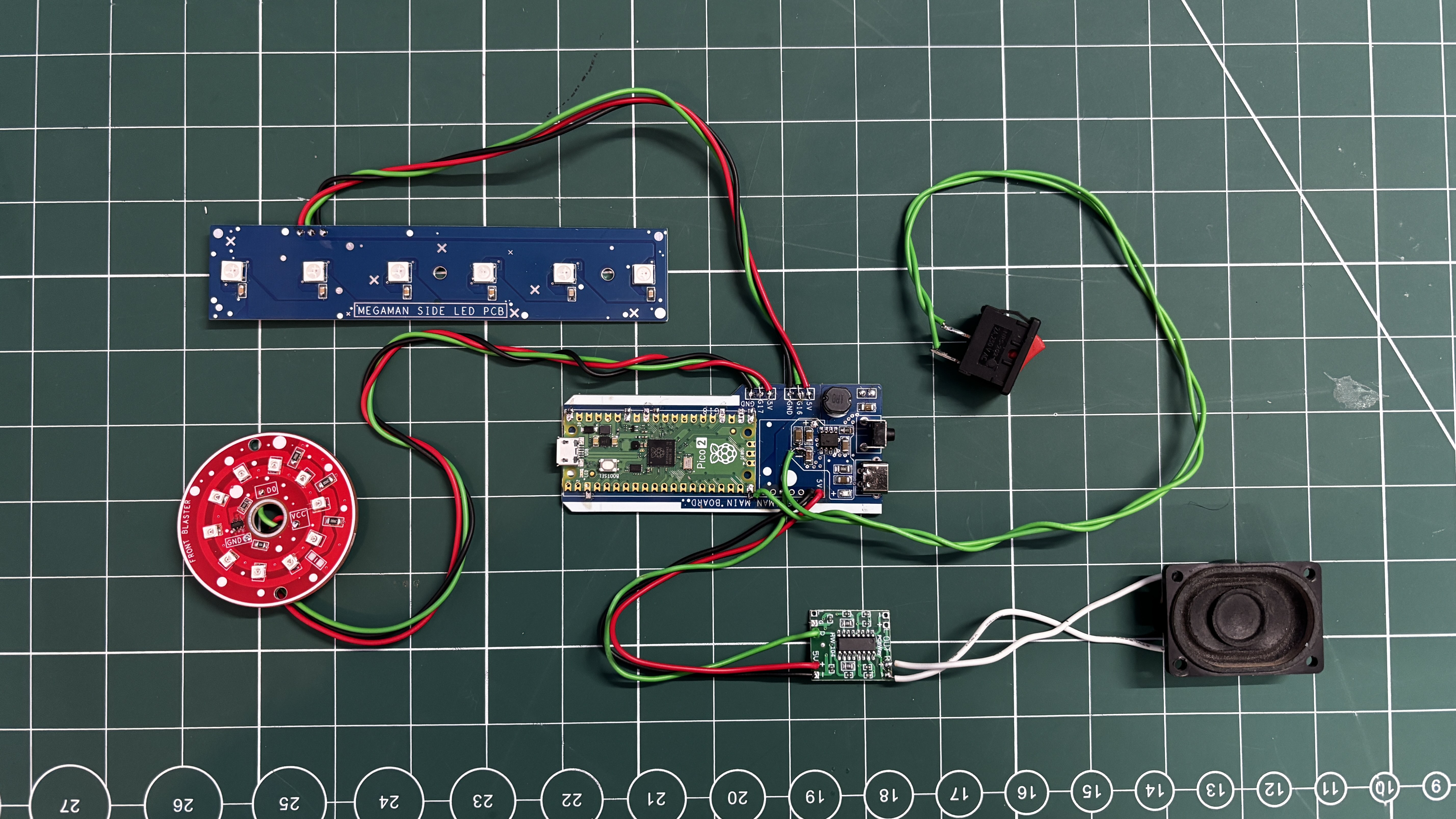
After finalizing all PCBs, we move on to the final wiring stage, where the front blaster PCB and the side power indicator LED board are connected to the main circuit.
Front Blaster PCB Connections
The front blaster PCB is wired to the main board as follows:
- VCC to 5V from the main circuit
- GND to GND of the main circuit
- DIN to GPIO17 of the Raspberry Pi Pico
Side Power Indicator LED Board Connections
Next, the side power indicator board is connected:
- VCC to 5V from the main circuit
- GND to Common ground
- DIN to GPIO16 of the Pico
Battery Connection
Once both LED boards are connected, the battery is reconnected to the main board:
- Battery positive to B+
- Battery negative to B—
Audio Amplifier Recap
The PAM8403 audio amplifier connections are as follows:
- GPIO26 to PAM8403 R input
- GND to GND
- VCC to 5V
Push Button Connection
The push switch is connected to control the firing action:
- One terminal of the switch to GPIO15
- Other terminal to GND
Pressing the switch pulls GPIO15 low, allowing the firmware to detect a button press.
Note: Although the switch looks like a regular rocker switch, it is actually a spring-loaded bell-type rocker switch, meaning it behaves like a momentary push button and returns to its default position when released.
-
7MAIN CODE
Here's the main code we prepared for our blaster, and it's a simple one.
#include <Adafruit_NeoPixel.h>
#define AUDIO_PIN    26
#define BUTTON_PIN   15
#define BLAST_LED    17
#define PIXEL_PIN    16
#define PIXEL_COUNT  6
#define MAX_CHARGE_TIME 3000
#define MAX_AMMO        6
#define COOLDOWN_TIME   10000
// Software volume control (percent)
#define AUDIO_VOLUME   60   // 100 = max, 60 = mid
// Front blast LED brightness cap (70%)
#define BLAST_LED_MAX  180  // ~70% of 255
// WS2812B colors
#define AMMO_YELLOW   strip.Color(255, 160, 0)
#define OVERHEAT_RED  strip.Color(255, 0, 0)
Adafruit_NeoPixel strip(PIXEL_COUNT, PIXEL_PIN, NEO_GRB + NEO_KHZ800);
int ammo = MAX_AMMO;
bool coolingDown = false;
void setup() {
pinMode(AUDIO_PIN, OUTPUT);
pinMode(BUTTON_PIN, INPUT_PULLUP);
pinMode(BLAST_LED, OUTPUT);
strip.begin();
strip.setBrightness(180);
strip.show();
randomSeed(analogRead(0));
refillAmmo();
}
void loop() {
if (coolingDown) return;
if (digitalRead(BUTTON_PIN) == LOW && ammo > 0) {
chargeAndFire();
ammo--;
updateAmmoBar();
if (ammo == 0) {
startCooldown();
}
}
}
// ================= CHARGE =================
void chargeAndFire() {
unsigned long startTime = millis();
unsigned long heldTime  = 0;
while (digitalRead(BUTTON_PIN) == LOW) {
heldTime = millis() - startTime;
if (heldTime > MAX_CHARGE_TIME) heldTime = MAX_CHARGE_TIME;
int chargeFreq = map(heldTime, 0, MAX_CHARGE_TIME, 300, 900);
tone(AUDIO_PIN, chargeFreq);
delay(15);
}
noTone(AUDIO_PIN);
fireBlast(heldTime);
}
// ================= BLAST =================
void fireBlast(unsigned long blastTime) {
if (blastTime < 120) blastTime = 120;
int startFreq = map(blastTime, 0, MAX_CHARGE_TIME, 900, 2400);
int step      = map(blastTime, 0, MAX_CHARGE_TIME, 25, 70);
unsigned long start = millis();
unsigned long gate  = 0;
while (millis() - start < blastTime) {
for (int f = startFreq; f > 300; f -= step) {
gate++;
if ((gate % 100) < AUDIO_VOLUME) {
tone(AUDIO_PIN, f);
} else {
noTone(AUDIO_PIN);
}
// Front LED aggressive flicker, capped at 70%
for (int i = 0; i < 3; i++) {
analogWrite(BLAST_LED, random(60, BLAST_LED_MAX));
delayMicroseconds(400);
}
delay(2);
}
}
noTone(AUDIO_PIN);
// Front LED cooldown (fade from 70% to off)
for (int i = BLAST_LED_MAX; i >= 0; i--) {
analogWrite(BLAST_LED, i);
delay(5);
}
}
// ================= AMMO BAR =================
void refillAmmo() {
ammo = MAX_AMMO;
for (int i = 0; i < PIXEL_COUNT; i++) {
strip.setPixelColor(i, AMMO_YELLOW);
}
strip.show();
}
void updateAmmoBar() {
for (int i = 0; i < PIXEL_COUNT; i++) {
if (i < ammo) {
strip.setPixelColor(i, AMMO_YELLOW);
} else {
strip.setPixelColor(i, 0);
}
}
strip.show();
}
// ================= COOLDOWN =================
void startCooldown() {
coolingDown = true;
unsigned long start = millis();
while (millis() - start < COOLDOWN_TIME) {
for (int i = 0; i < PIXEL_COUNT; i++) {
strip.setPixelColor(i, OVERHEAT_RED);
}
strip.show();
analogWrite(BLAST_LED, BLAST_LED_MAX);
delay(300);
strip.clear();
strip.show();
analogWrite(BLAST_LED, 0);
delay(300);
}
refillAmmo();
coolingDown = false;
}
In our sketch, we have only used one library, which is the Adafruit Neopixel Library; you need to install it before compiling the code.
#define AUDIO_PIN 26#define BUTTON_PIN 15#define BLAST_LED 17#define PIXEL_PIN 16#define PIXEL_COUNT 6
Audio Pin is the amplifier input pin, which we use GPIO26 for; Button Pin is GPIO15; Front Blaster Pin is GPIO17; and Neopixel Pin, or Side Power Board Din Pin, is connected to GPIO16, and we have also declared the Pixel Count, which is 6.
#define MAX_CHARGE_TIME 3000#define MAX_AMMO 6#define COOLDOWN_TIME 10000
Next we have the timing parameters, which include max charge duration (3 seconds), max ammo, which is a total of six shots before cooldown, and the cooldown timer, which is set to be 10 seconds. We can change the cooldown time to make the cooldown fast or slow by increasing or decreasing the time.
#define AUDIO_VOLUME 60#define BLAST_LED_MAX 180
Next are the audio and LED limits. These two are added to set the volume limit and LED brightness increase.
Again, these values can be increased or decreased.
#define AMMO_YELLOW strip.Color(255, 160, 0)#define OVERHEAT_RED strip.Color(255, 0, 0)
Next we defined the AMMO yellow color for the available ammo bar and the red color for when in overheating/cooldown mode.
Adafruit_NeoPixel strip(PIXEL_COUNT, PIXEL_PIN, NEO_GRB + NEO_KHZ800);int ammo = MAX_AMMO;bool coolingDown = false;
Using this section, WS2812B LEDs are initialized. ammo tracks remaining ammo shots, and cooldown blocks input during cooldown.
void setup() {pinMode(AUDIO_PIN, OUTPUT);pinMode(BUTTON_PIN, INPUT_PULLUP);pinMode(BLAST_LED, OUTPUT);strip.begin();strip.setBrightness(180);strip.show();randomSeed(analogRead(0));refillAmmo();}This is the setup function; we added general things in the function, like GPIO configuration, initializing LEDs, etc., but the main part in this is the seeds' randomness for natural flicker and filling the ammo bar at startup.
void loop() {if (coolingDown) return;if (digitalRead(BUTTON_PIN) == LOW && ammo > 0) {chargeAndFire();ammo--;updateAmmoBar();if (ammo == 0) {startCooldown();}}}Next is our loop function, which ignores all input during cooldown. starts charging when the trigger is pressed and fires on release; it also reduces ammo and updates the LED bar and triggers cooldown when ammo reaches zero.
void chargeAndFire()
This function measures how long the trigger is held; it generates a rising audio tone during charging, it also caps charge time to prevent overcharging, and it calls the firing routine when the button is released. Basically, the longer the press, the higher the charge.
void fireBlast(unsigned long blastTime)
This function controls plasma-like descending audio tones along with aggressive front LED flickering and then smooth LED fade-out after firing. Here the blast duration scales with charge time, closely mimicking Mega Man-style behavior.
void refillAmmo()void updateAmmoBar()
Each WS2812B LED represents one ammo unit; LEDs turn off as ammo is consumed, and all LEDs turn back on after cooldown.
void startCooldown()
When ammo is depleted, the side LEDs blink red and the front blaster LED pulses; input is ignored for 10 seconds.
-
8FRONT SECTION ASSEMBLY
![]()
![]()
![]()
![]()
- The front section assembly process begins by adding the front blaster PCB into position by aligning the mounting holes of the PCB with the screw holes on the body. We use M2 screws to secure the PCB to the body.
- The wires of the PCB are passed through the hole provided in the body from the back side.
-
9MAIN BODY & SIDE POWER LED ASSEMBLY
![]()
![]()
![]()
![]()
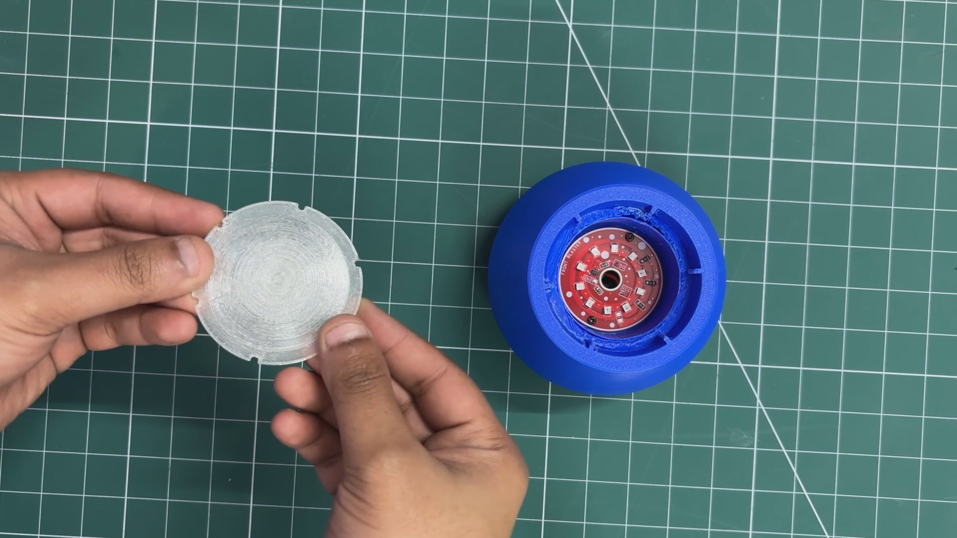
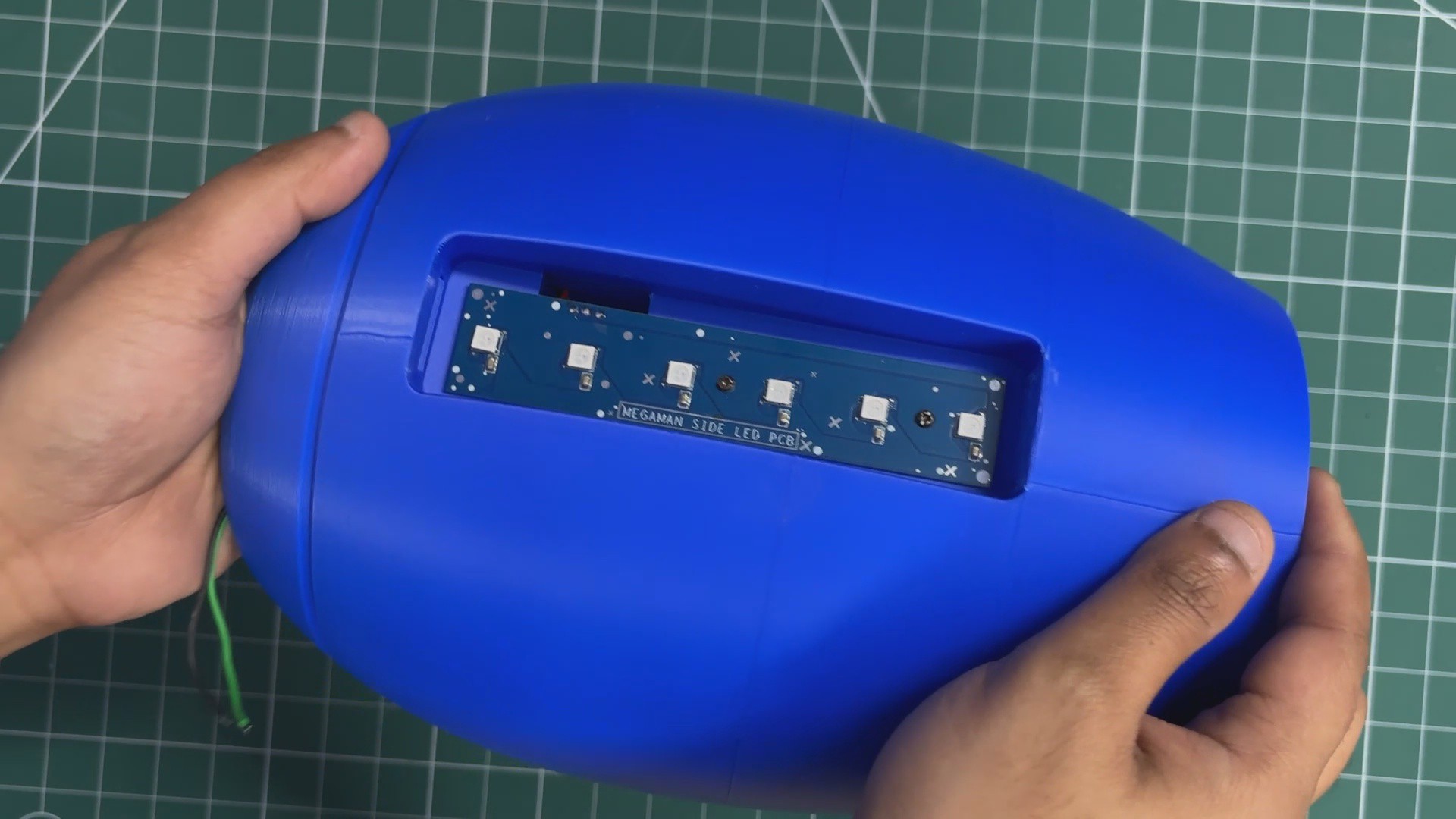
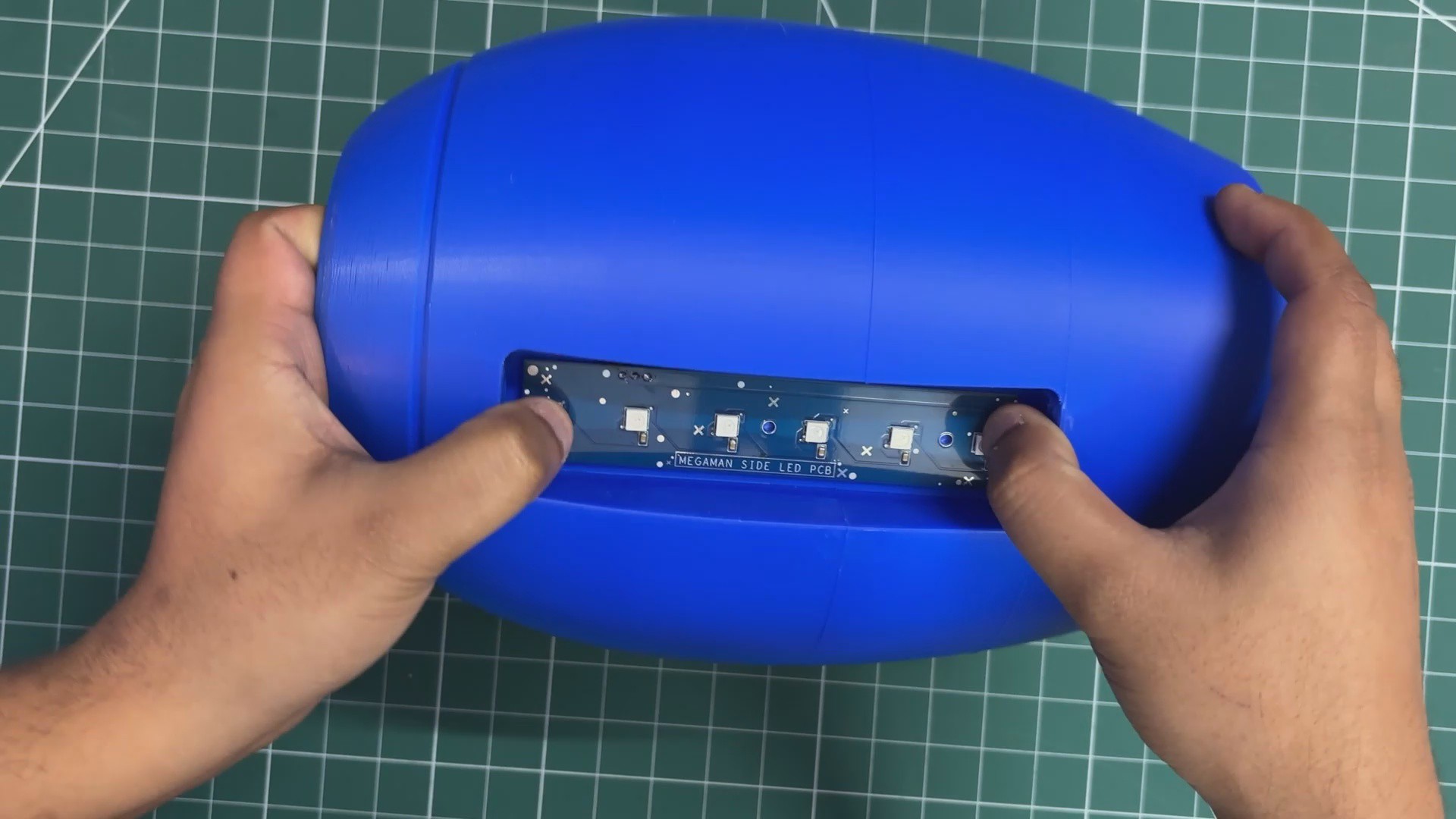
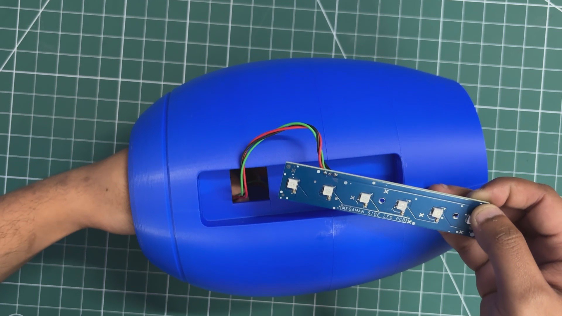
- We now begin with the side power LED assembly with the main body. We add the side power PCB into position by matching its mounting holes with the screw holes provided on the body. We then use two M2 screws to secure both together.
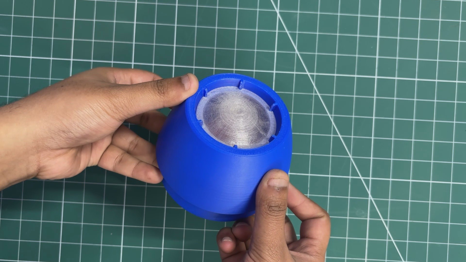
- Over the PCB, we place the diffuser part, which is pressure-fitted into position. On both sides of the diffuser, we have added snap locks, and when the diffuser is pushed into place, these locks allow it to get securely fixed in position.
- Additionally, to increase the effect of the bar LED, we created a grid-like part that sits inside the diffuser to isolate each LED’s glow. This part ensures that light from each LED falls only on the top side of the diffuser and does not interfere with the left and right sides.
-
10BODY ASSEMBLY
![]()
![]()
![]()
![]()
![]()
- The body assembly process begins by placing the front section assembly onto the main body. The front section is pressure-fitted into position, ensuring a secure fit.
- Next, the handgrip is installed from the bottom side of the main body. The grip is slid into place and then secured using four M2 screws, firmly fixing it to the main body and completing the structural assembly.
Mega Man's Mega Buster
Full-Size Working Replica of Mega Man's Mega Buster


Discussions
Become a Hackaday.io Member
Create an account to leave a comment. Already have an account? Log In.