Close
0%
0%

Portable Studio Light

Studio Light Mini lets you pick colors and control RGB lights easily through a web app. Just tap, set, and glow.

Similar projects worth following
Greetings everyone and welcome back. Here's something super bright.

The Portable Studio Light is an ultra-compact RGB lighting solution intended to improve video production and visual aesthetics. With a sleek 3D-printed housing and a custom-engineered lens, it diffuses brilliant light from just four WS2812B LEDs.

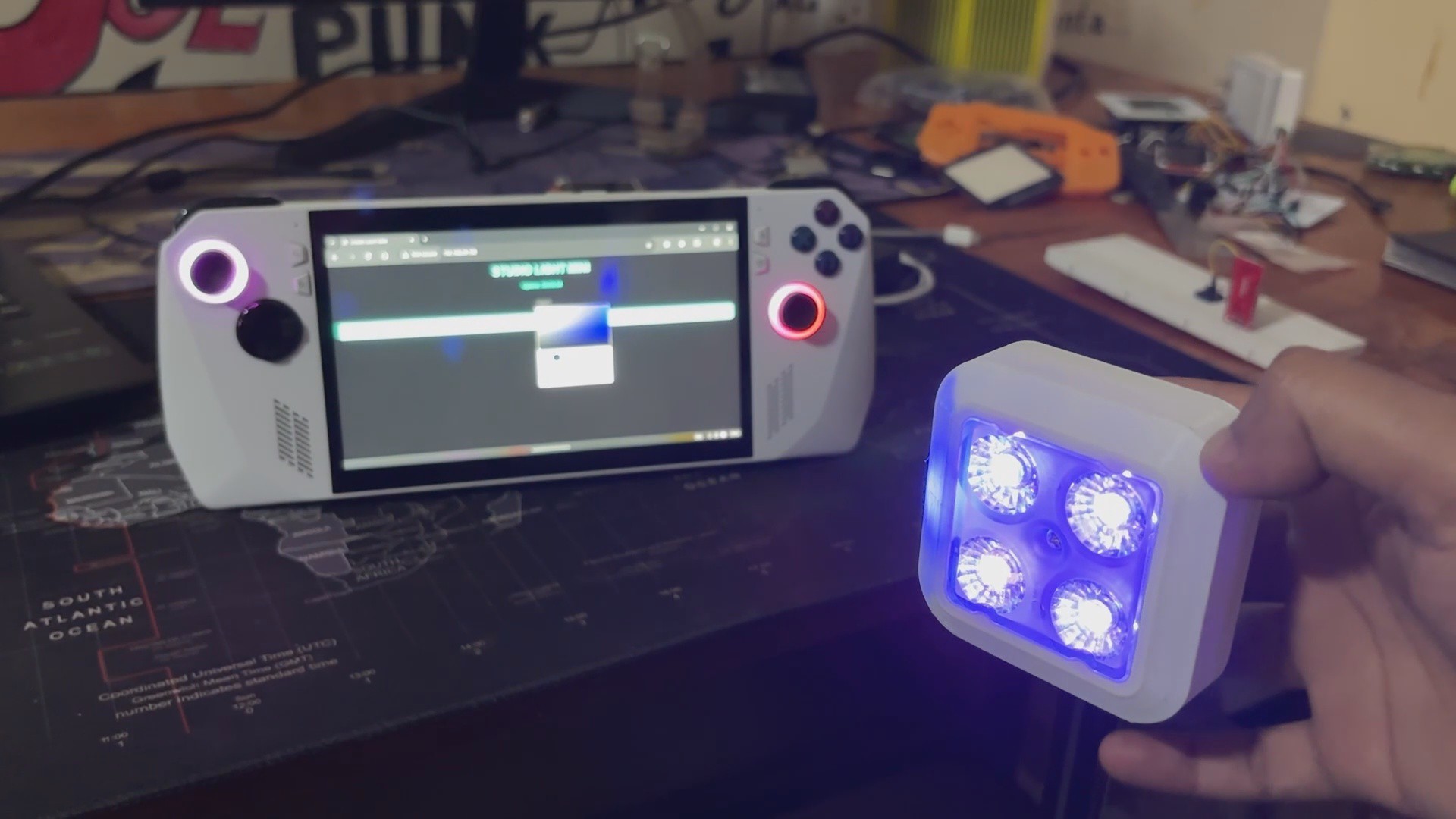
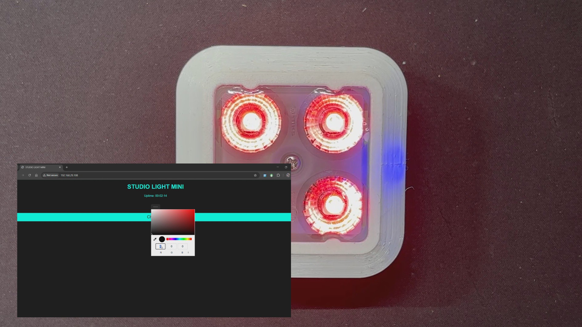
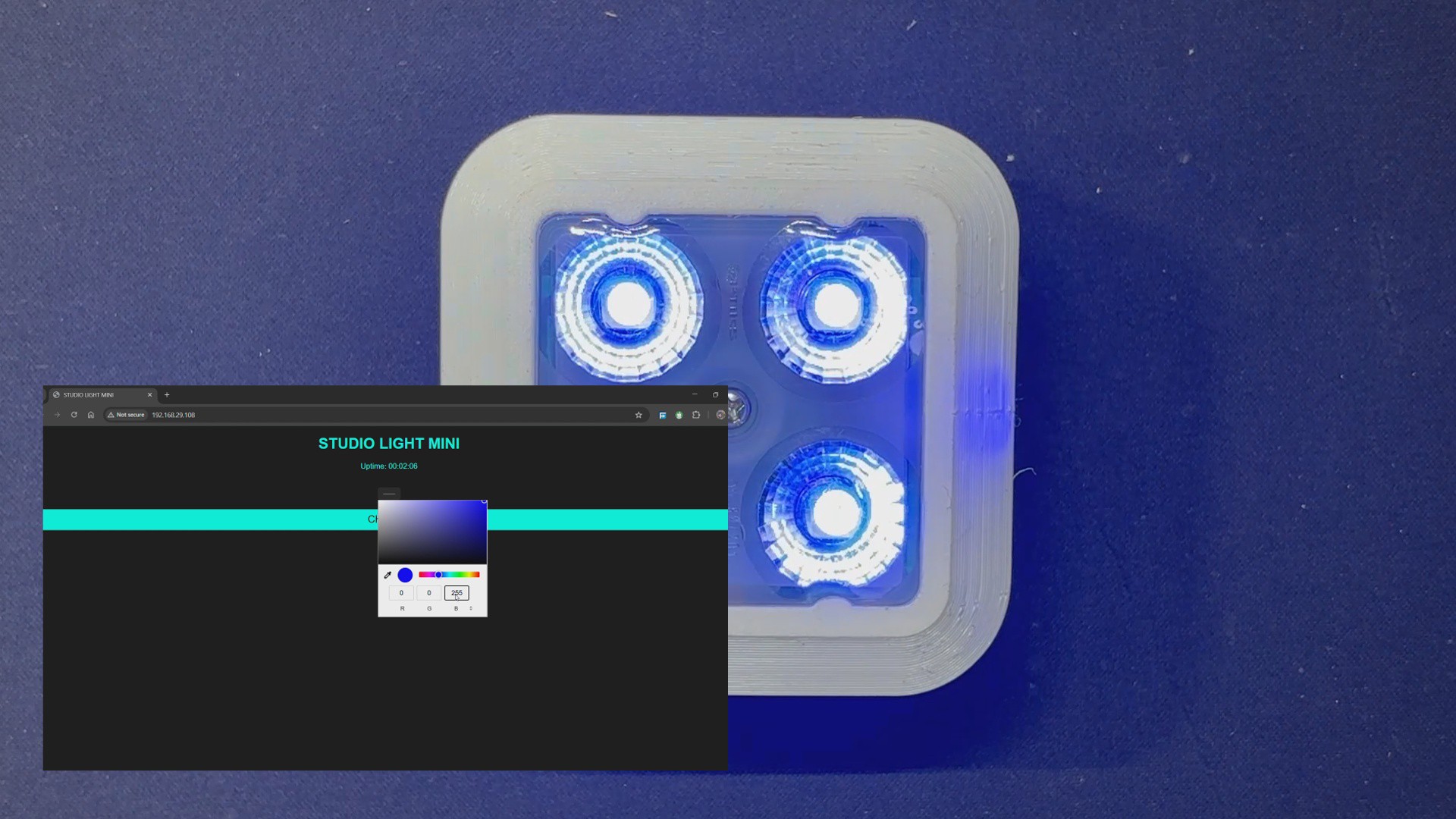
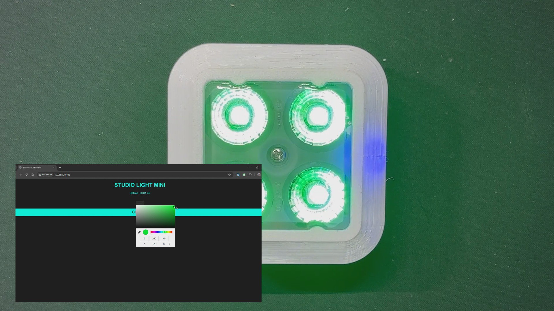
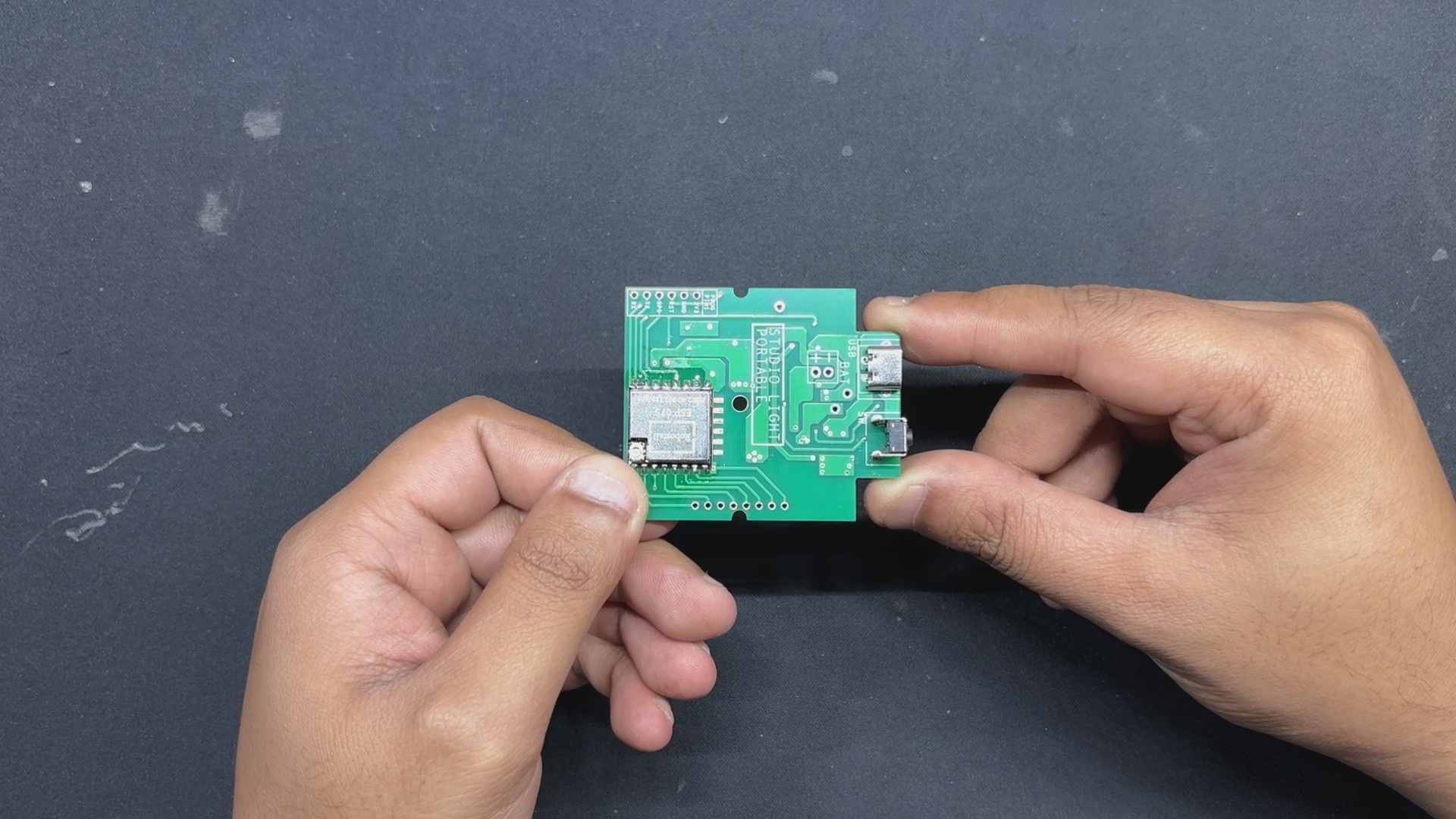
The Studio light, powered by an ESP8266 microcontroller, links smoothly to a browser-based web app, allowing for exact color choices and dynamic control directly from your phone or laptop.

The Portable Studio Light was created to address an actual problem: I just relocated and found myself frequently hopping between two workplaces. I needed a lighting setup that was portable, easy to mount anyplace, and strong enough to enhance my video output.

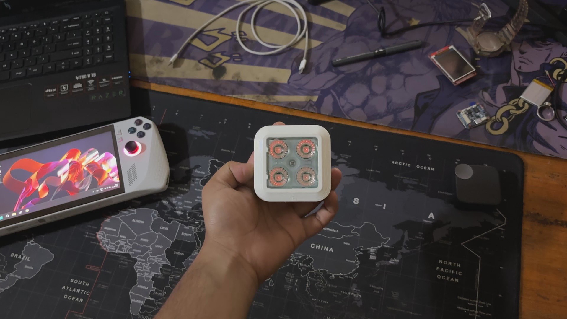
Our Setup is powered by an ESP8266, with a custom 3D-printed lens and enclosure to make the most of only four WS2812B LEDs. The web app is where the magic happens: it's simple, responsive, and works on any device. I've used my phone, laptop, and ROG Ally to control it. Simply select a hue and it refreshes instantaneously, allowing us complete creative freedom no matter where I am working.

Previous Build

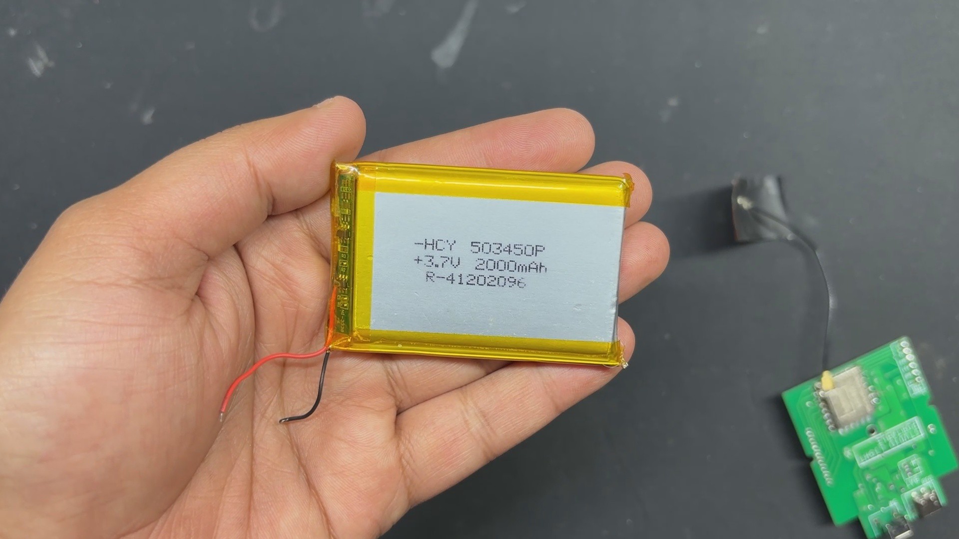
previously, I created a similar Studio light that was far bigger and more powerful in terms of both light and battery capacity. In the initial version, I used two PCBs connected by a 3D printed bracket and a long PCB standoff. The two PCBs consisted of an LED board and a control board. The LED board contains all of the non-addressable SMD RGB 5050 LEDs, including Warm White and Cool White LEDs.

The Control board included a PICO 2 with a display, a few buttons, an integrated power source, and two 8205S Mosfets as a switch setup that we linked to the LED board to turn on and off the Warm and Cool white LEDs.

One major issue with the project was its size, and I chose to use the WS2811 chip instead of an RGB addressable LED. I connected more than ten LEDs in parallel with the WS2811 IC, but the maximum current the WS2811 can sustain is roughly 20 mA per channel, causing all LEDs to flash very dimly in all R G and B modes.

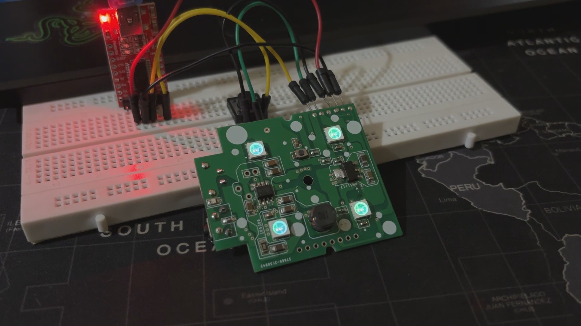
The new portable version resolved the current issue by replacing the WS2811 IC with higher-quality WS2812B LEDs.

You can check out the previous project from here—

https://www.hackster.io/Arnov_Sharma_makes/pico-studio-light-4eac11

3D Design

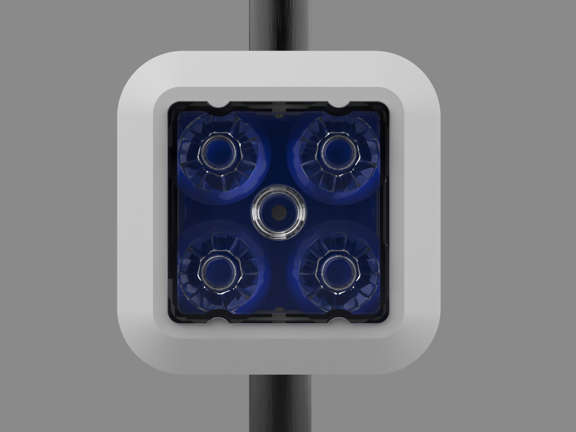
The 3D design of this project began with creating a proper-sized model of the lens that will be used in this build. The idea here was to place a PCB on the backside of the lens and then create an enclosure around it to house the batteries and electronics. The entire device will have a Stand Holder component that will be used to attach the device to any tripod or pipe.

The enclosure was designed in two halves: the front body and the lid section.

The front body has a huge opening in its center where the lens will be secured. The circuit was then modeled and connected to the lens, which is kept in place by a hole in the middle into which we will insert an M2.5 nut and bolt.

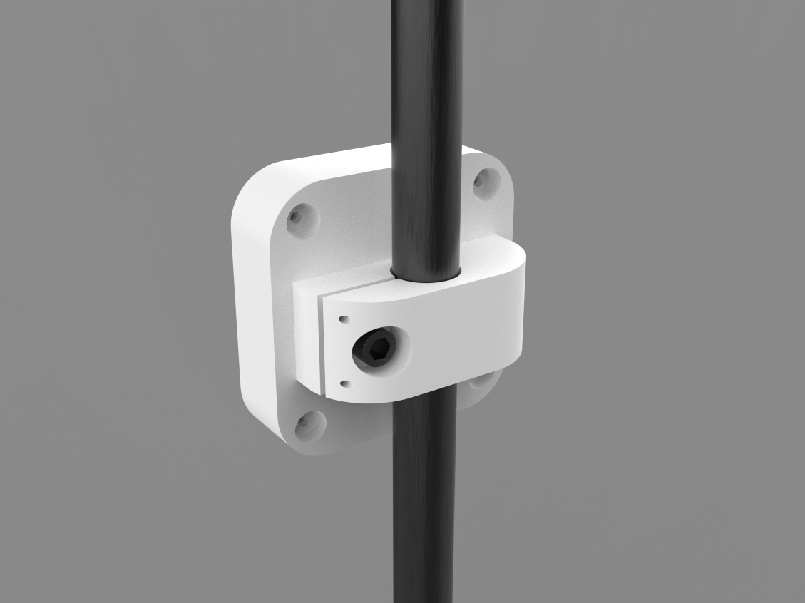
The lid is attached to the front body from the back and held in place with four M2 screws. The Lid Part also houses the Stand Holder Part.

We have created a 20mm DIA hole on the Stand Holder for attaching a tripod with this arrangement. We also constructed a slit and provided a hole and slot for installing an M6 nut and bolt; by tightening these nuts and bolts, the 20mm dia. hole size drops to 19.5 or less, allowing our device to be fastened securely with a tripod.

After preparing the 3D model, we exported the mesh files for all of the parts and 3D printed them on our K10 Max 3D printer with white Hyper PLA.

PCB Design

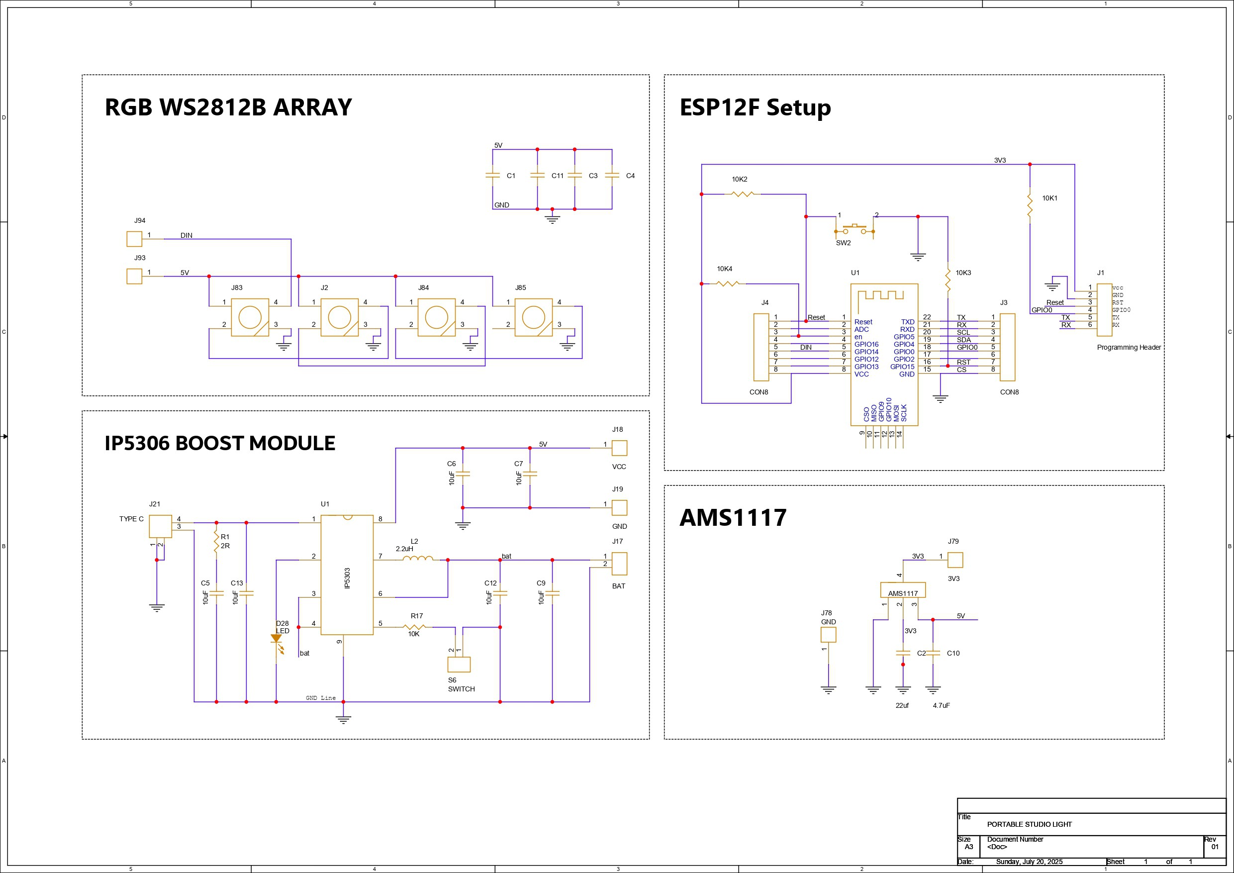
Let's have a look at the schematic for this project, which is divided into four primary parts, one of which is the microcontroller section, which in our case is the ESP12F setup. Here, we've connected the ESP12F module to a few 10K resistors in the minimal configuration required for the ESP12F to work. We also included a CON6 Header pin connector that connects to the TX, RX, GPIO 0, RESET, VCC, and GND pins of the ESP12F Module; this connector will be used to flash the ESP chip using a UART adapter.

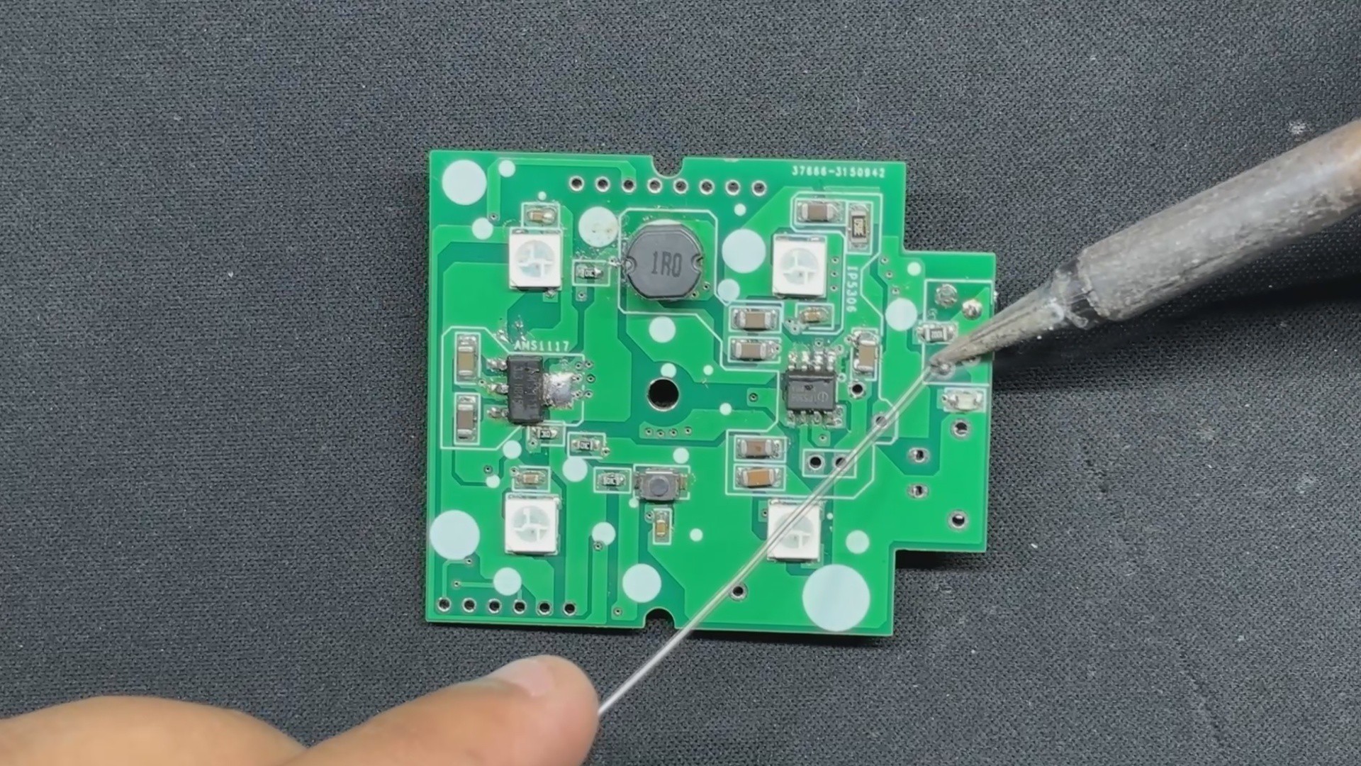
Next, we have the Power source section, which is the IP5306 Power management IC Setup, which we have previously used in...

Read more »

PORTABLE STUDIO LIGHT v6.step

step - 1.58 MB - 07/21/2025 at 17:53

Download

TOP.3mf

3mf - 136.26 kB - 07/21/2025 at 17:53

Download

LID.3mf

3mf - 86.69 kB - 07/21/2025 at 17:53

Download

HOLDER.3mf

3mf - 94.56 kB - 07/21/2025 at 17:53

Download

  • 1
    PCB ASSEMBLY
    • The PCB assembly process begins by applying solder paste to each SMD component pad one at a time with a solder paste dispensing needle; we are using 63/37 Sn/Pb solder paste here.
    • Next, we use an ESD tweezer to choose and arrange all SMD components on the top side of the board.
    • We pick the circuit and place it on the Reflow hotplate, which heats the PCB to the solder paste melting temperature, causing all SMD components to permanently solder to their pads.
    • Next, we begin assembly on the bottom side of the board, beginning with the placement of the ESP12F Module.
    • Because we are soldering on the other side of the board, we must use a soldering iron. We begin by soldering the first pad of the ESP model, which secures it in place and allows us to begin soldering the pins.
    • Now come the through-hole components; we begin by installing the Push Switch, followed by the type C Port.
  • 2
    Flashing the ESP12F

    Next is the Flashing process of the main circuit's ESP12F Module.

    The usual FTDI board method, which requires connecting a flashing button between GPIO 0 and the GND Port, is being used to program the ESP12F Module. During uploading, the ESP12F enters programming mode by long pressing the Flash button first, followed by the reset button.

    Here's an article about programming ESP12F with FTDI Board for more details:

    https://www.hackster.io/Arnov_Sharma_makes/esp12f-standalone-circuit-1de4a7

    Here's the code that was used in this project and it's a simple one.

    #include <Adafruit_NeoPixel.h>
    #include <ESP8266WiFi.h>
    #include <ESP8266WebServer.h>
    #include <ESP8266mDNS.h>
    // WiFi credentials
    const char* ssid = "URSSID";
    const char* password = "URPASS";
    // Web server
    ESP8266WebServer server(80);
    // NeoPixel setup
    #define NeoPIN 14
    #define NUM_LEDS 4
    int brightness = 250;
    //Use GRB ordering for WS2812B
    Adafruit_NeoPixel strip = Adafruit_NeoPixel(NUM_LEDS, NeoPIN, NEO_GRB + NEO_KHZ800);
    const int led = 13;
    void setup() {
    Serial.begin(115200);
    strip.setBrightness(brightness);
    strip.begin();
    strip.show();
    delay(10);
    Serial.println("NeoPixel initialized");
    pinMode(led, OUTPUT);
    digitalWrite(led, LOW);
    WiFi.begin(ssid, password);
    Serial.print("Connecting to WiFi: ");
    Serial.println(ssid);
    while (WiFi.status() != WL_CONNECTED) {
    delay(500);
    Serial.print(".");
    }
    Serial.println();
    Serial.print("Connected to: ");
    Serial.println(ssid);
    Serial.print("Web App IP Address: ");
    Serial.println(WiFi.localIP().toString());
    if (MDNS.begin("esp8266")) {
    Serial.println("MDNS responder started");
    }
    server.on("/", handleRoot);
    server.onNotFound(handleNotFound);
    server.begin();
    Serial.println("HTTP server started");
    }
    void loop() {
    server.handleClient();
    }
    void handleRoot() {
    digitalWrite(led, HIGH);
    String color = server.arg("c");
    if (color.length() == 7 && color[0] == '#') {
    setNeoColor(color);
    }
    int sec = millis() / 1000;
    int min = sec / 60;
    int hr = min / 60;
    char clr[7] = "FFFFFF";
    if (color.length() == 7) {
    color.toCharArray(clr, 7);
    }
    // Reduced buffer size for safety
    char webpage[1200];
    snprintf(webpage, sizeof(webpage),
    "<!DOCTYPE html>\n<html>\n\
    <head>\n\
    <title>STUDIO LIGHT MINI</title>\n\
    <meta name='viewport' content='width=device-width, initial-scale=1.0'>\n\
    <style>\n\
    body { background-color:#111; color:#00ffe7; font-family:Arial; text-align:center; margin:0; padding:0; }\n\
    h1 { margin-top:20px; font-size:2em; }\n\
    input[type=color] { margin-top:20px; padding:10px; border:none; border-radius:6px; background:#222; color:#fff; }\n\
    .btn { font-size:16pt; margin:20px; padding:10px 20px; background:#00ffe7; color:#111; border-radius:8px; cursor:pointer; }\n\
    .btn:hover { background:#00ccbb; }\n\
    </style>\n\
    </head>\n\
    <body>\n\
    <h1>STUDIO LIGHT MINI</h1>\n\
    <p>Uptime: %02d:%02d:%02d</p>\n\
    <form method='post'>\n\
    <input type='color' name='c' value='#%s' onchange='this.form.submit();'>\n\
    <div class='btn' onclick='this.closest(\"form\").submit();'>CHANGE</div>\n\
    </form>\n\
    </body>\n</html>",
    hr, min % 60, sec % 60, clr);
    server.send(200, "text/html", webpage);
    digitalWrite(led, LOW);
    }
    void handleNotFound() {
    digitalWrite(led, HIGH);
    String message = "File Not Found\n\n";
    message += String("URI: ") + server.uri() + "\n";
    message += String("Method: ") + (server.method() == HTTP_GET ? "GET" : "POST") + "\n";
    message += "Arguments: " + String(server.args()) + "\n";
    for (uint8_t i = 0; i < server.args(); i++) {
    message += " " + server.argName(i) + ": " + server.arg(i) + "\n";
    }
    server.send(404, "text/plain", message);
    digitalWrite(led, LOW);
    }
    void setNeoColor(String value) {
    int number = (int) strtol(&value[1], NULL, 16);
    int r = number >> 16;
    int g = number >> 8 & 0xFF;
    int b = number & 0xFF;
    Serial.printf("RGB: %d %d %d\n", r, g, b);
    //Send colors as GRB, matching hardware expectations
    for (int i = 0; i < NUM_LEDS; i++) {
    strip.setPixelColor(i, strip.Color(g, r, b));
    }
    strip.show();
    delay(10);
    Serial.println("Color updated.");
    }
  • 3
    Power Source

    This project's power source is a 3.7V 2000mAh LiPo cell. We begin the power source assembly process by connecting the Lipo cell's positive and negative terminals to the Battery CON2 port of the IP5306 IC.

    We plug a type C charger into our circuit, and the blue lights begin to flash, indicating that this setup is functional. When the blinking becomes stable, the battery has been fully charged.

View all 7 instructions

Enjoy this project?

Share

Discussions

Similar Projects

Does this project spark your interest?

Become a member to follow this project and never miss any updates