 Next Builder
-
1CAD & 3D Printing
![]()
![]()
![]()
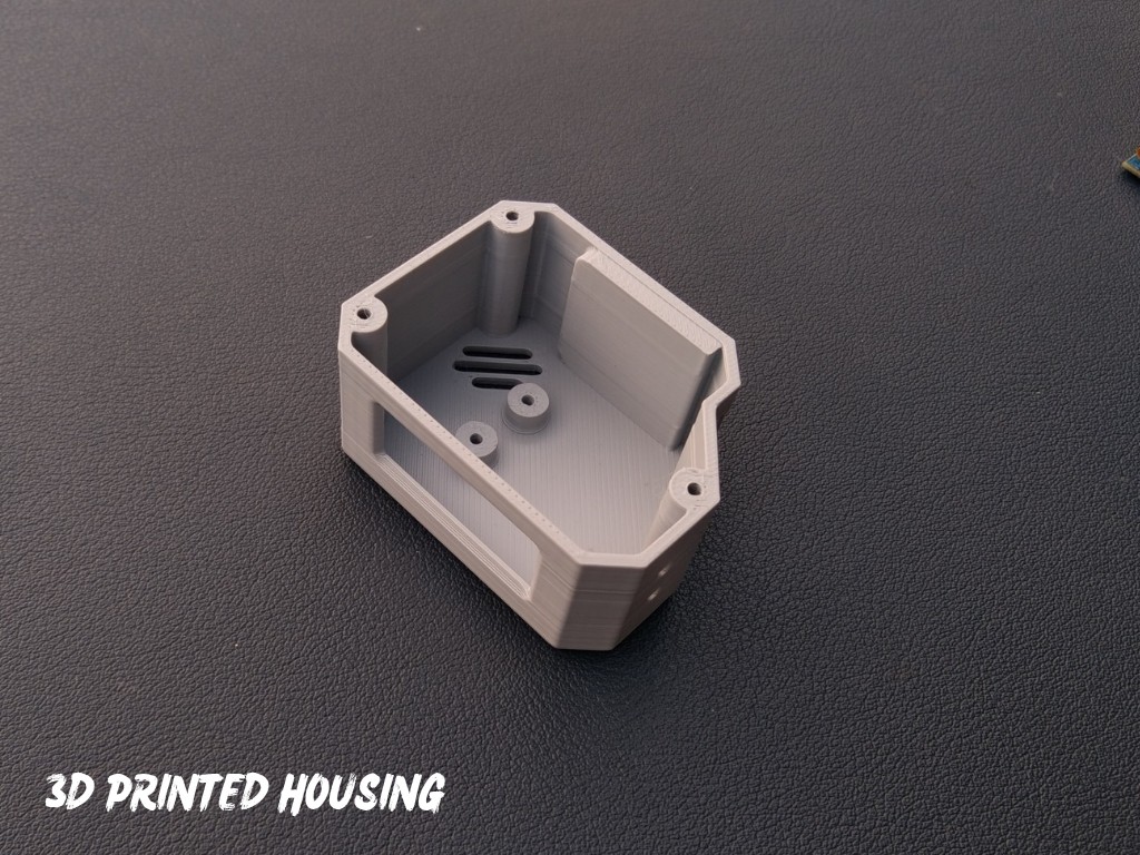
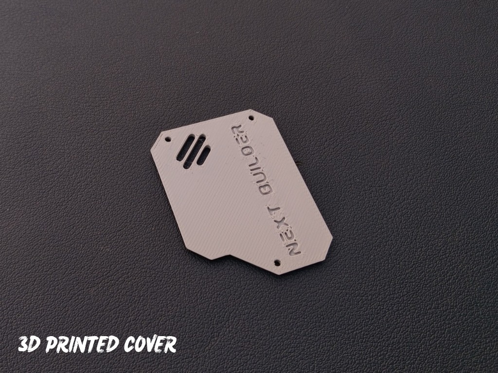
To begin this project, I designed the OrbitClock in Autodesk Fusion 360, carefully keeping all the component dimensions and aesthetics in mind. My goal was to make it small, futuristic, and easy to assemble, just like a real mini satellite.
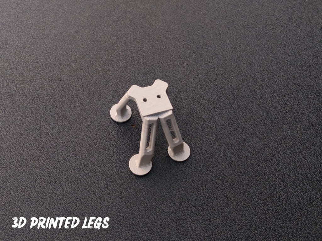
The design features a clean body with a front display window, cooling vents, and landing-style legs that give it a true space-inspired look. It’s also 3D-printing friendly, requiring no complex supports or post-processing. You can easily view or edit the CAD model using the Fusion 360 web viewer, and feel free to customize the design to match your own style or components.
For 3D Printing, You can directly download the required STL files below:
- Housing.stl
- Cover.stl
- Legs.stl
-
2Display Assembly
![]()
![]()
![]()
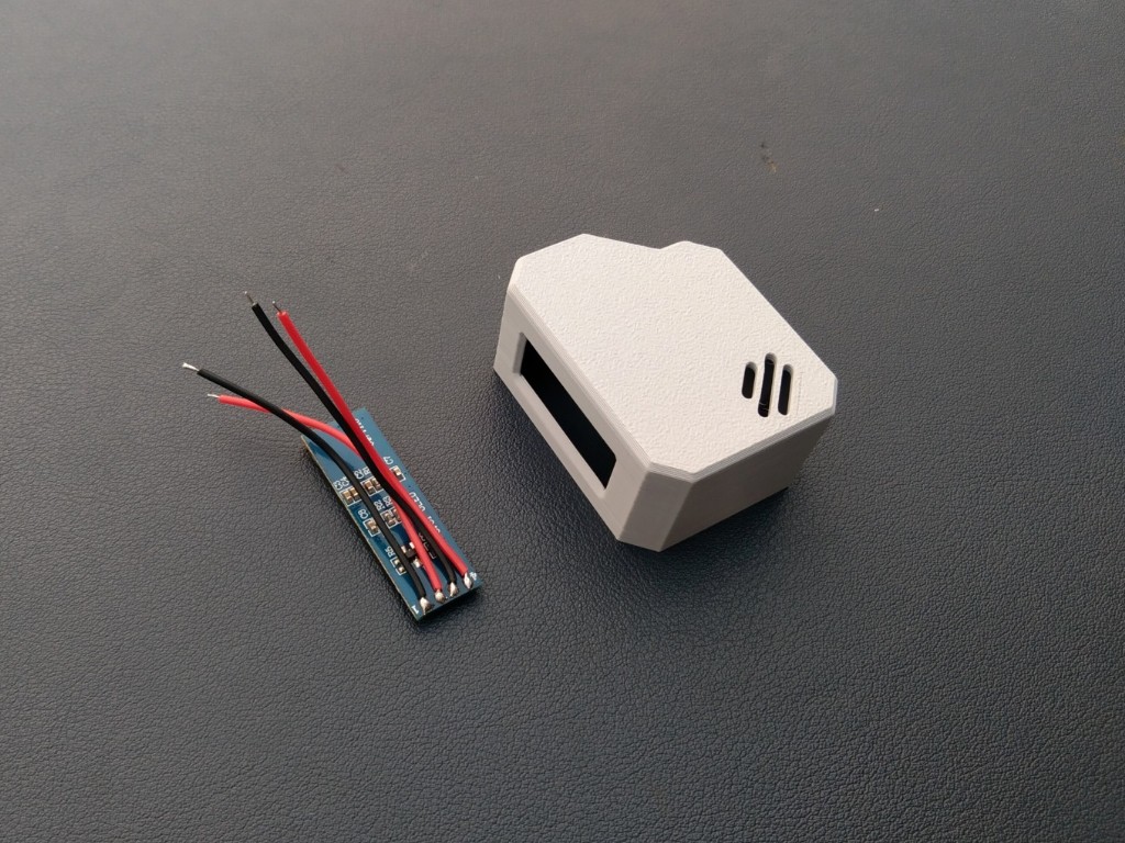
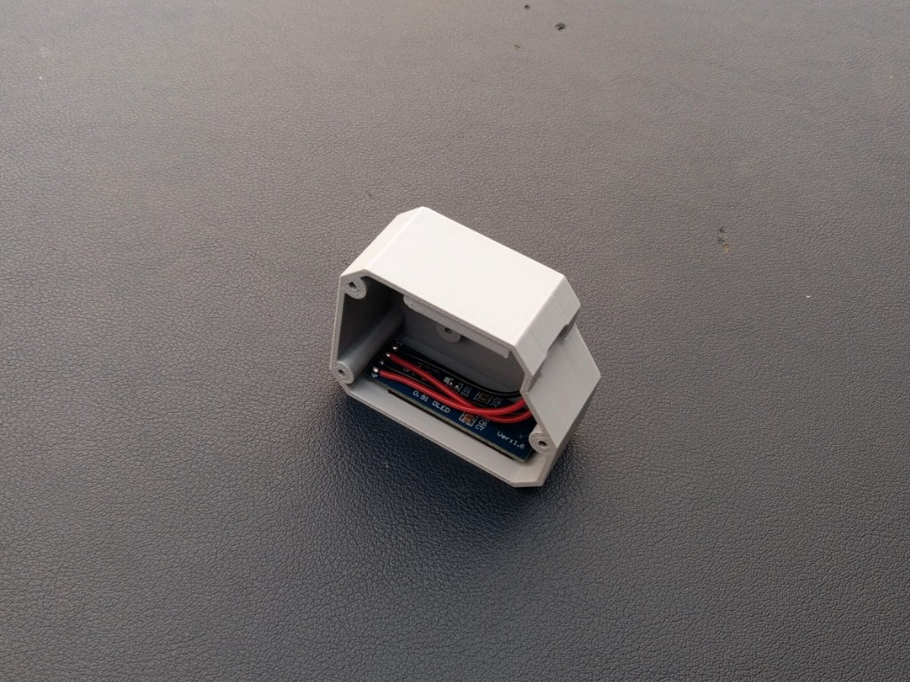
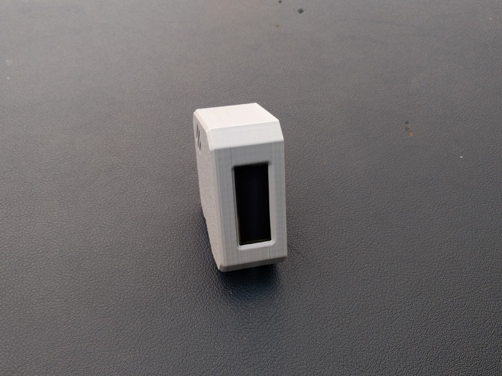
Let’s start by assembling the OLED display into the 3D-printed housing. Before placing it inside, I soldered four wires to the display pins — VCC, GND, SCL, and SDA — so that connecting it to the microcontroller later becomes quick and easy.
Once the wires were attached, I applied a tiny amount of super glue along the edges of the display and carefully fixed it into the dedicated display slot on the front panel. Make sure it’s aligned properly and sits flat for a clean look.
-
3Microcontroller Assembly
![]()
![]()
![]()
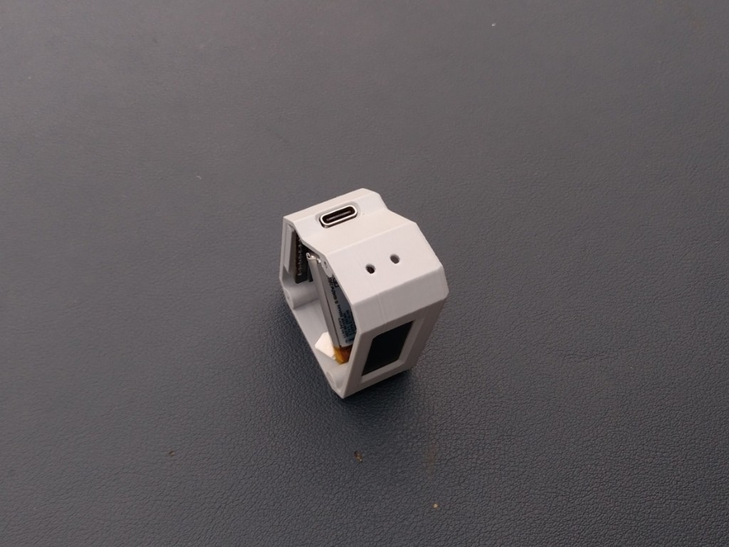
After completing the display assembly, it’s time to mount the Beetle ESP32-C3 microcontroller. Apply a small amount of super glue on the back side of the board and carefully place it in its dedicated slot inside the enclosure.
Make sure the Type-C port is perfectly aligned with the opening on the case so that you can easily connect the cable later. Hold it in place for a few seconds until the glue sets properly.
-
4Sensor Assembly
![]()
![]()
![]()
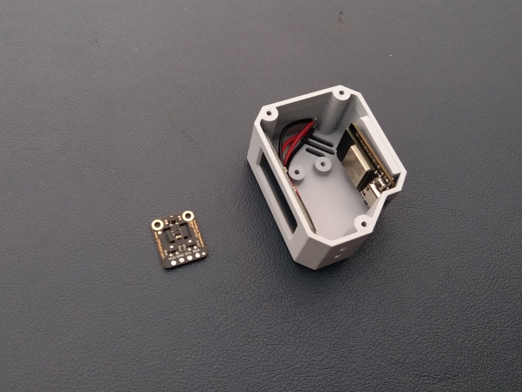
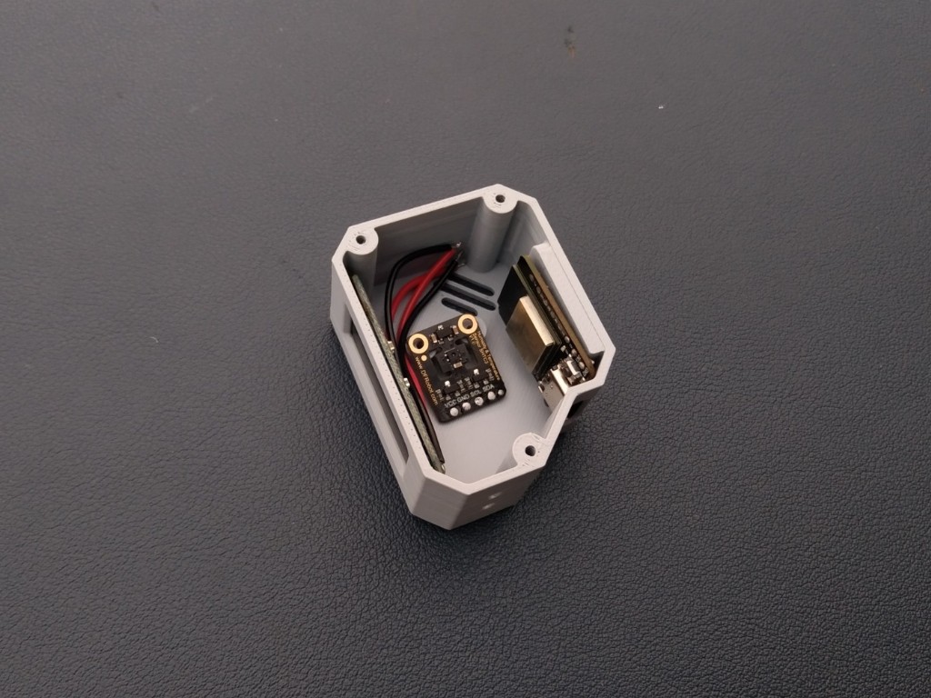
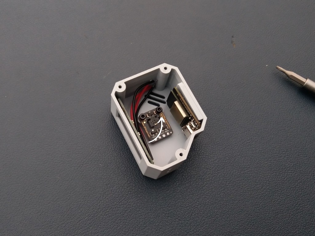
Once the microcontroller is in place, it’s time to install the final main component — the SHTC3 Temperature and Humidity Sensor. Carefully position the sensor in its dedicated slot inside the enclosure. Use two small M3 screws to secure it firmly with the help of a screwdriver. Make sure the sensor is properly aligned and tight enough so it stays fixed during use.
-
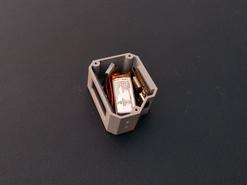
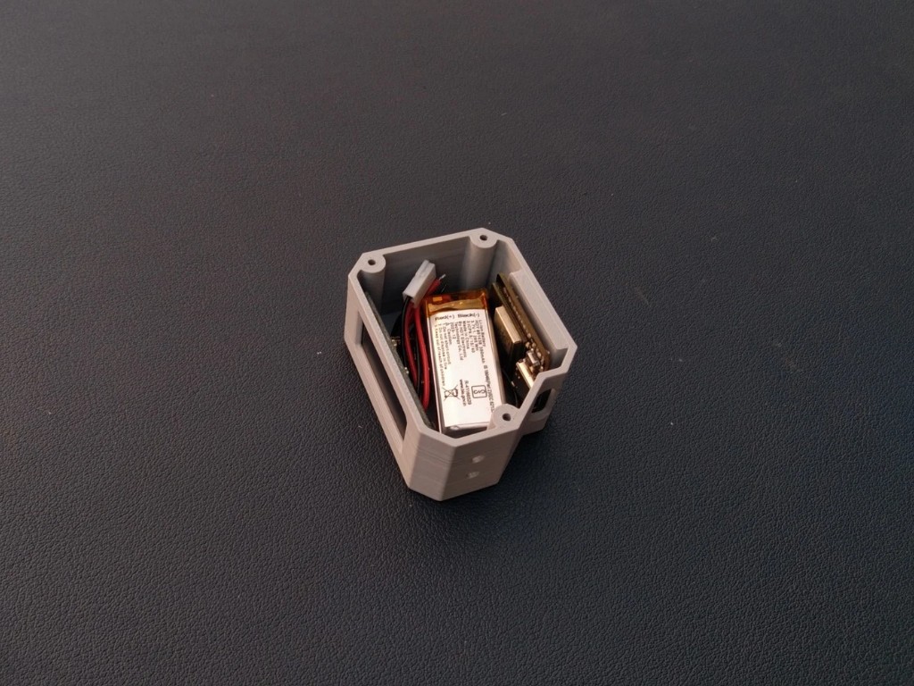
5Battery Assembly
![]()
![]()
![]()
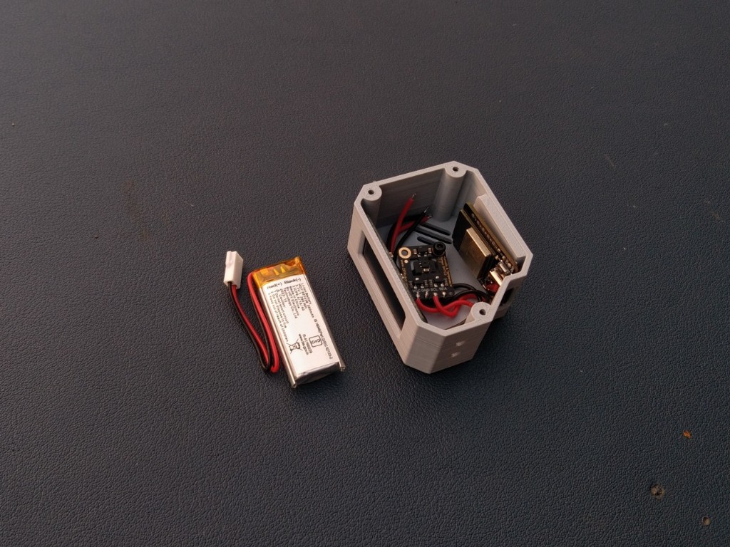
This step is optional — if you want to make your Orbit Clock portable and rechargeable, you can add the Li-Po battery; otherwise, it will also work perfectly when powered via USB.
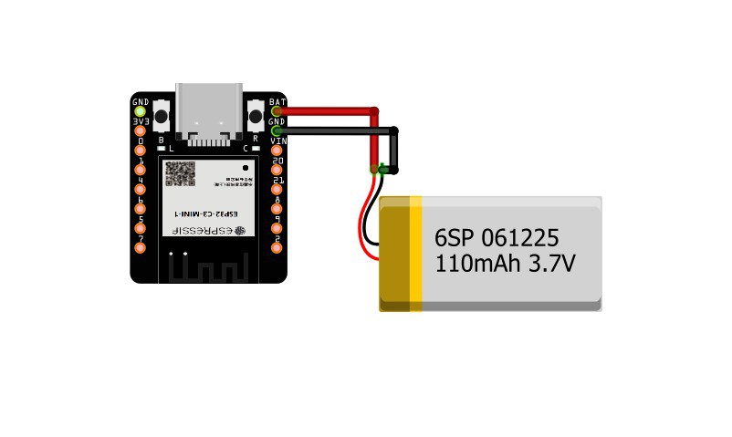
One great feature of the Beetle ESP32-C3 is that it already has a built-in battery charging circuit, so you don’t need any external charging module.
Simply connect the battery to the microcontroller following the provided circuit diagram, then place it securely in the empty space inside the enclosure.
-
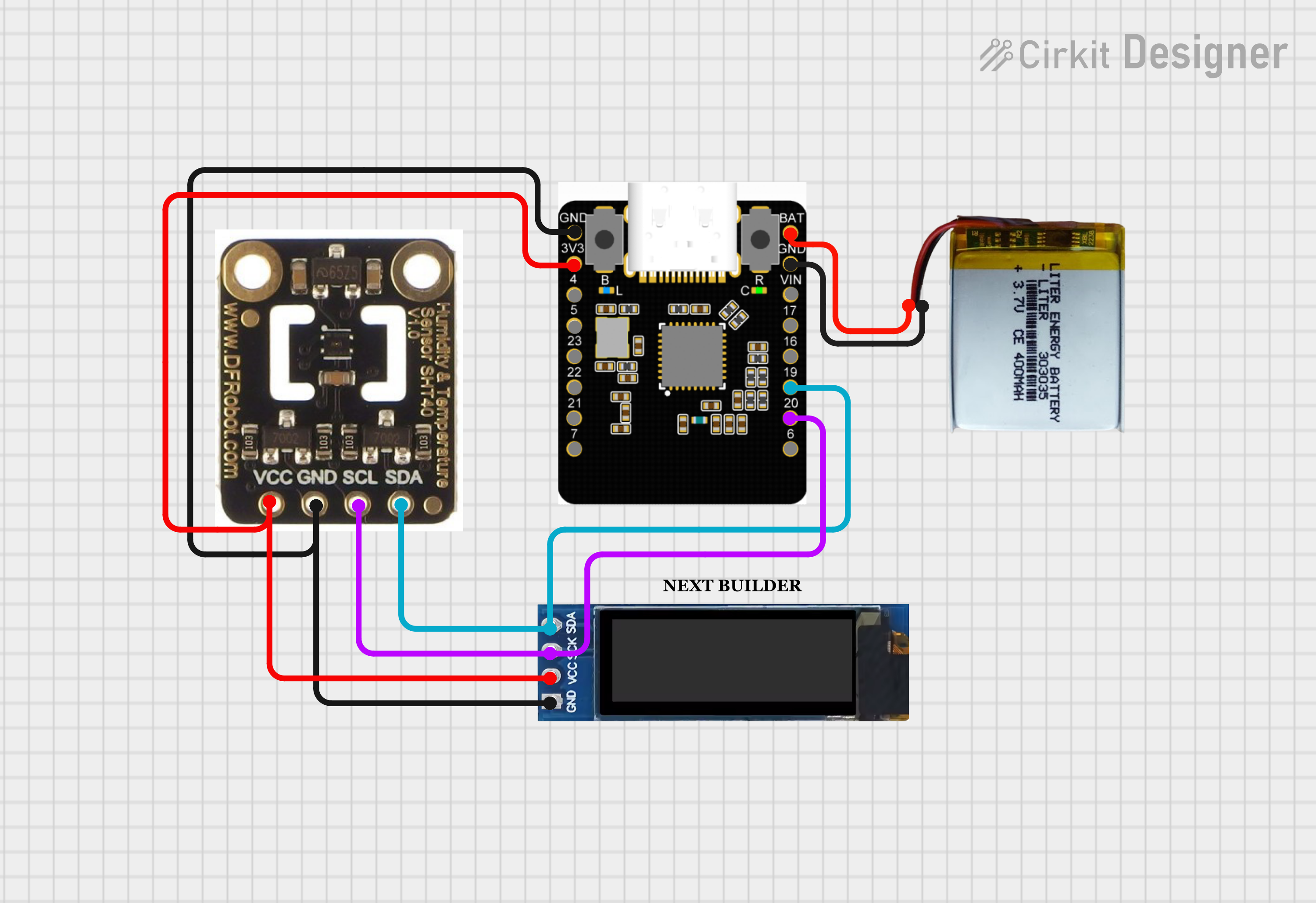
6Connection
![]()
It’s time to wire up all the components! Use the provided circuit diagram to make each connection carefully and double-check before powering the circuit.
Here are the pin connections:
OLED Display
- OLED Display SCL → Microcontroller SCL
- OLED Display SDA → Microcontroller SDA
- OLED Display VCC → 3V3 of Microcontroller
- OLED Display GND → GND of Microcontroller
Sensor
- SHTC3 Sensor SCL → Microcontroller SCL
- SHTC3 Sensor SDA → Microcontroller SDA
- SHTC3 Sensor VCC → 3V3 of Microcontroller
- SHTC3 Sensor GND → GND of Microcontroller
Battery
- Li-Po Battery → BAT and GND pin of Beetle ESP32-C3
I’m quite comfortable with soldering, so I soldered the wires after assembling all the components in place to make it neat and compact. However, if you’re a beginner, I highly recommend making all the connections before assembly — it will make wiring much easier and reduce the risk of damaging components
-
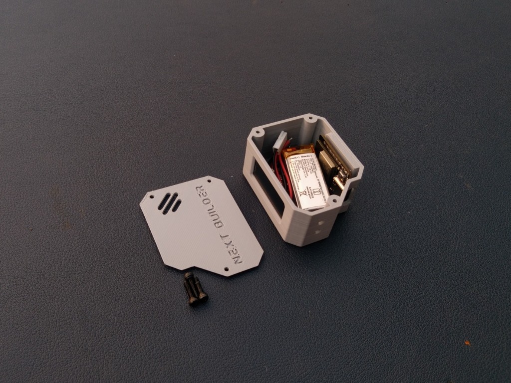
7Cover Assembly
![]()
![]()
![]()
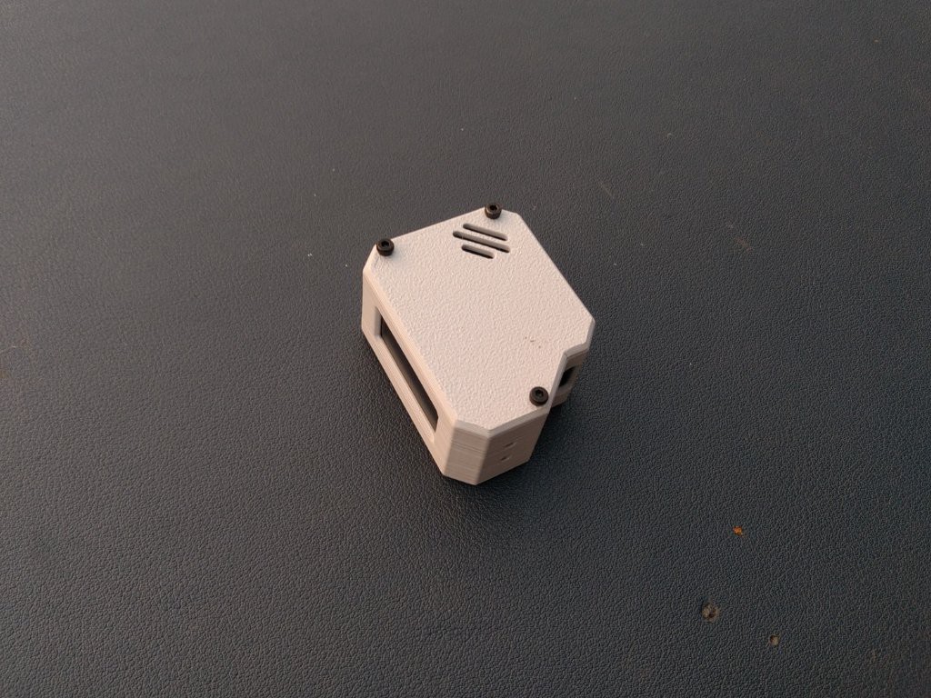
Once all the connections are done and checked properly, it’s time to close the case. Take the 3D-printed cover and carefully align it with the main body of the Orbit Clock. Make sure all sides fit perfectly.
Now, use three small M3 screws to secure the cover in place — this will hold everything tightly and give your mini satellite-style clock a clean, finished look
-
8Legs Assembly
![]()
![]()
![]()
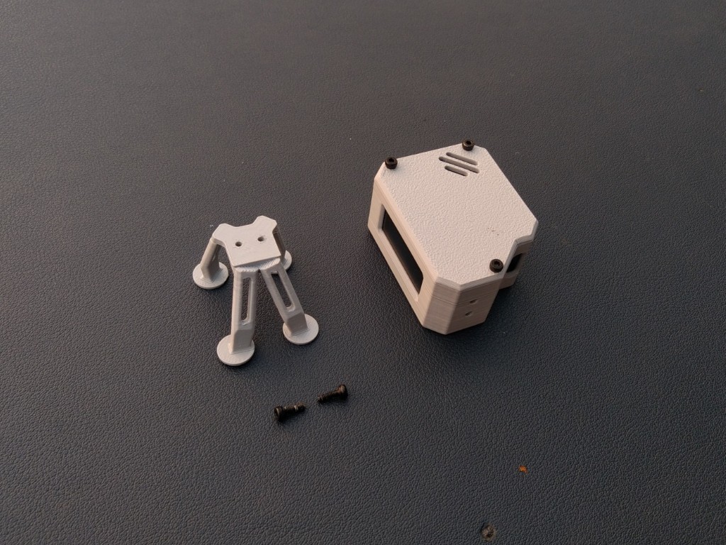
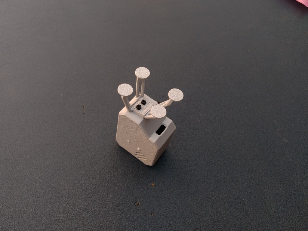
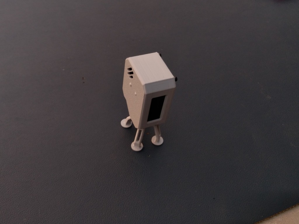
Once the cover is assembled, it’s time to attach the landing-style legs that give the Orbit Clock its unique satellite look. Take the 3D-printed legs and align them perfectly with their dedicated slots at the bottom of the body.
Use two small M3 screws to fix them securely in place. Make sure legs are tightened evenly so the clock stands straight and stable on any surface
-
9Code Setup
Before getting started, make sure you have the Arduino IDE installed on your computer and the ESP32 board package properly configured. If you haven’t done this yet, check out my previous project — it includes a complete step-by-step setup guide.
Credit: Inspired by the creative work of Mohit Bhoite. The code structure was referenced from Cumin Lander but completely rewritten for the Orbit Clock project.
Once ready, follow these steps to upload the Orbit Clock code:
- Visit the Orbit Clock GitHub Repositoryand download the complete project as a ZIP file.
- Extract the ZIP archive to your computer and open the.ino file in the Arduino IDE.
- Install the following required libraries from the Library Manager (Sketch → Include Library → Manage Libraries…):
- NTPClient.h
- Adafruit_GFX.h
- Adafruit_SSD1306.h
- Adafruit_SHTC3.h
Configure Wi-Fi
In the code, locate the section below:
// WiFi credentials
const char* ssid = "YOUR_WIFI_SSID";
const char* password = "YOUR_WIFI_PASSWORD";
Replace "YOUR_WIFI_SSID" with your actual Wi-Fi name and "YOUR_WIFI_PASSWORD" with your password.
Configure GMT Offset
The NTPClient library uses a GMT offset in seconds to adjust the time to your local time zone. For that Know your Country GMT offset then Convert GMT offset to seconds & put the value in Code. Example of India (GMT +5:30)
- 5 hours × 3600 = 18000
- 30 min × 60 = 1800
- Total = 19800 sec
In the code, locate this line and change the value according;)
// NTP setup
WiFiUDP ntpUDP;
NTPClient timeClient(ntpUDP, "pool.ntp.org", 19800, 60000); // IST: UTC+5:30
This ensures your clock shows the time according to your country Standard Time correctly.
-
10Uploading Code
Once your code is ready, connect your DFRobot Beetle ESP32-C3 to your computer using a USB cable. In Arduino IDE, make sure to select the correct board and port: go to Tools → Board → ESP32 Boards → DFRobot Beetle ESP32-C3 and Tools → Port → select the COM port your board is connected to. Click Upload in Arduino IDE. The IDE will compile the code and then upload it to your board.
OrbitClock – a Tiny Space IoT Environmental Clock
OrbitClock blends futuristic design with IoT tech. It shows real-time NTP time and environmental data in a sleek satellite-style form.


Discussions
Become a Hackaday.io Member
Create an account to leave a comment. Already have an account? Log In.
I'm 12 years old and my interests are 3D printing, space, and electronics. This is my dad's account, but we both use it to find fun projects. I'm going to try to make your project. Thanks for sharing.
Are you sure? yes | no