Gilhad
-
Composite output
11/13/2025 at 10:43 • 0 commentsThe composite output is currently done via USART running on half system clock.
One line is 64 uS long.
Sync pulse should be 0 V, black should be 0.3 V and white should be 1 V.
---------- more ----------![]()
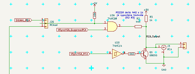
Logic signal goes to resistor divider over 440 Ohm to joint of 1k pullup to +5V and the 50 Ohm screen input. This was computed to make the requested 0.3 - 1 V levels.
Sync goes transistor (over NOT gate and 1k3 resistor) to pull that to 0 V. (and the resisors of divider limits the current from gates.)
As the USART lets its pin to flow, when disabled, the USART output goes via AND gate and Suppress signal keep the output LOW when no data are transmited.
In future (in this version) I want try to feed it from 74HC166 in similar way as VGA does it, to have 2x faster data here (same as system clock)
The jumper 40-80 selects the source, either USART (marked as 40 chars per line) or the 74HC166 output (marked 80 chars)
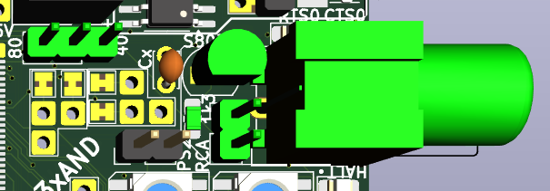
Here is the part on PCB
![]()
(top)
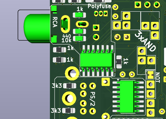
![]()
(bottom)
The RCA uses 1/4 AND gates of 74HC008 (the rest is avaiable as 3xAND blocks for future use) and 1/6 NOT gates of 74HC14 (4/6 are used by PS/2 and HALT, 1/6 is avaiable here too)
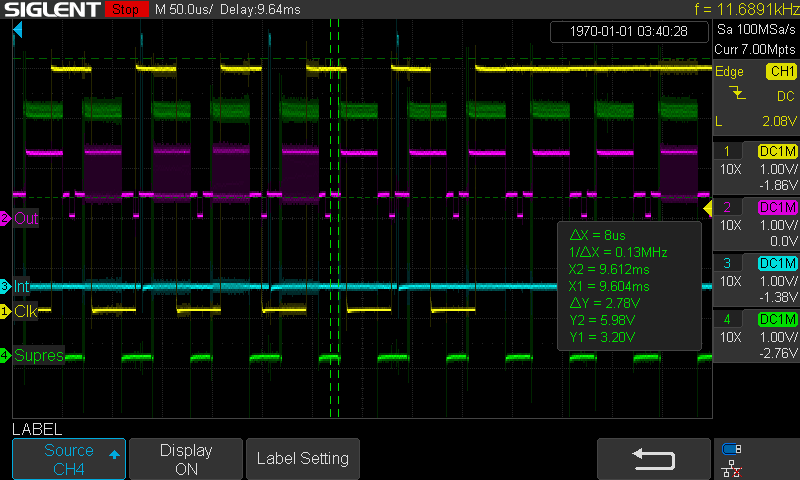
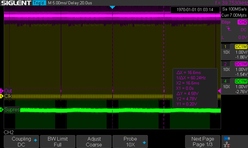
Here is osciloscope showing the RCA signal (magenta Out), Supress (green) and clock from PS/2 (yellow). The cyan Int is some debug.
![]()
Here we see the PS/2 traffic - pulses of similar width as RCA lines, but no synchronisation possible. Magenta Out show 0V sync pulses and 0.3V-1V data accompanied dark area before and after visible line.
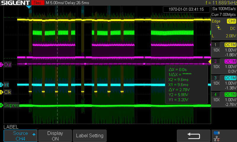
Here is osciloscope of 3 full screens and 8 PS/2 codes - around vertical sync is blank area bellow and above visible screen and the sync is way longer there.
![]()
There is no time to produce both RCA and VGA signals at the same time, but it is possible to switch the output on the fly. But the monitors are slow and take few seconds to adjust and start showing incomming signal, so no smart tricks probabelly possible here.
-
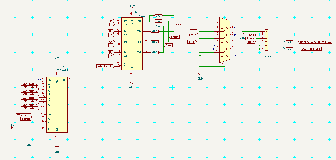
VGA
11/07/2025 at 12:32 • 0 commentsVGA need Vertical Sync (at start of each screen), Horizontal Sync (at start of each line) and Signal (inside the line, it is the pixels).
Vertical Sync is generated by timer on pin PE4 (every 16.64 mS ~ 60 Hz)
Horizontal Sync is generated by timer on pin PB6 (every 32 uS)
VGA signal is generated in interrupt on timer overflow (every 32 uS = each 512 clock ticks)
It needs pin PE7, where 16MHz (system clock) can be configured. As Arduino Mega does not have this pin connected, this was the main reason for making this PCB.
---------- more ----------Here are some osciloscope snaps, the magenta line is VSync, yellow line is HSync and green is Signal (sorry for wrong naming in picture)
![]() (4 screens at 60Hz)
(4 screens at 60Hz)![]() (1 line with pixels, 32uS)
(1 line with pixels, 32uS)
The main idea came from Squeezing Water from Stone 3: Arduino Nano + 1(!) Logic IC = Computer with VGA and PS/2 from slu4coder - short macro in assembler take character from videoram, take its definition from Flash, puts it as byte to port (PF here) and let 74HC166 to clock it out as 8 pixels. The macro take 8 clock ticks and is repeated 40x to output full line.
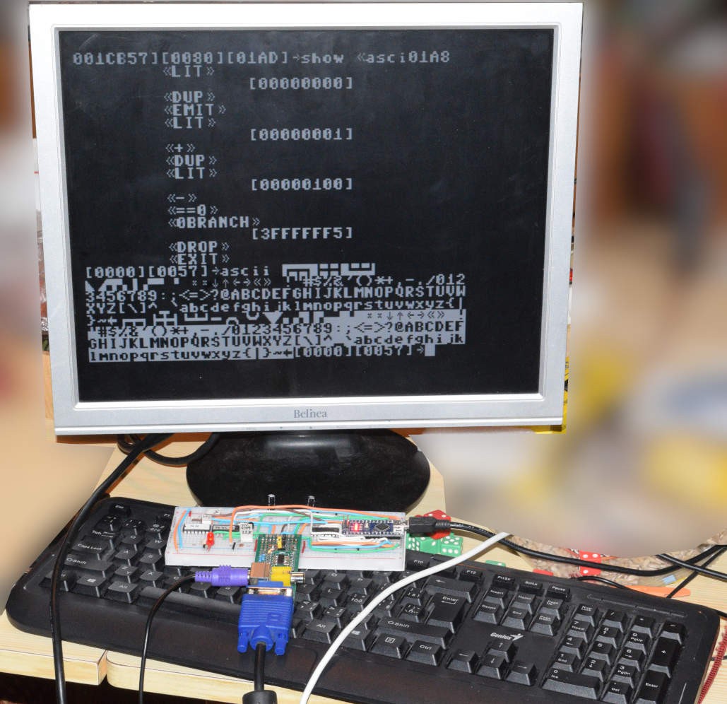
Each line is shown 2x so the visible area is 320x400 pixels, but is managed as 320x200 points (25 text lines) for readability and data size (character set takes 256 chars x 8 lines per character = 2kB of Flash.)
The numbers are: 32uS x 16MHz = 512 ticks. 40 characters x 8 ticks = 320 ticks, 512 - 320 = 192 ticks for everything else. When interrupt happens and interrupts are allowed (SEI) the MCU will finish instruction first, then serve the interrupt. This waiting for instruction end may take 1-3 ticks itself, so the interrupt may happen not really regularry and is necesery to adjust for that (macro check in my code). Also it needs to save registers, compute all adresses and offsets and manage possible PS/2 during the line. That may take approx 150 ticks together, leaving like 42 ticks between lines for user code to run in (means 8% speed only).
Then there are the black borders above and below the displayed image (only lines 60 .. 460 are visible), where the user program is mainly executed (which give like 20% of MCU power). It is not much, but a lot of work can be done anyway.
I set not only the Vertical Sync, but also the Horizontal sync to timers, so it does not depend on code exuting, which solved problem where VGA monitor sometimes went blank for few seconds (because some other interrupt or CLI..SEI section moved HSync pulse out of place and monitor get "confused and blank"). Now long uniterruptable section just make small glitch on screen, where pixels are horizontally moved for a frame (1/60 sec).
I also added 74HC157 IC to select foreground/background colors according to 74HC166 output, so now it is possible set foreground/background color for each line separately (I set it for all 16 lines of character the same now). The colors are set on port PH now at the start of visible line.
I also added VGA_ENABLE signal to cut off all pixels output in blank areas, so the ports (PF and PH) can be used for something else (I use PF for PS/2 input, leaving PH for user programs).
I also plan to make hooks on end of each visual line for "mini interrupts" and on end of last visible line (for "run at frame pause" synchronisation of larger blocks, like SD card) to run in interrupt context.
On user level the change of variable frames can be used for synchronisation of larger blocks or for timing events.
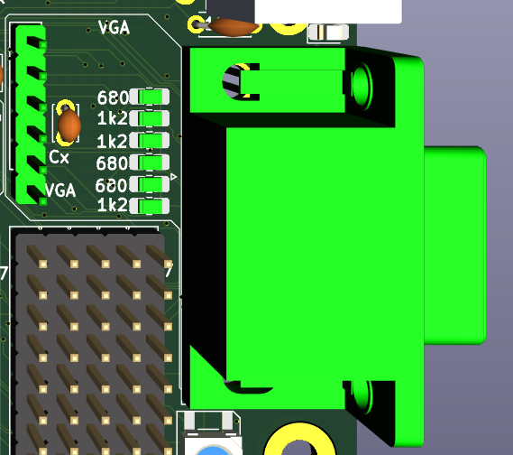
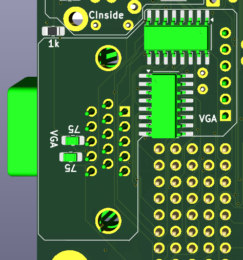
Here is schema and placement of the chips on PCB:![]()
![]()
![]()
Also note, that PB7 (VGA_Latch) is SYSTEM_LED on Arduino, so I placed LED between RCA and PS/2 connector near HALT LED and conected it here. When using VGA the LED will shine with approx 1/8 intensity. -
How it started
11/05/2025 at 12:46 • 0 commentsMany years ago I bought Omen Kilo (SBC with HD6309) and start to play with it. It worked, but did not anything visible (does it even run?), just communicated over Serial. Which was not so much satisfying.
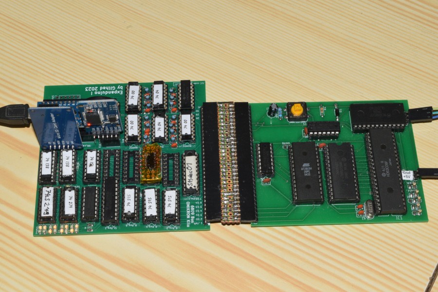
---------- more ----------So I invented and constructed card for 8 serial channels and called it Expanduino (pages in Czech only and incomplete), as it was Arduino based.
![]()
It worked somehow, but was mechanically unreliable, slow and did not allowed for more extensions.
So I decided to make my own design from the start and make it simply extensible, so it culd have everything a computer needs - output to some monitor, input from keyboard, filesystem to store and load data and programs, ports and so on and so on. This was not SBC anymore.
I also found Composite video from Arduino UNO from ceptimus and Squeezing Water from Stone 3: Arduino Nano + 1(!) Logic IC = Computer with VGA and PS/2 from slu4coder which looked like solution for the video output. I use their ideas (and many others) and reworked it to system, which can switch between VGA and RCA even on runtime. This looked as good foundantion for videocard I wanted.
First public presentation was on 2024 Maker Faire in Prague, in form of Computer at price for dinner as proof of concept.
I then expanded it to FORTH driven breadboard computer NanoHomeFORTH and started work on even better version with more RAM and power.
![]()
I called the project MegaHomeFORTH, as it was based on Arduino Mega, but then I discovered, that the most importaint pin (16MHz clock) is not accessible on Arduino Mega, nor on Arduino Mega Pro, so I went to make my own board, where it will be all included.
On that time the PCBway reached to me and told me, that the project prom Maker Faire catched their interest and that they will sponsor me with PCB for it, should I make the plans. I offered the new project instead, as it made more sense for me and they agreed. It took me 2 months to came with the first version MHF-001 and they manufactured the board for it.
![]()
The PCB was nice, simple to use, soldering there was easy for normal parts, but I had problems with the MCU and the RAM as the footprints I used was for machine soldering, but I had to solder this with my hands and eyes. MCU went well after lot of effort, but I could not solder the RAM reliably even after many attempts. It sometime worked, sometime not and sometime helped to press it with fingers. The pads for its pins was too small for me to make it reliable. The PCB itself managed well even when I repeatedly solder and desolder the pins, the problem was my handwork. Anyway it prove the concept, the RAM worked well sometimes.
Also other parts worked, it generated nice VGA signal with color lines, it generated RCA signal too, it read PS/2 keyboard and it even was able to read SD card while doing all the previous at the same time (I was using some Arduino library, where I hacked the millis() mechanism, as I used the interrupt for other purposes, I read one byte at time at each frame to do not collide with the VGA, so it got speed 50 char/sec, but it proved the concept).
I also published it as project there.
There was problems with USB connector, mainly because small footprint, it was torned from the PCB more time due my manipulation and was not as reliable as I wanted, but the desing did not allowed for other connection to MCU (except for ISP programming), so new concept for that was included to the new step too.
So I took another 2 moths to redesign it, added more features, made more logical configuration, and improved everything I could and now I am here, with MHF-002, which have more circuits on it, new module for USB, debug NeoPixel LEDS and so on and so on, which PCBway also offered to manufacture for free as sponsoring - and it is just manufactured as I write this lines :)
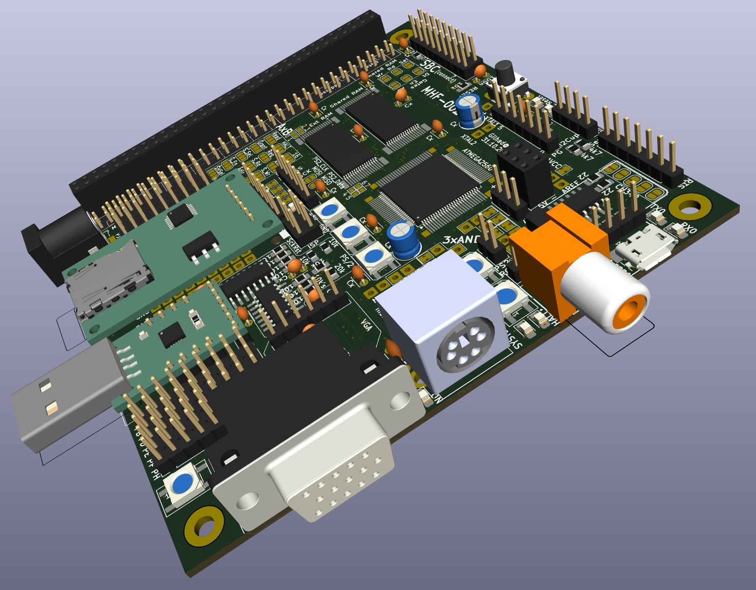
Here is 3D model, how it will look fully assembled:
![]()
I am looking for bring real photo soon :)
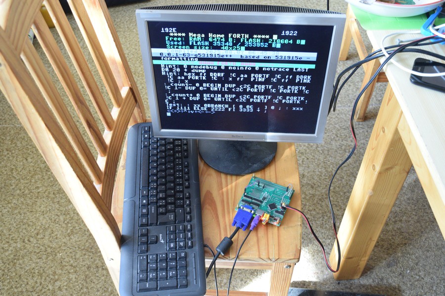
MHF-002 (Mega Home FORTH)
ATmega2560 based SBC with VGA, PS/2 and SD cards - meant to run FORTH now and serve as graphic card later.
 (4 screens at 60Hz)
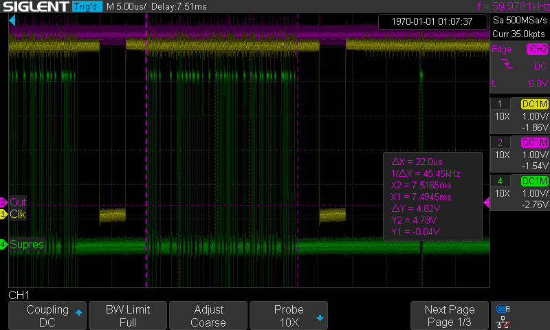 (1 line with pixels, 32uS)