 Arnov Sharma
-
1PCB Assembly
![]()
![]()
![]()
![]()
![]()
![]()
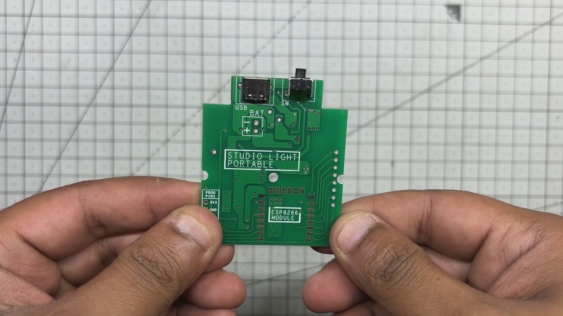
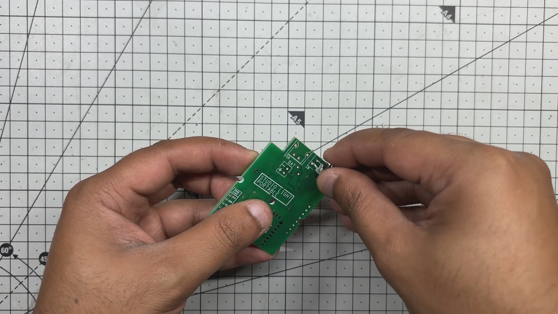
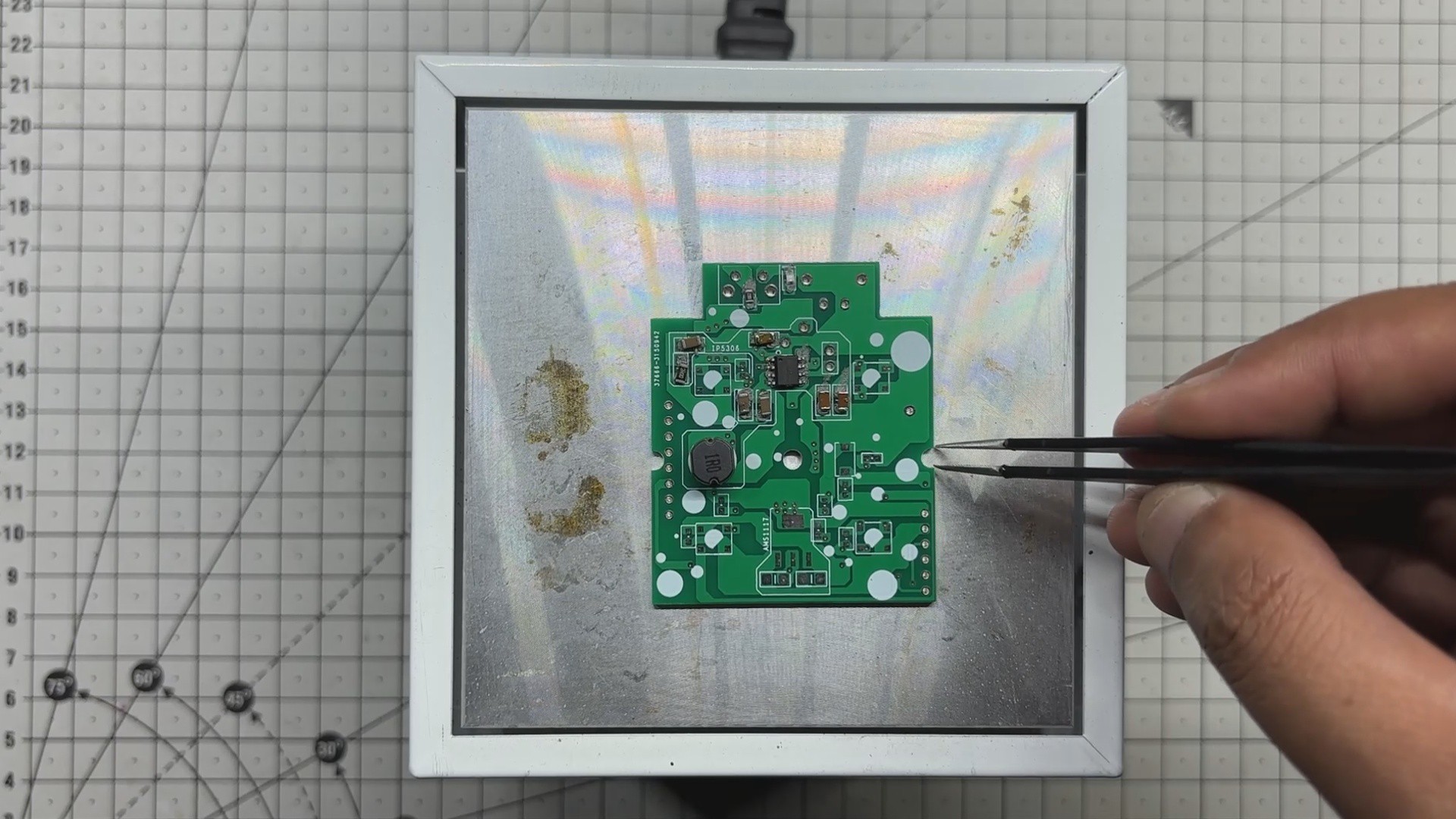
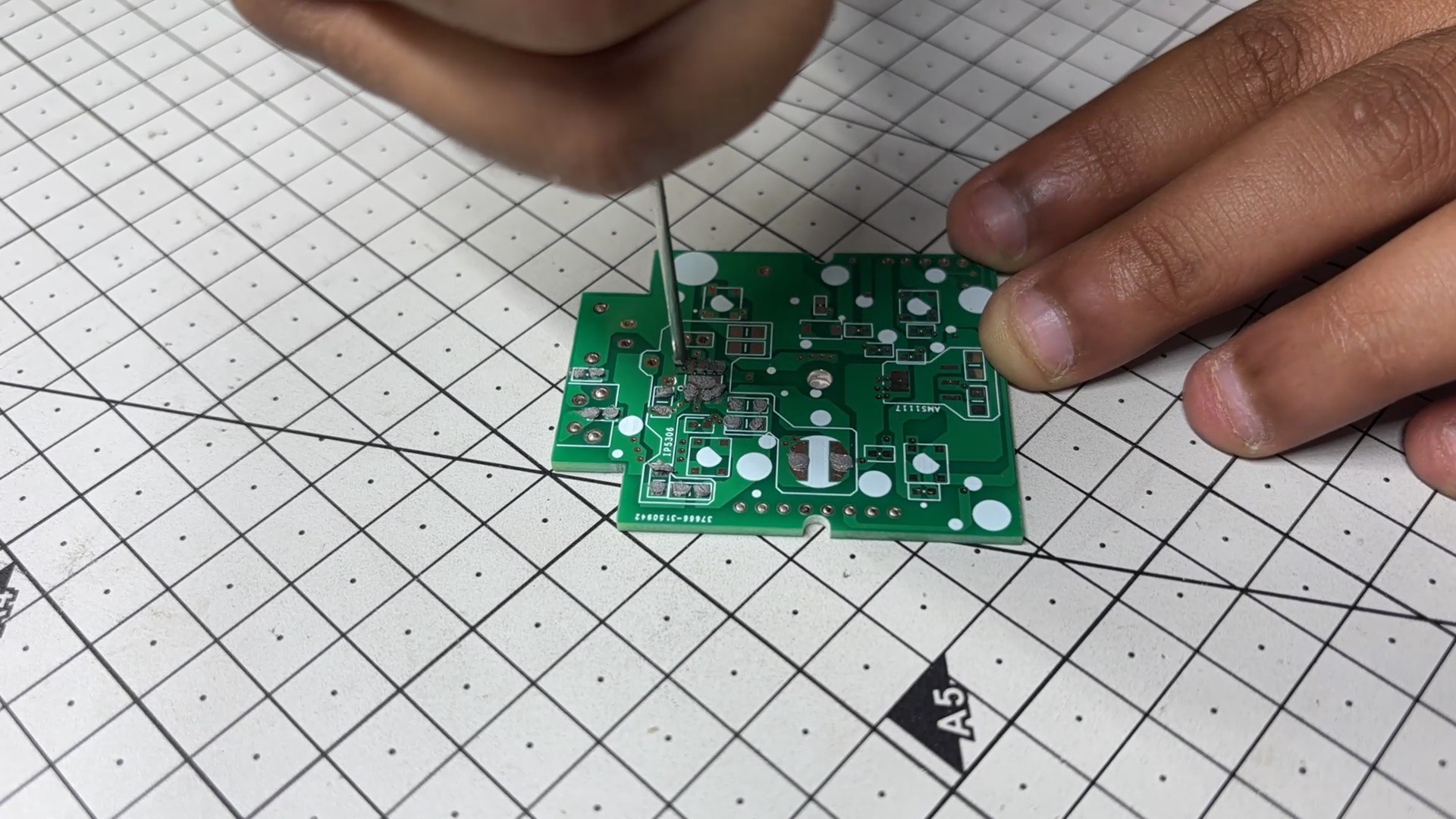
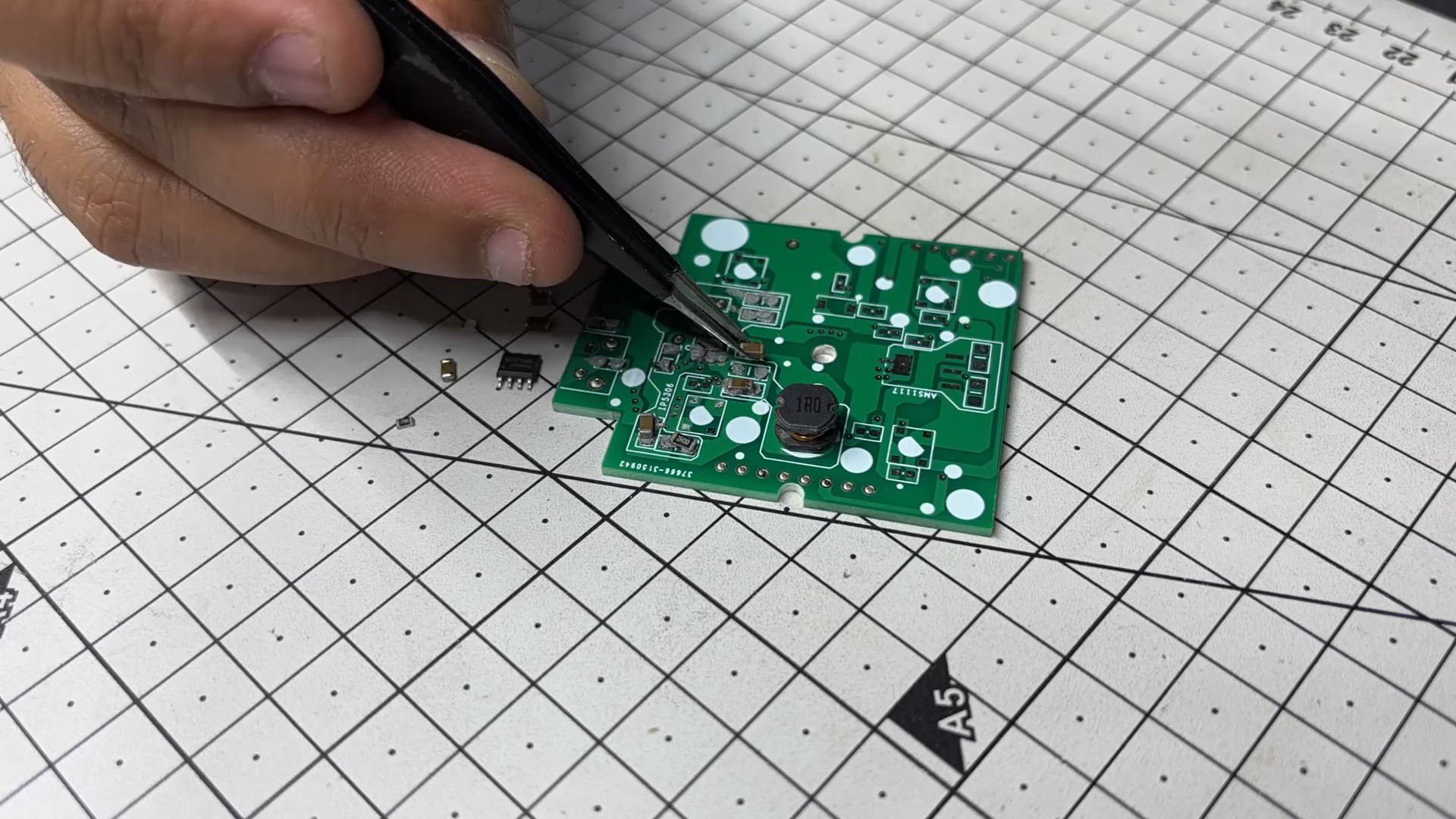
- The PCB assembly process begins by applying solder paste to each SMD component pad one at a time with a solder paste dispensing needle; we are using 63/37 Sn/Pb solder paste here.
- Next, we use an ESD tweezer to pick and arrange all SMD components on the top side of the board.
- We pick the circuit and place it on the Reflow hotplate, which heats the PCB to the solder paste melting temperature, causing all SMD components to permanently solder to their pads.
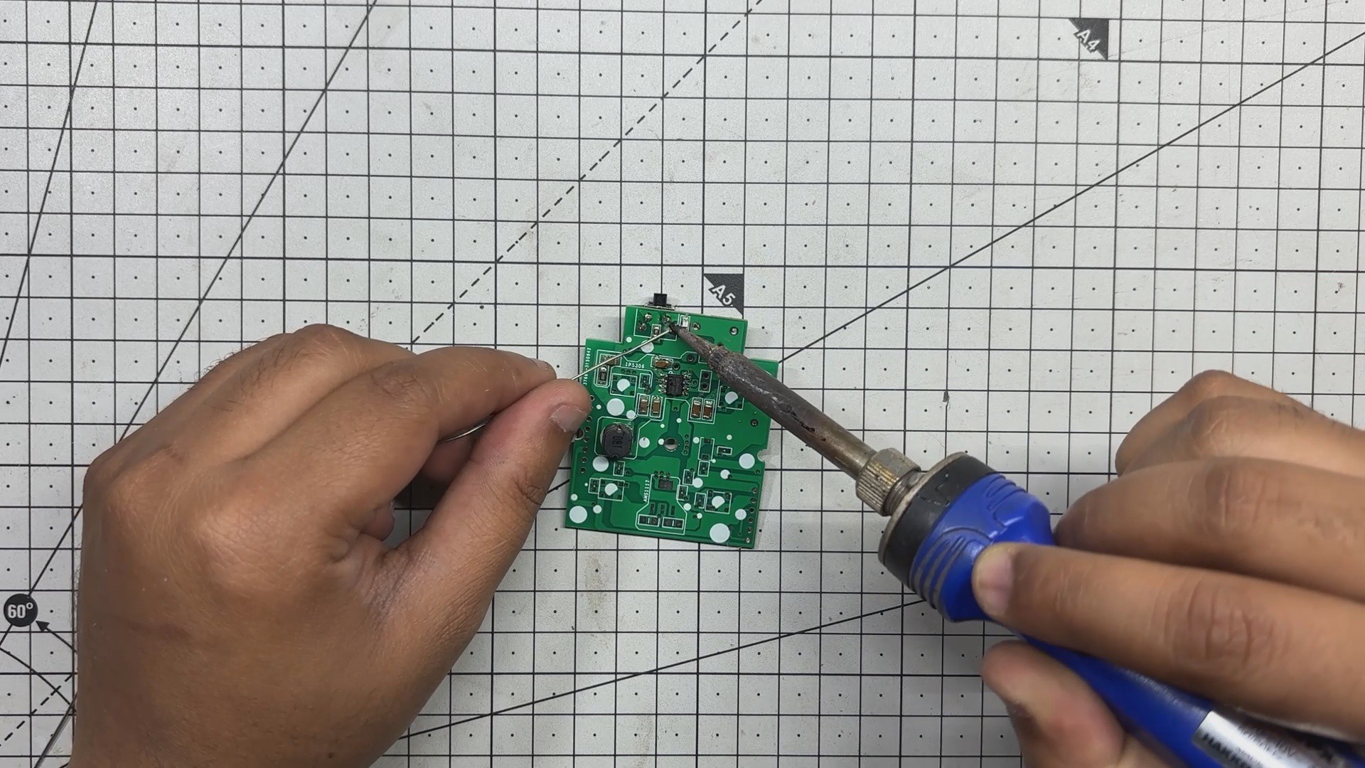
- Now come the through-hole components; we begin by installing the Push Switch, followed by the type C Port. Board is then filpped over and we solder both through-hole component pads using a soldering iron.
-
2Power Source
![]()
![]()
![]()
![]()
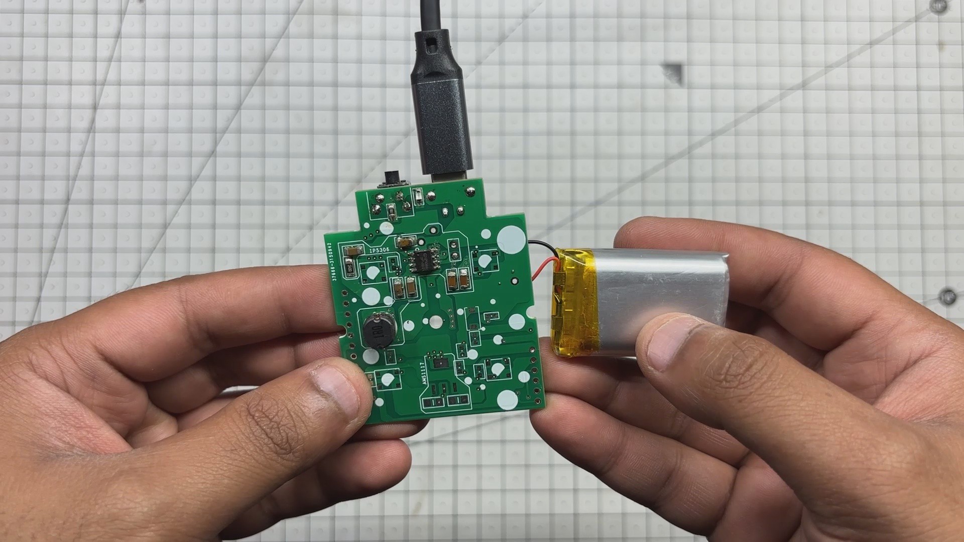
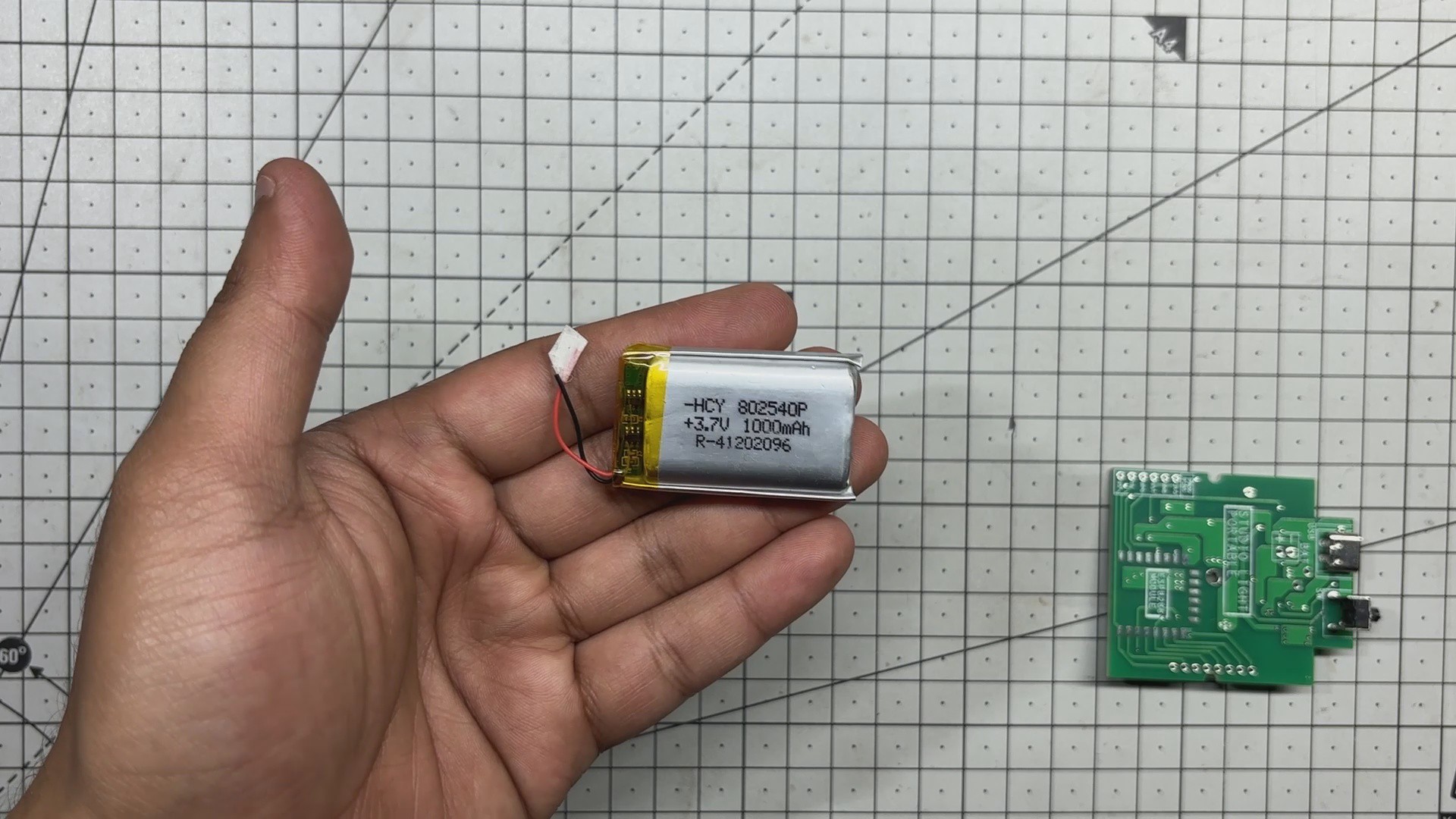
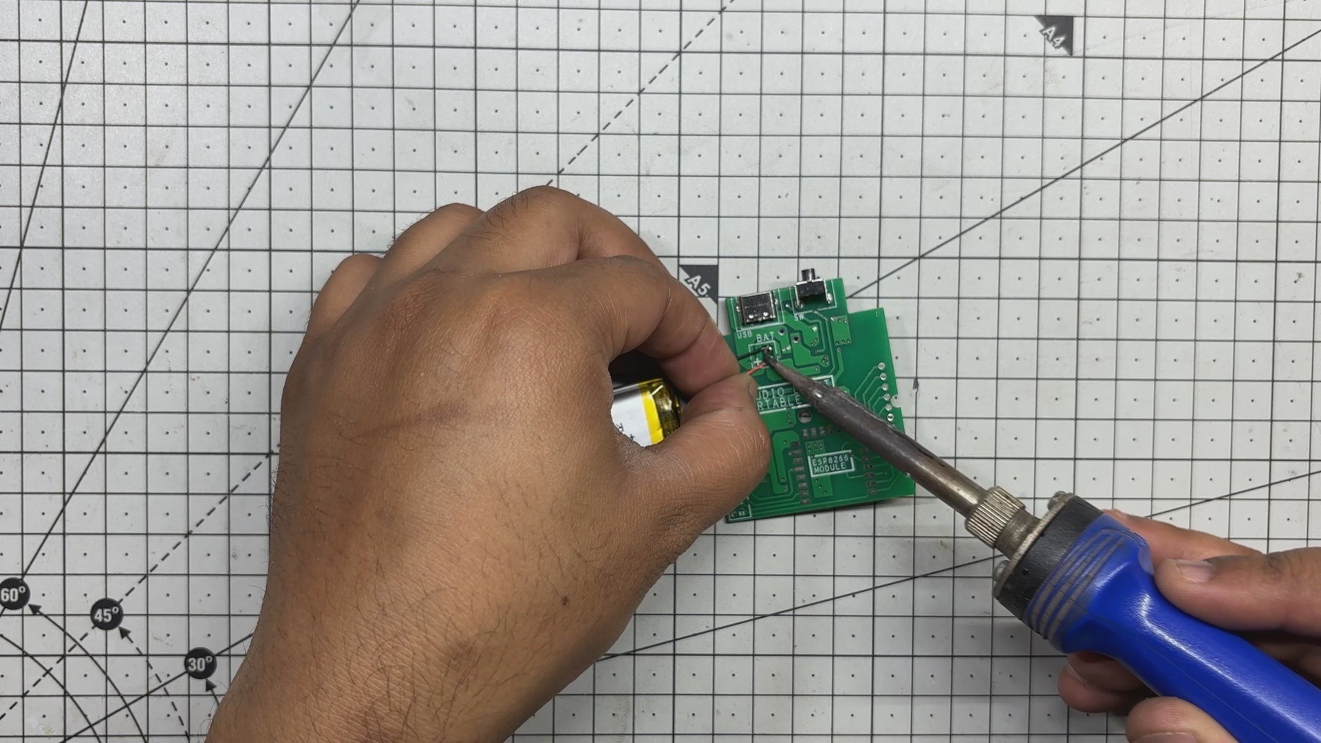
For power, we’re using a 3.7V 600mAh LiPo cell. Its positive and negative terminals are soldered directly to the battery connector on the power circuit. The system is activated by pressing a vertical push button, which powers up the board and lights up the indicator LED that confirms the setup is operational.
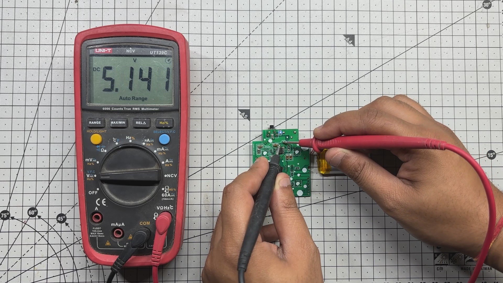
To verify, we measure the output voltage across the board, which reads a stable 5V.
Charging is straightforward: just connect a USB Type-C cable using any standard smartphone charger. During charging, the indicator LED blinks to show activity, and once the battery is fully charged, the LED remains solid to indicate completion.
-
3WIRING
![]()
![]()
![]()
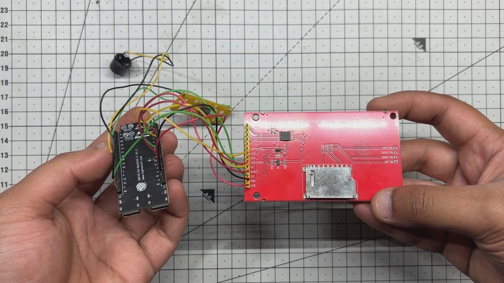
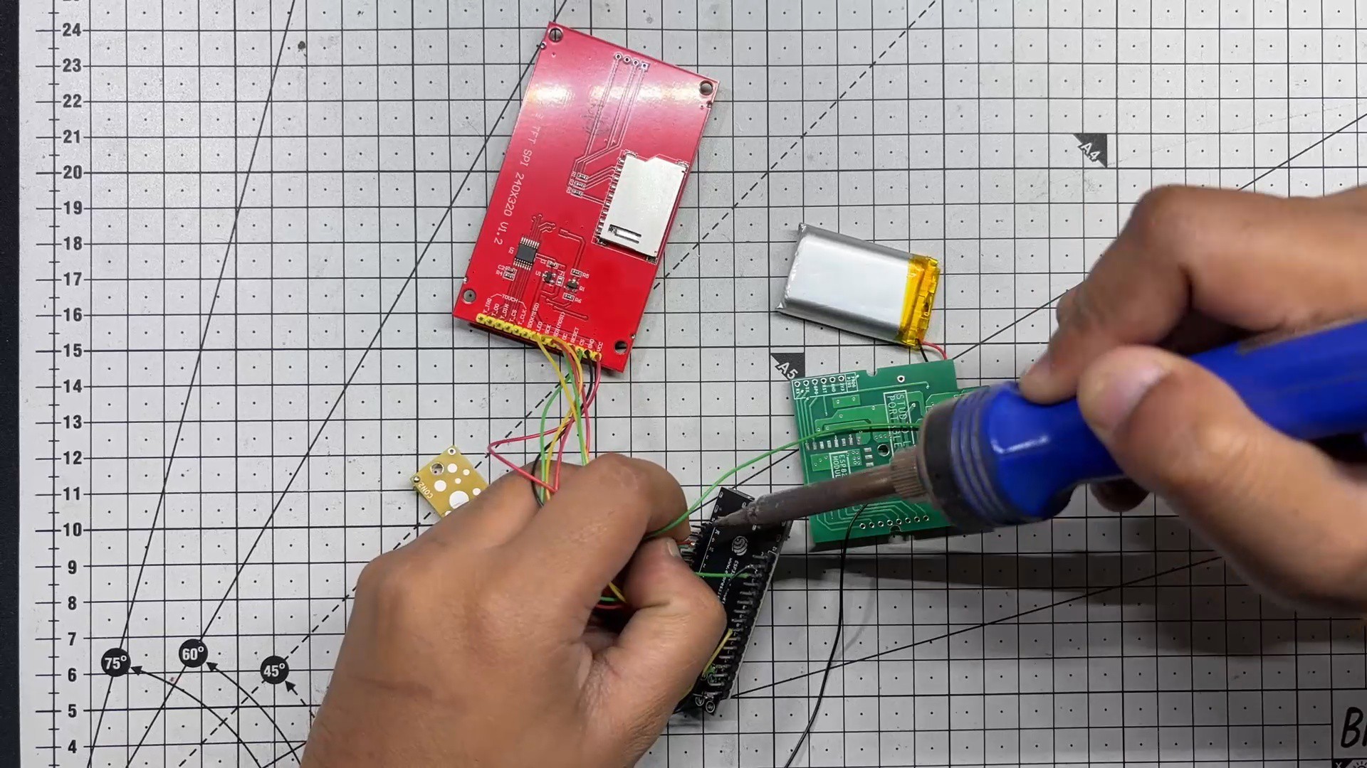
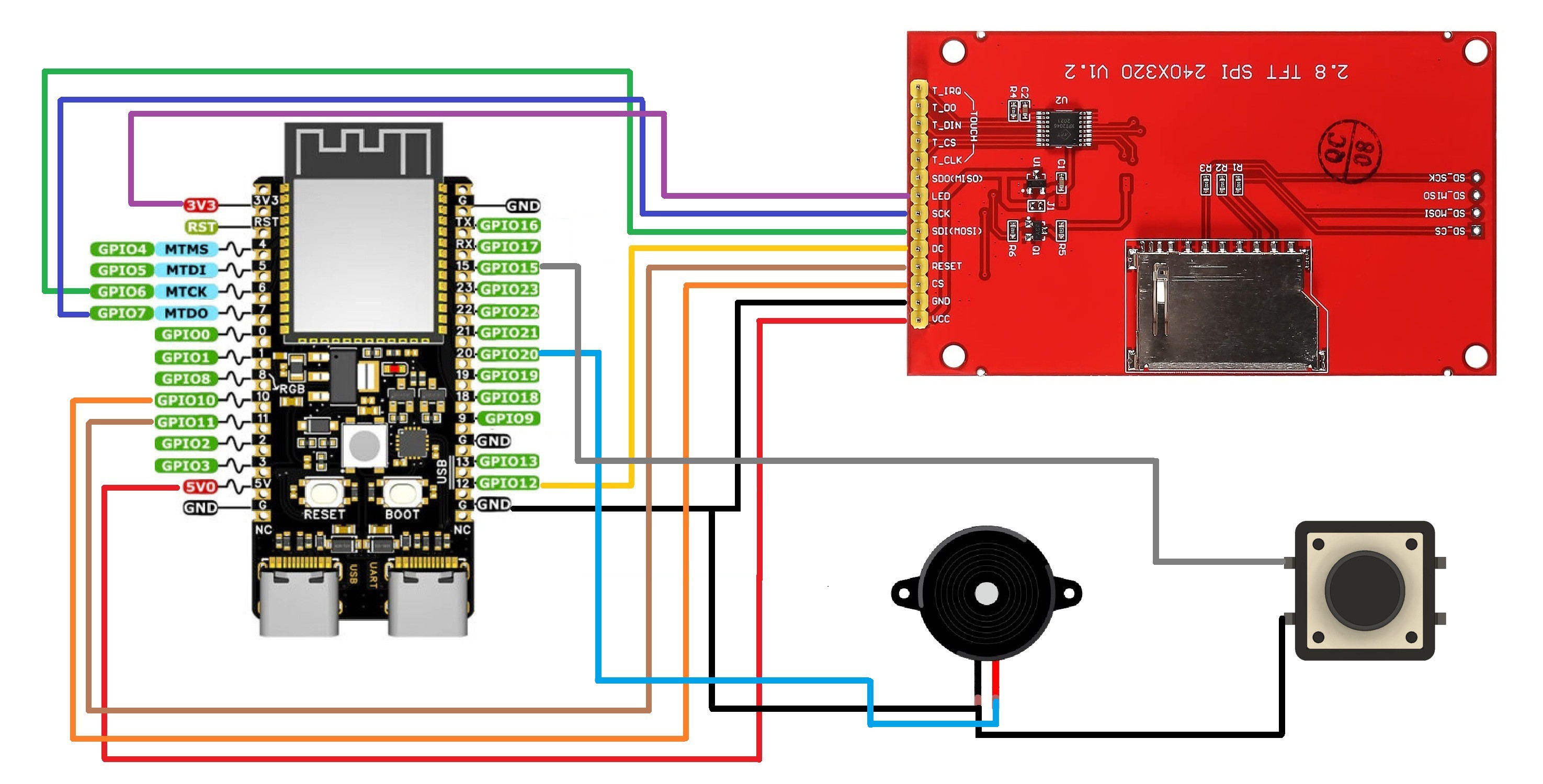
We now start the wiring process, which begins by connecting the TFT Display with the ESP32 C6 Dev kit in the following order.
- DISPLAY's MOSI to GPIO6
- SCK to GPIO7
- Chip Select to GPIO10
- Reset to GPIO11
- DC to GPIO12
- The LED Pin of Display goes to 3.3V of the DevKit.
- VCC goes to 5V
- GND to GND
We’ve reused a button PCB from a previous project; it features a 6×6 push button mounted on a small board that fits neatly into our enclosure. The button’s signal pin is connected to GPIO15 on the ESP32-C6, while the other terminal is tied to ground.
Additionally, we’ve integrated a buzzer with the ESP32-C6 dev kit. The buzzer’s positive lead is wired to GPIO20, and its negative lead is connected to ground.
To complete the power setup, we’ve connected the output of our IP5306-based power circuit directly to the ESP32-C6 dev kit: 5V goes to the dev kit’s 5V input, and ground is shared between both boards, finalizing the entire wiring process
-
4Front Enclosure—Screen Assembly
![]()
![]()
![]()
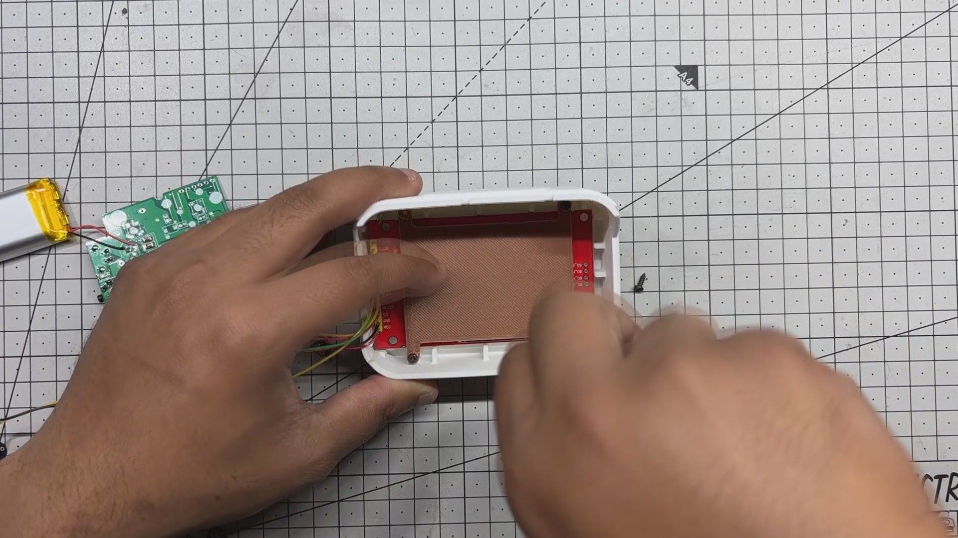
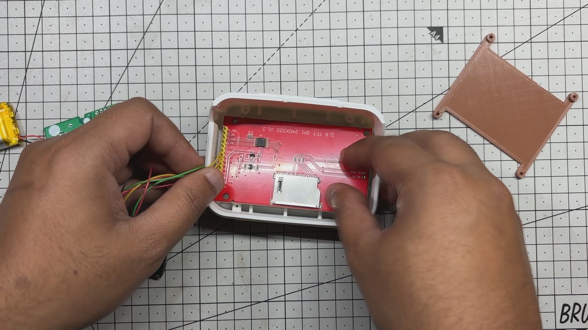
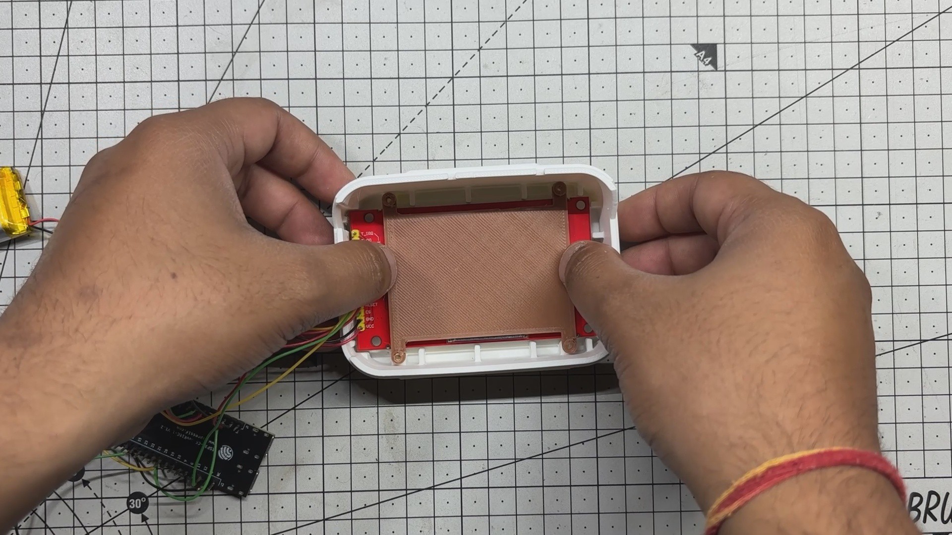
- The front enclosure assembly begins with positioning the ILI9341 display into its designated mounting slot.
- Once aligned, we secure it using a holding plate, which is fastened with four M2 screws. This plate ensures the display remains firmly in place and properly seated within the enclosure.
-
5Back Enclosure—Power Circuit and Switch Assembly
![]()
![]()
![]()
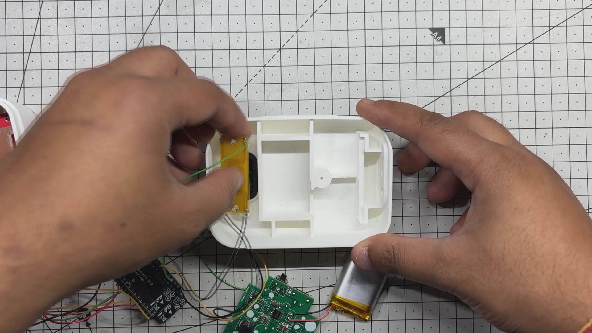
The back enclosure assembly begins with inserting the switch actuator into its designated slot. Once in place, the button PCB is positioned directly above it and secured using two M2 screws, ensuring the actuator can reliably press the onboard push button when triggered.
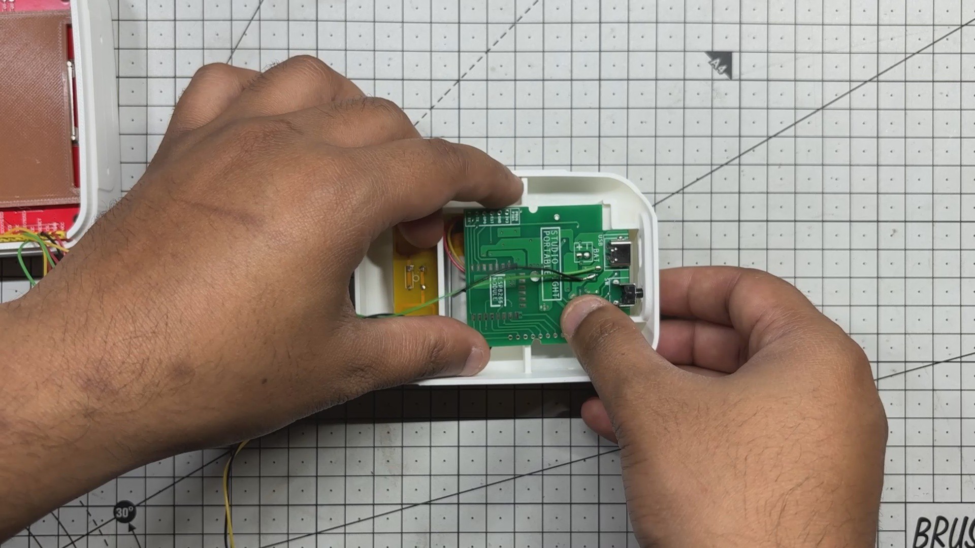
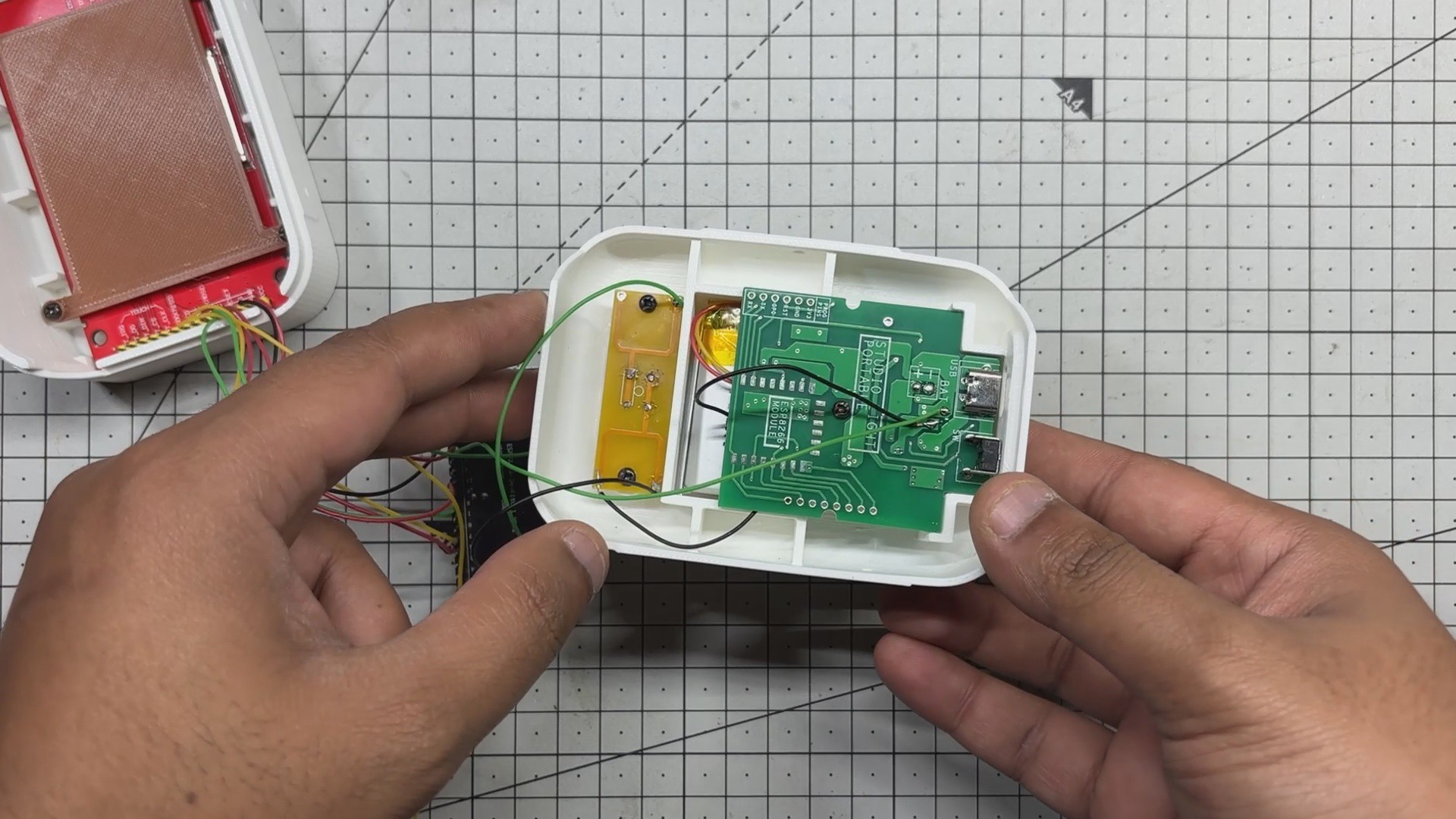
Next, the LiPo cell is carefully placed into its allocated compartment. The power circuit is then aligned over its central mounting boss and fastened with a single M2 screw. This not only secures the board but also holds the LiPo cell firmly in position beneath it, completing the internal layout of the rear section.
-
6Final Assembly
![]()
![]()
![]()
![]()
![]()
![]()
![]()
![]()
![]()
![]()
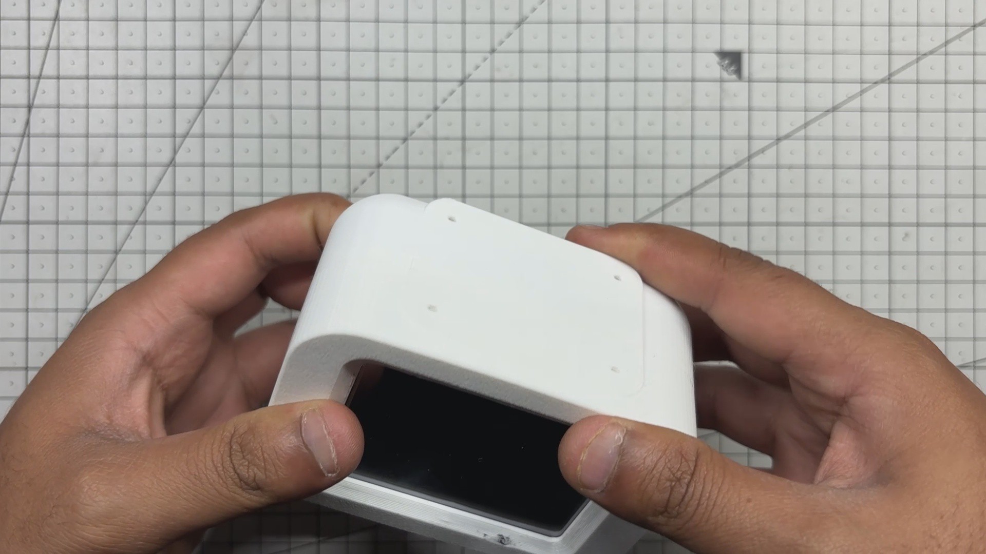
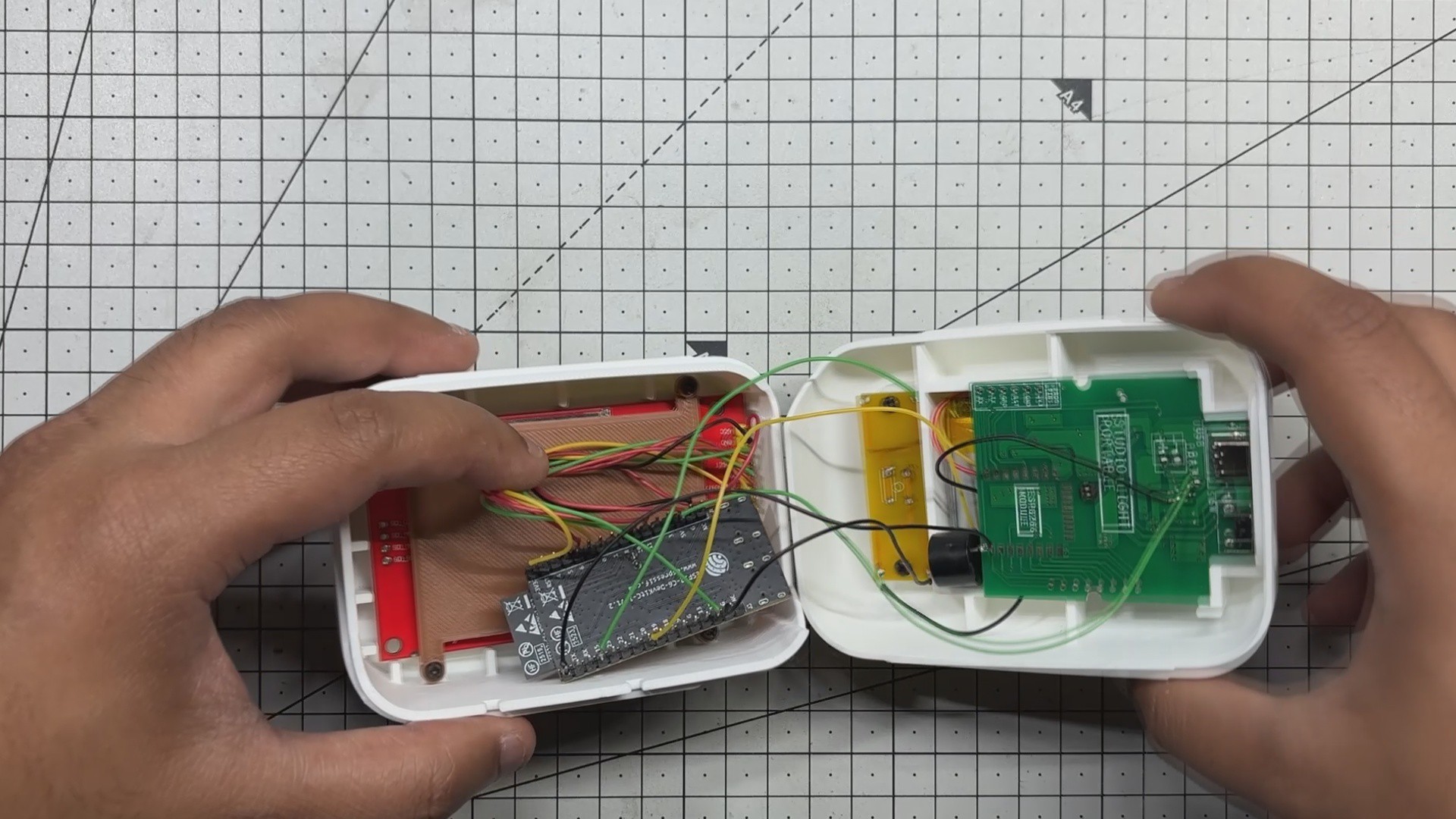
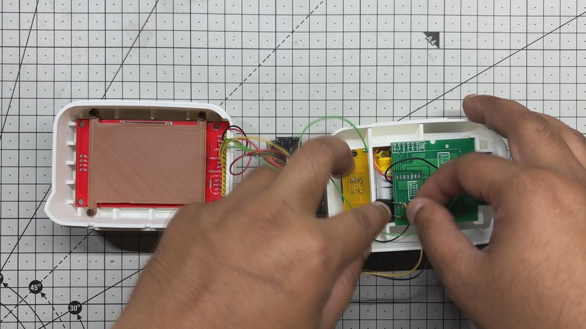
- Assembly starts by placing the buzzer in its designated spot. Next, the ESP32-C6 Devkit is mounted onto the screen holder, and the front and back sections of the enclosure are closed together.
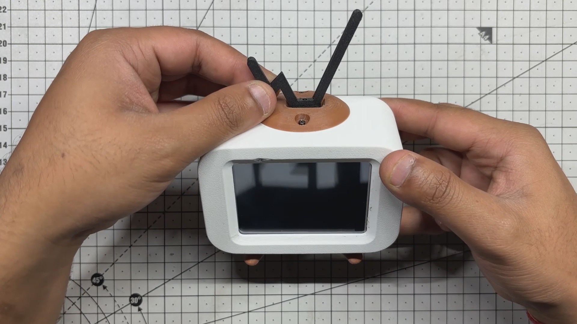
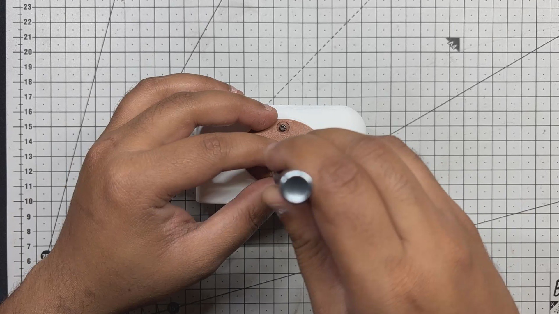
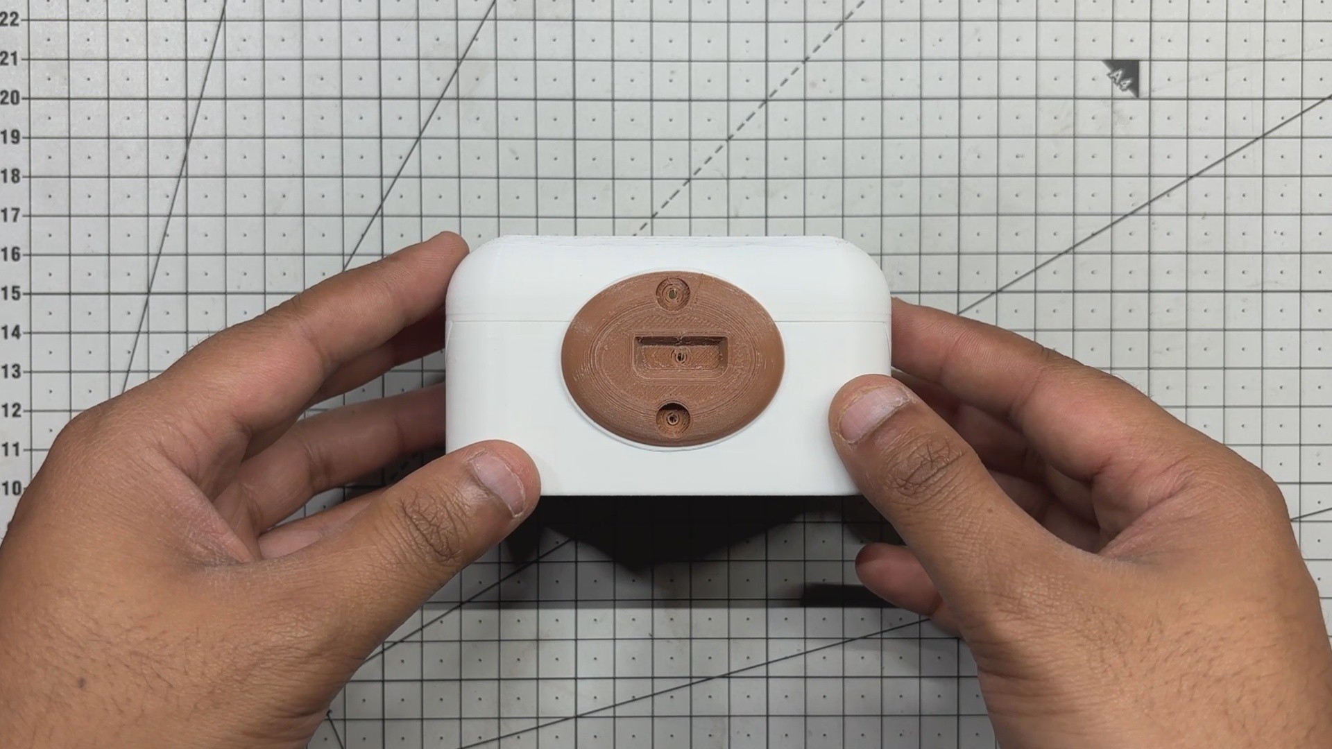
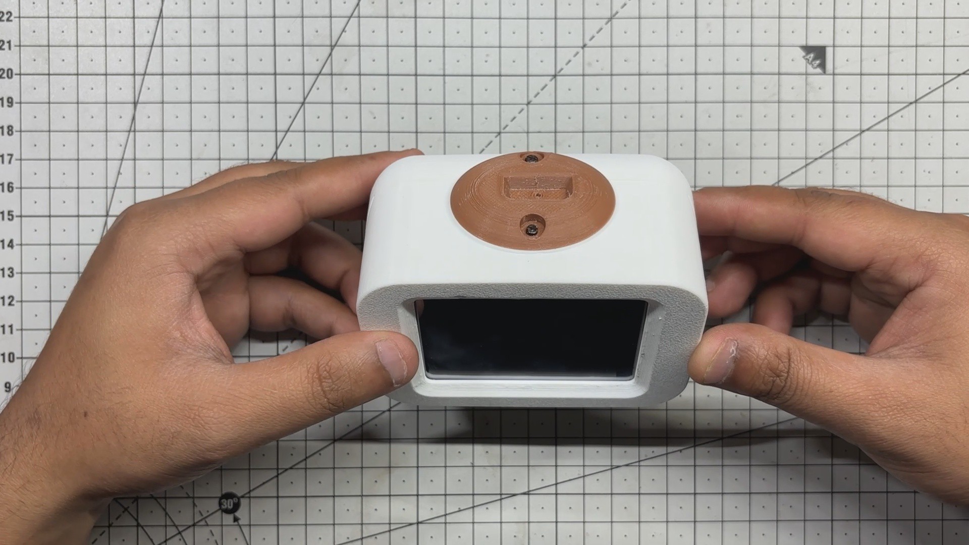
- The antenna holder is then positioned on top, aligned with the parting line, and secured using two M2 screws, locking all three sections firmly in place.
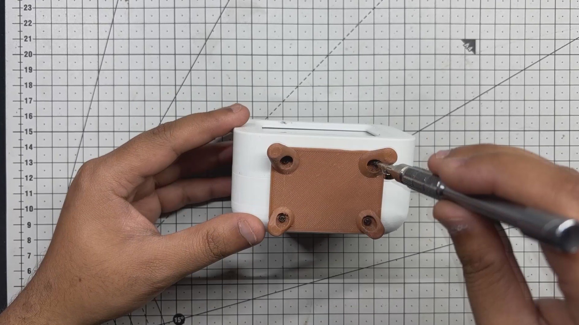
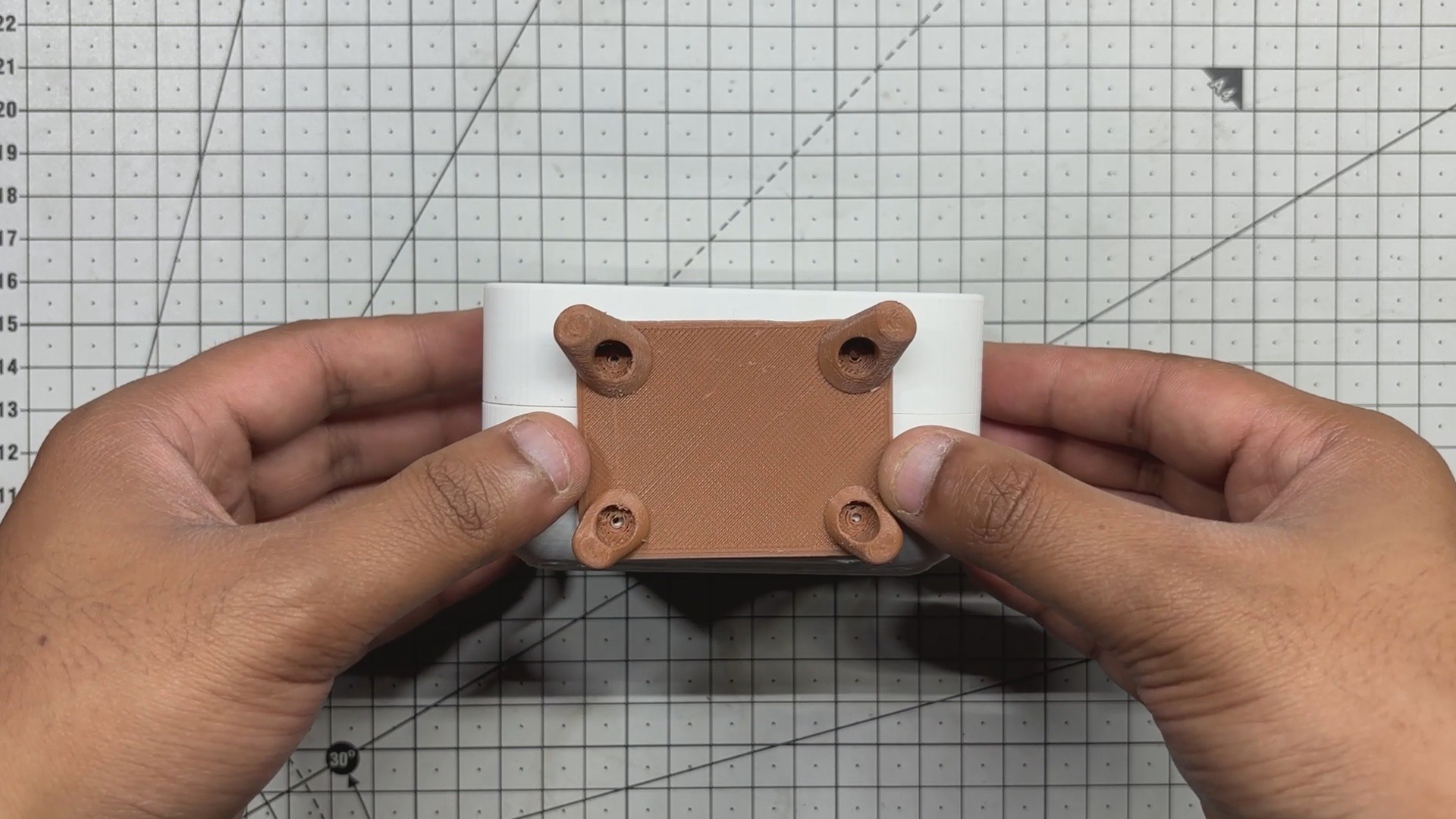
- From the bottom, the stand is attached and fastened with four M2 screws. Like the antenna holder, the stand also reinforces the connection between the front and back halves.
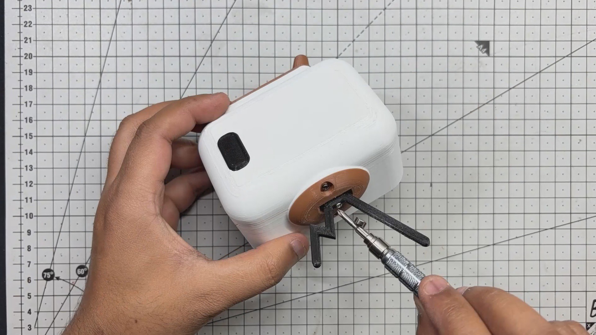
- Finally, the antenna is mounted onto the holder and secured with a single M2 screw. With that, the full assembly is complete.
-
7Result
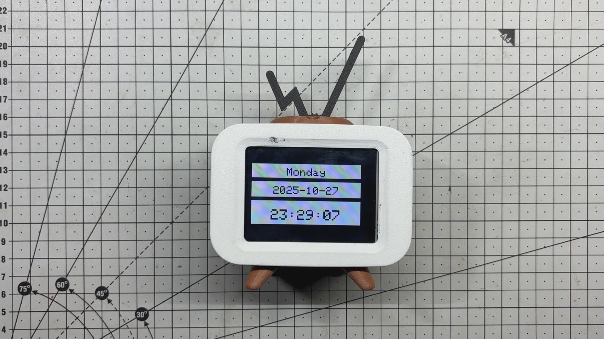
End Result of this build is a fully functional hybrid that doubles as a desk clock and a Snake game console. It fetches real-time data over WiFi and seamlessly switches into game mode, controlled via an Xbox controller paired over BLE. The ESP32-C6 handles everything smoothly, delivering reliable performance throughout.
Powered by a 3.7V 600mAh LiPo cell, the setup offers a solid 6–7 hours of backup, which is reasonable given the power demands of the ILI9341 display. For future iterations, switching to an E Ink display could drastically cut power consumption and extend battery life, which is a promising upgrade for long-term use.
-
8Clock and Gaming
![]()
![]()
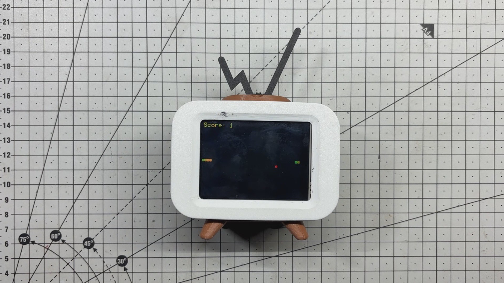
By pressing the Back switch, the desk clock seamlessly transforms into a Snake game console. Once the Xbox controller is powered on, it automatically pairs with the ESP32-C6 via Bluetooth Low Energy (BLE), allowing instant gameplay using the left joystick.
As the snake consumes each food dot, the score counter increases and the snake grows progressively longer. If the player accidentally collides with the snake’s own body, the game ends and the score resets, just like the classic rules.
When you're done playing, a simple press of the same switch reverts the setup back to its original clock mode, making the transition between timekeeping and gaming smooth and intuitive.
Special thanks to HQ NextPCB for providing components that I've used in this project; check them out for getting all sorts of PCB or PCBA-related services for less cost.
Thanks for reaching this far, and I will be back with a new project soon.
SerpenTime
Serpentime is a digital internet clock that transforms into a retro Snake game console at the press of a button
Discussions
Become a Hackaday.io Member
Create an account to leave a comment. Already have an account? Log In.