Arnov Sharma
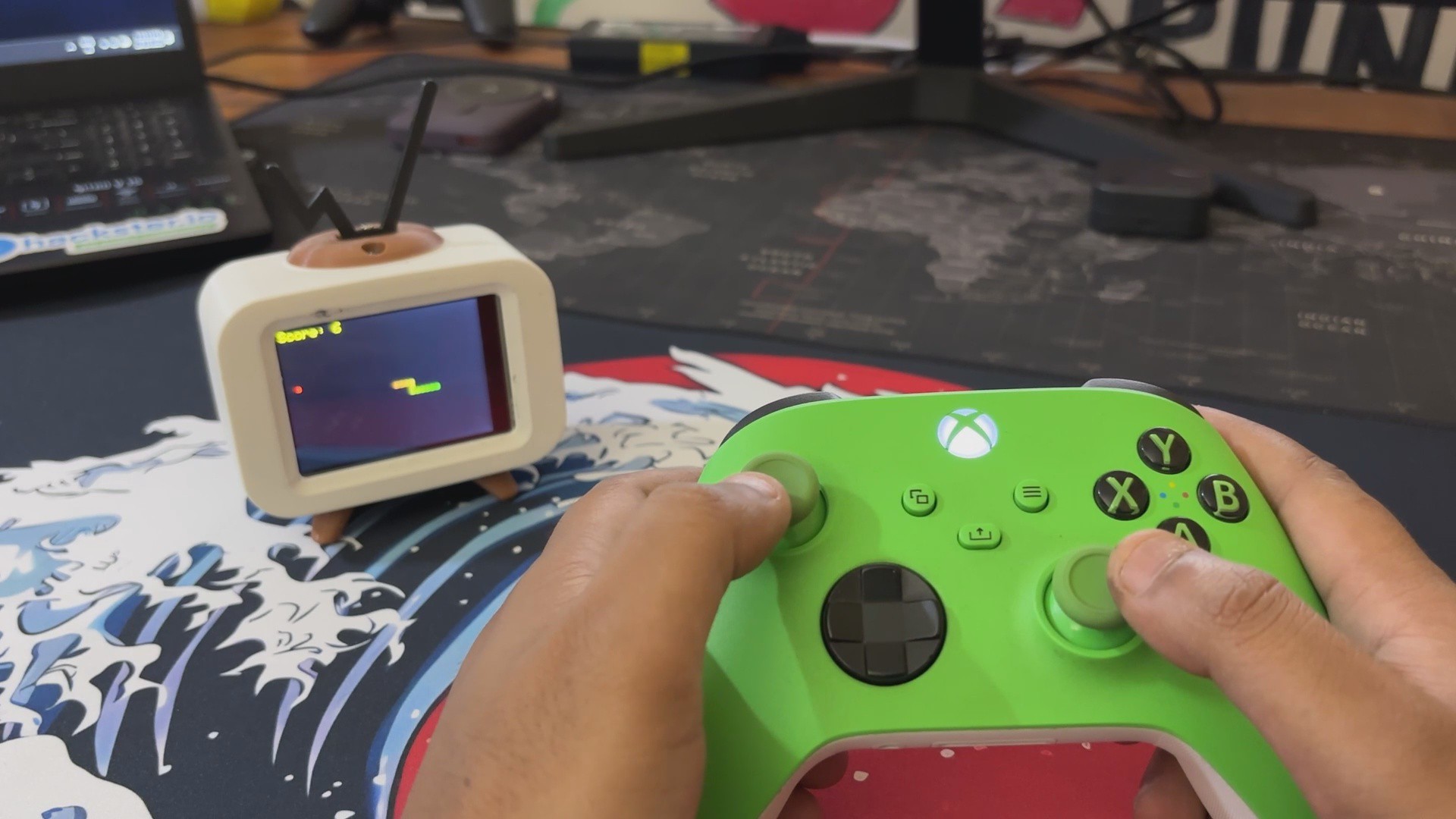
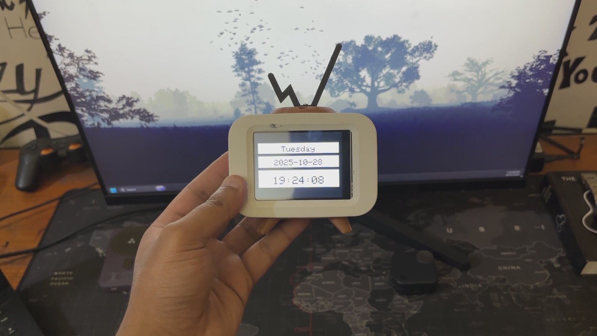
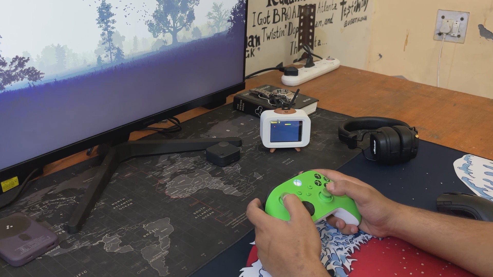

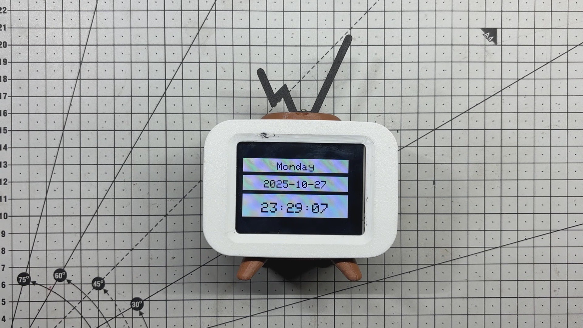
Serpentime is a compact, dual-mode creation that blends the utility of a digital clock with the charm of a retro Snake game console. With a single button press, it shifts from timekeeper to game machine, powered by an Xbox controller for a surprisingly immersive experience.
In clock mode, it fetches time, date, and weekday data via NTP and displays it in crisp white panels with bold black cut-out text.
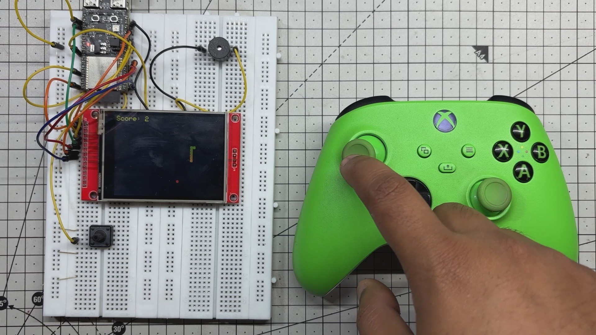
Switch to game mode, and you’re greeted by a smooth Snake game driven by the controller’s left joystick, complete with gradient snake segments, pulsing food, and a live score overlay.
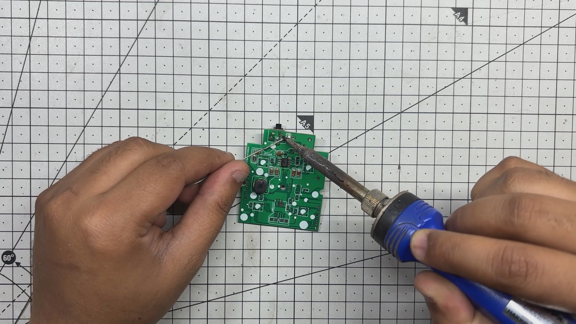
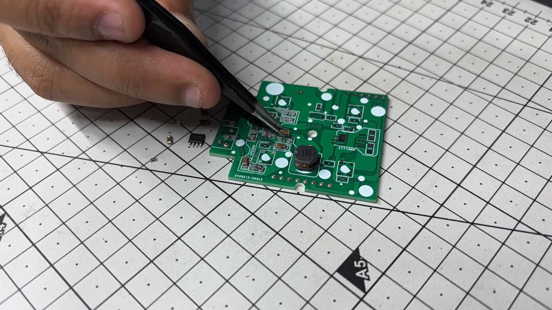
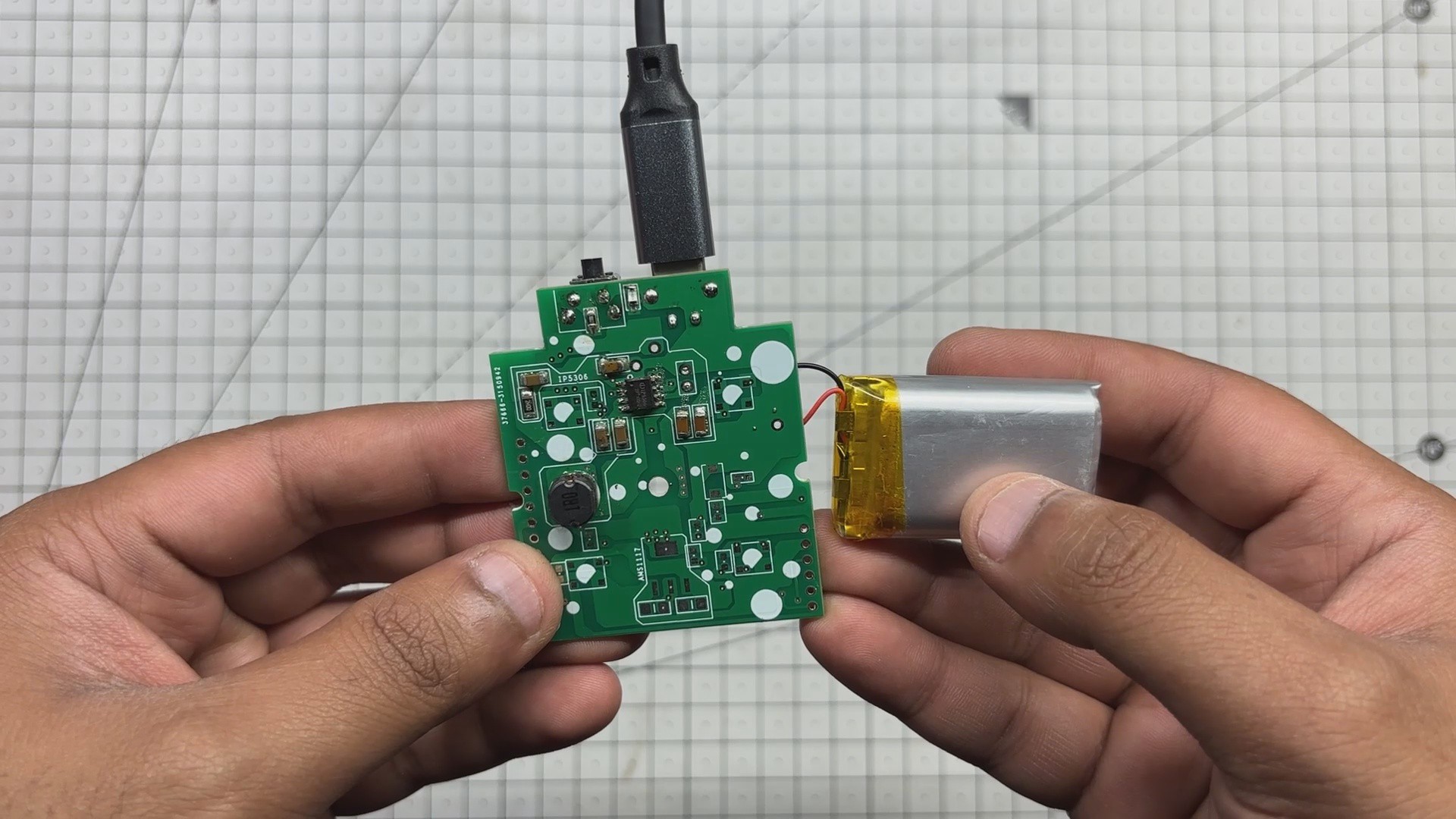
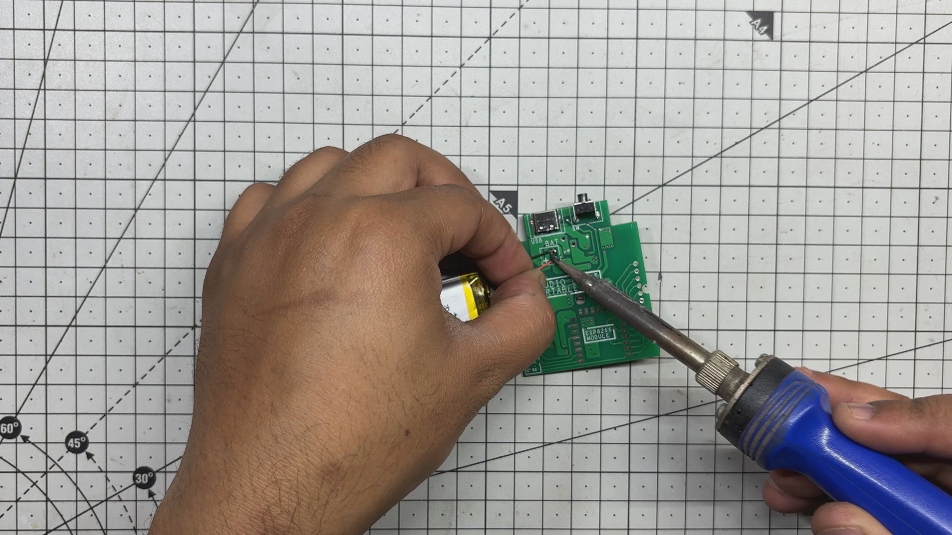
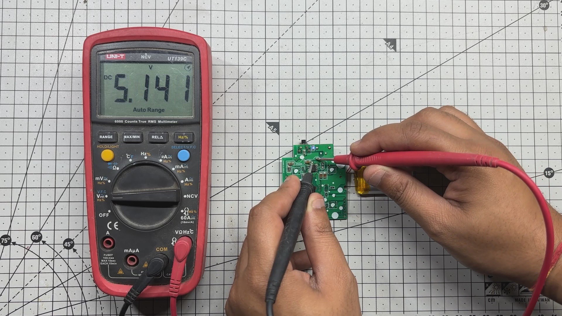
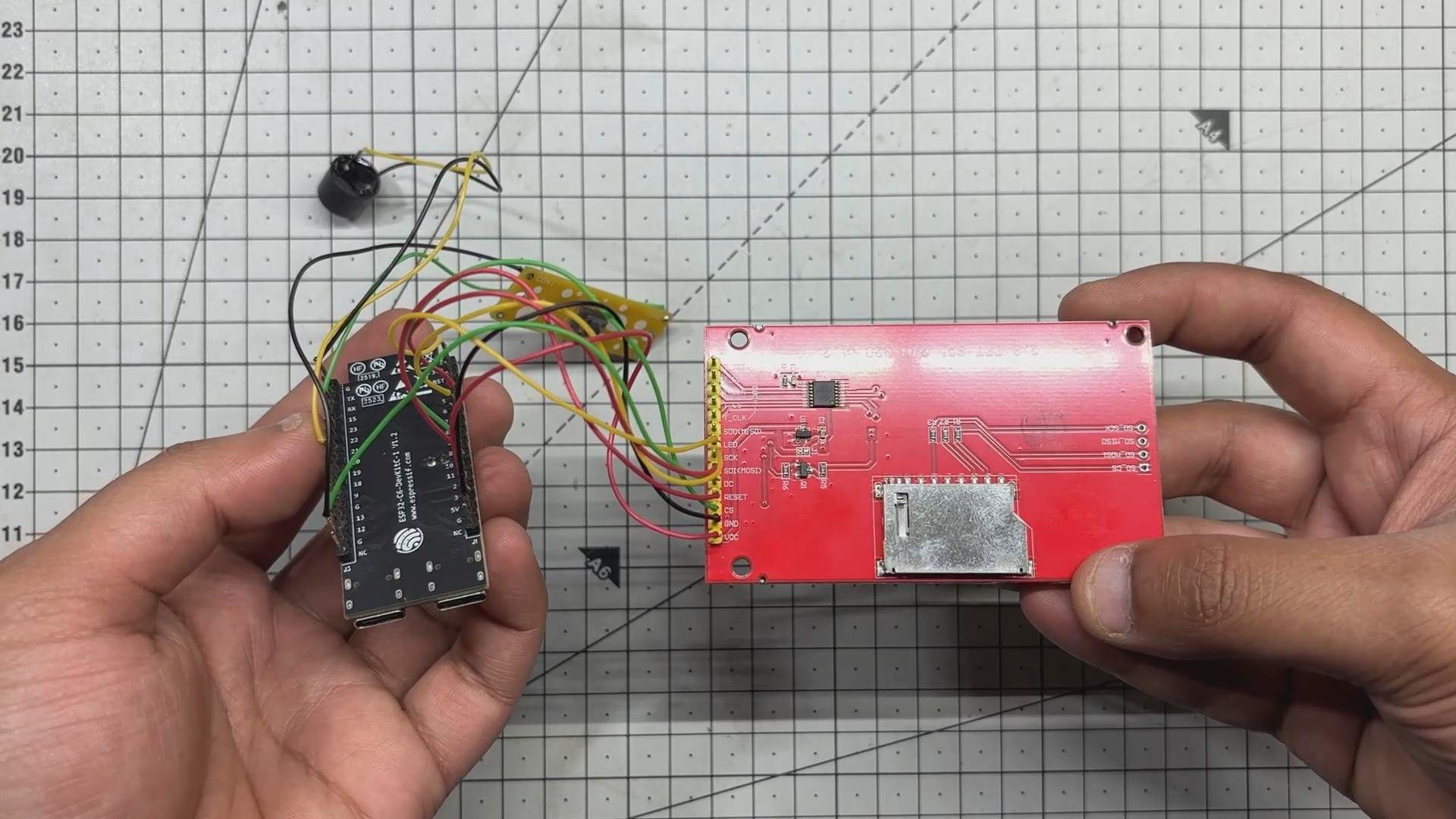
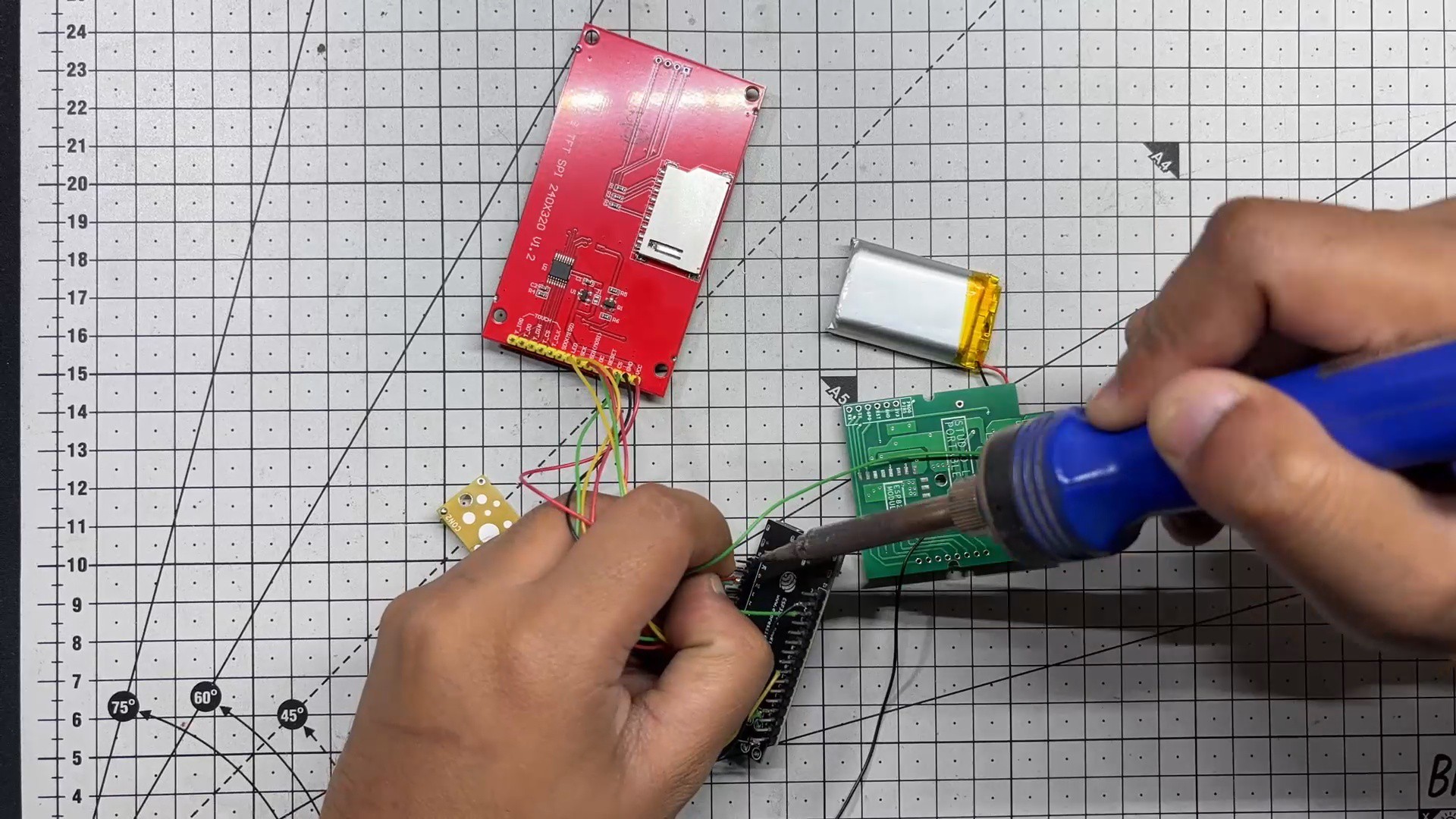
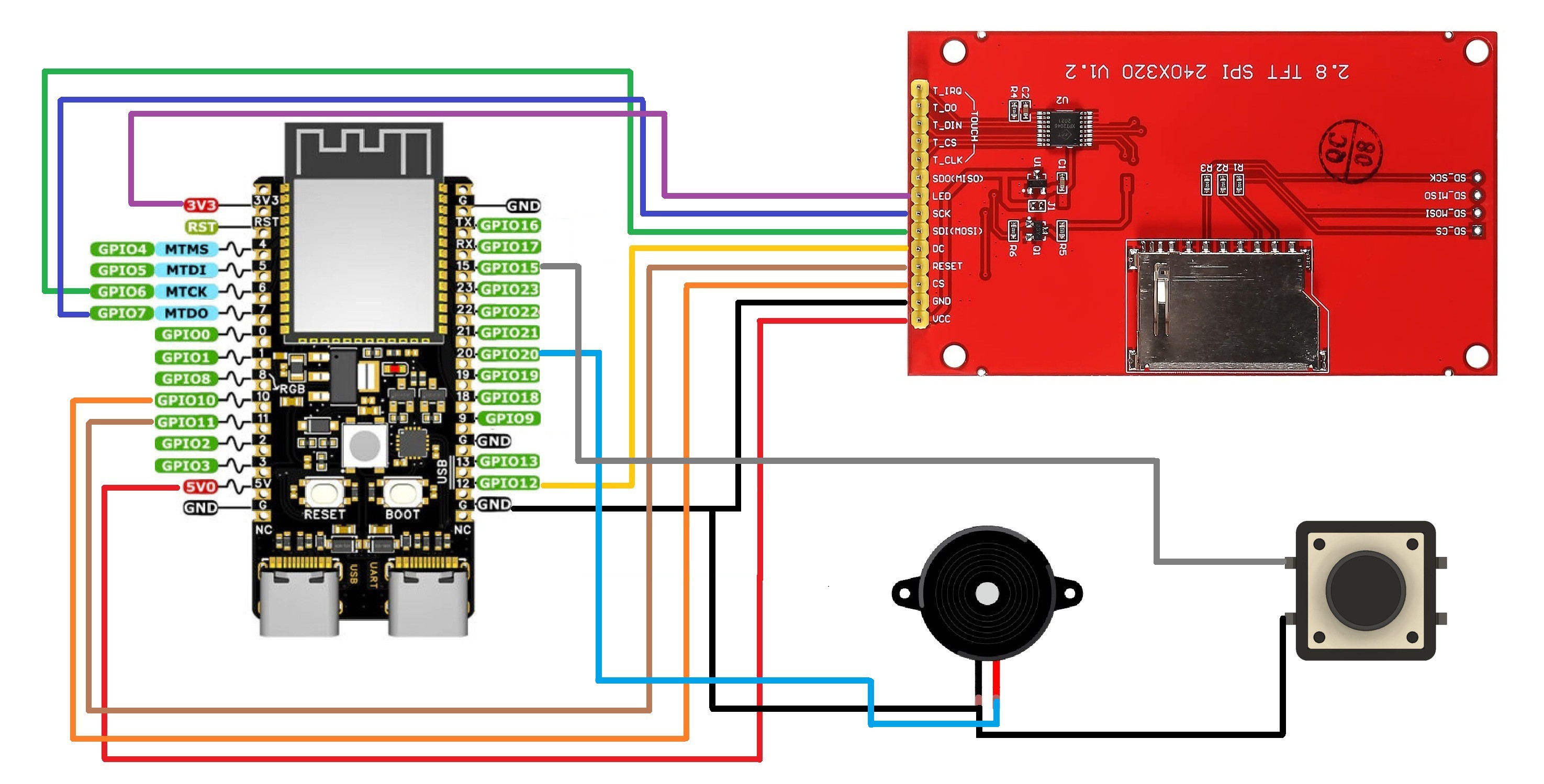
At its core is the ESP32-C6 Devkit, paired with an ILI9341 240×320 TFT display. For power, I built a custom circuit around the IP5306 power management IC, which steps up a 3.7V LiPo cell to a stable 5V which is enough to keep both the ESP and display running reliably.
The game logic is handled through a dedicated ESP32 library called BLEGamepadClient, which makes the Xbox controller pairing seamless. A buzzer adds tactile feedback when food is picked up, and a mode-switch button toggles between clock and game modes.
To bring the whole build to life, I designed an enclosure inspired by vintage 1980s television sets. The ILI9341 acts as the screen, framed by a retro shell complete with a dummy antenna and a 10-degree inclined base, a nod to old-school CRTs.
Materials Required
These were the materials we used in this project:
- ESP32-C6 Devkit V1
- ILI9341 Display
- Custom PCB (Provided by NextPCB)
- Buzzer
- Push Button
- Button PCB (Reuse from old Project)
- Connecting wires
- Breadboard
- XBOX Controller
- IP5306
- 10uF 1206 Capacitors
- 10K Resistor 0805
- Type C Port
- Vertical Push Button
- M2 screws
- Blue LED 0805
- 2R Resistor 1206
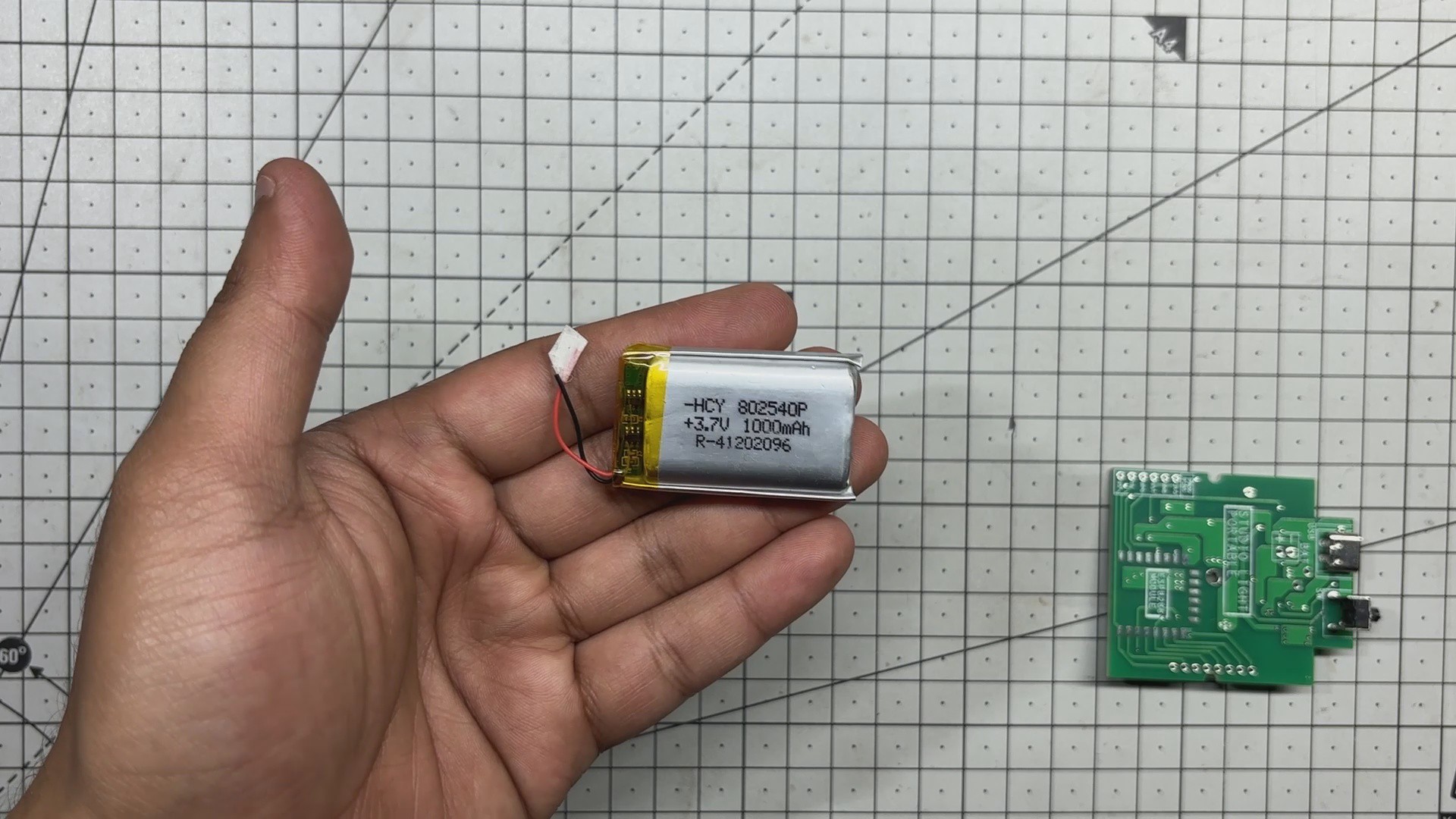
- 3.7V 600mAh LiPo Cell
- 3D-printed parts
XBOX Controller with ESP32—Initial Breadboard Setup
The idea to use an Xbox controller came from a project I had prepared earlier, where I demonstrated how to pair an ESP32 with the controller to perform various tasks. Initially, I used it to display button inputs on an ILI9341 screen.
https://hackaday.io/project/204381-xbox-controller-with-esp32
Once that concept was solid, I decided to repurpose the controller to drive one of my existing Snake game builds. I integrated BLE logic and input handling into the console code, and the result was a fully playable Snake game controlled via the Xbox controller’s left joystick.
For wiring, I followed a simple diagram that connects the ILI9341 display to the ESP32-C6 via SPI, along with a few additional GPIOs. The setup includes connections for a mode-switch button and a buzzer, making the entire circuit compact and easy to replicate.
CODE
Here's the code we used in this project and it's a simple one, we prepared this by using our previously created Internet Clock code and combining it with our previously made snake game console project code, this code we are using is a culmination of both projects combined into one.
#include <Arduino.h>
#include <WiFi.h>
#include <Adafruit_GFX.h>
#include <Adafruit_ILI9341.h>
#include <SPI.h>
#include <BLEGamepadClient.h>
#include <time.h>
// ------------------- Hardware -------------------
#define TFT_CS 10
#define TFT_DC 12
#define TFT_RST 11
#define TFT_MOSI 6
#define TFT_SCLK 7
#define BUZZER_PIN 20
#define MODE_BUTTON 15
#define LCD_WIDTH 320
#define LCD_HEIGHT 240
#define CELL_SIZE 8
#define GRID_WIDTH  (LCD_WIDTH / CELL_SIZE)
#define GRID_HEIGHT (LCD_HEIGHT / CELL_SIZE)
// ------------------- WiFi -------------------
const char *ssid = "YOUR SSID";
const char *password = "ADD PASS";
// ------------------- Display / Controller -------------------
Adafruit_ILI9341 gfx = Adafruit_ILI9341(TFT_CS, TFT_DC, TFT_RST);
XboxController controller;
XboxControlsEvent e;
// ------------------- Snake Game State -------------------
struct SnakeSegment { int x; int y; };
SnakeSegment snake[200];
int snakeLength = 5;
int dx = 1, dy = 0;
int foodX = 0, foodY = 0;
uint16_t foodColor = ILI9341_RED;
...
Read more »