Overview
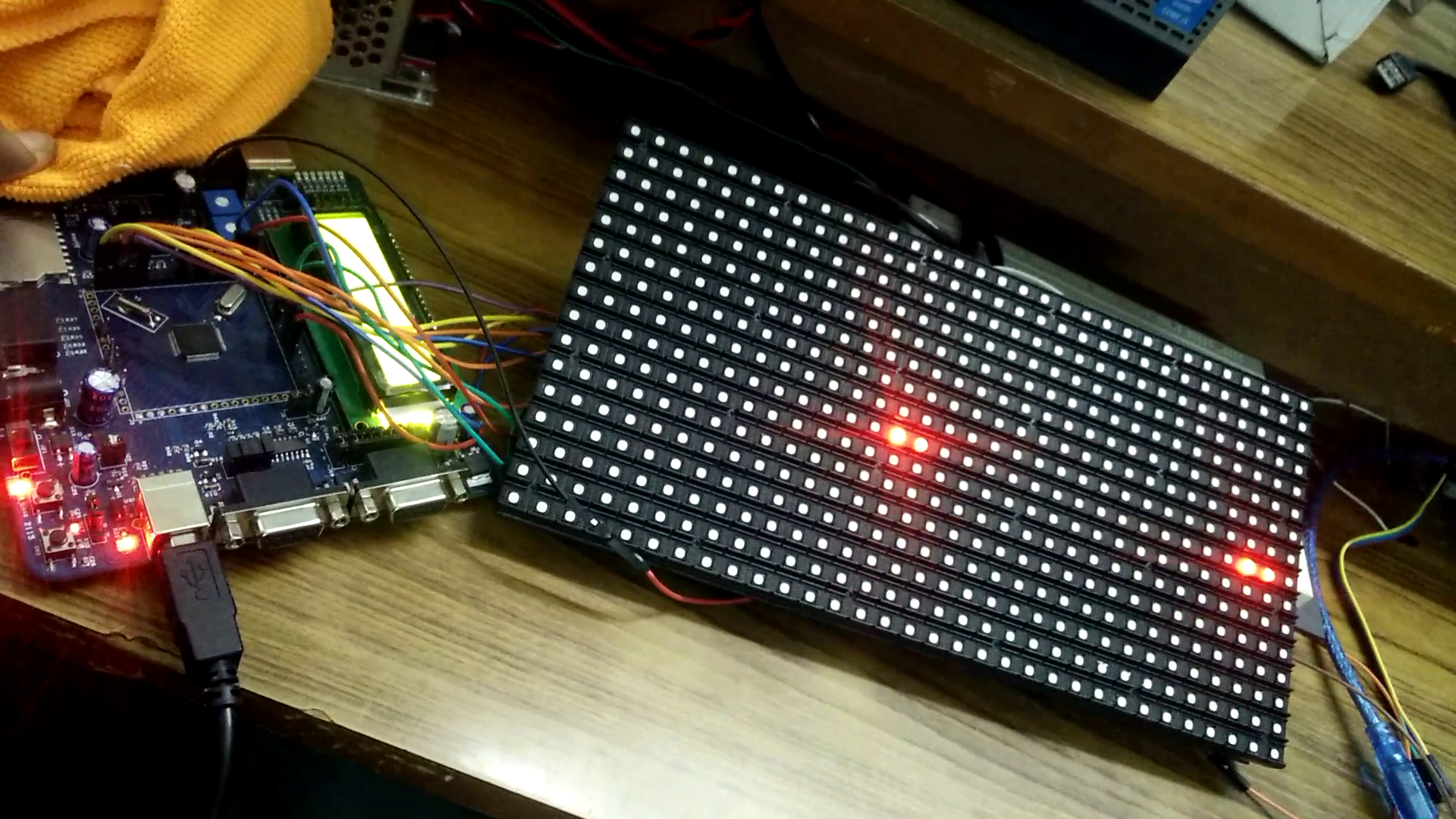
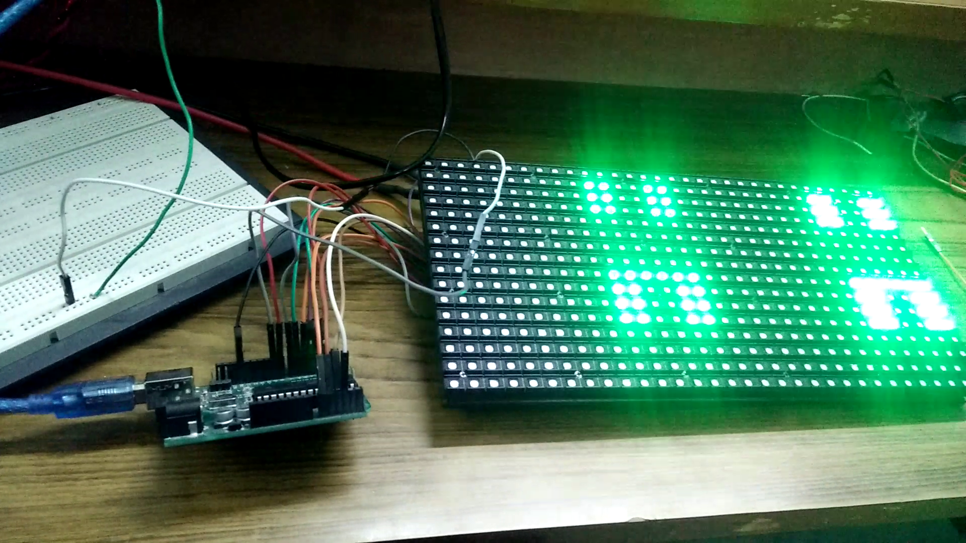
RGB LED matrix panels are used in commercial purpose such as advertising or to make video walls etc. We have used a HUB75 based 32x32(1024 LEDs) RGB LED panels in this project. This panel has 1/16 scan i.e. at a time 2 rows are selected for a given address.
Power Requirement
These panels require good 5V power supply, with at least 5A current capability. This panel running full tilt (all pixels set white), draws nearly 4+ Amps of current.
Pin Description
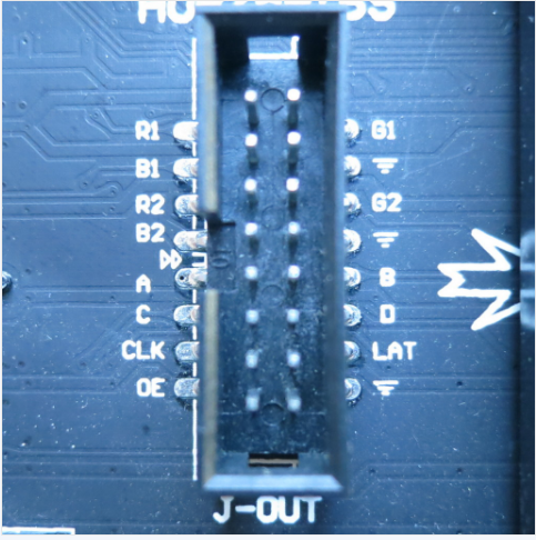
There are total 16 pins, 6 pins for R, G, B value, LATCH, OE, CLOCK, 4 pins for address selection and 3 pins are ground.
How the Matrix Works
- There are 1024 RGB LEDs in a 32x32 matrix. But all 1024 LEDs cannot be driven at once.
- One reason is that would require a lot of current, another reason is that it would be really expensive to have so many pins.
- Instead, the matrix is divided into 16 interleaved sections/strips. The first section is the 1st 'line' and the 16th 'line' (32 x 2 RGB LEDs = 64 RGB LEDs), the second is the 2nd and 17th line etc. until the last section which is the 15th and 32nd line.
- The reason they are arranged it this way is so that the lines are interleaved and look better when refreshed, otherwise we'd see the stripes more clearly
- For a single pixel to glow we have to feed 16 bits of data (4 bits for each R, G and B).
- The controller (say an FPGA or microcontroller) selects which section to currently draw (using A, B, C and D address pins – 4 bits can have 16 values). Once the address is set, the controller clocks out 32x2=64 bits of data and latches it. Then it increments the address and clocks out another 64 bits, etc. After doing this for four times the address is incremented. So the sequence in a nutshell is as below…
- Feed the rows
- Disable OE
- Enable Latch
- Increment address
- Enable OE
- Disable Latch
- The only downside of this technique is that despite being very simple and fast, it has no PWM control built in! The controller can only set the LEDs on or off. So what to do when we want full color? We actually need to draw the entire matrix over and over again at very high speeds to PWM the matrix manually. For that reason, we need to have a very fast controller, here we have used 60 MHz frequency to drive the panel.

 Richard Hogben
 Aleksei Tertychnyi