-
Current pattern video
11/28/2017 at 19:48 • 0 commentsThe video contains library files to drive an RGB Panel on LPC2148.
In this video we see a pattern where the blocks change color with time to showcase a capability of the panel to generate color.
Please note that the lines were generated due to some camera issue and were not visible with naked eyes. -
Pattern in main function
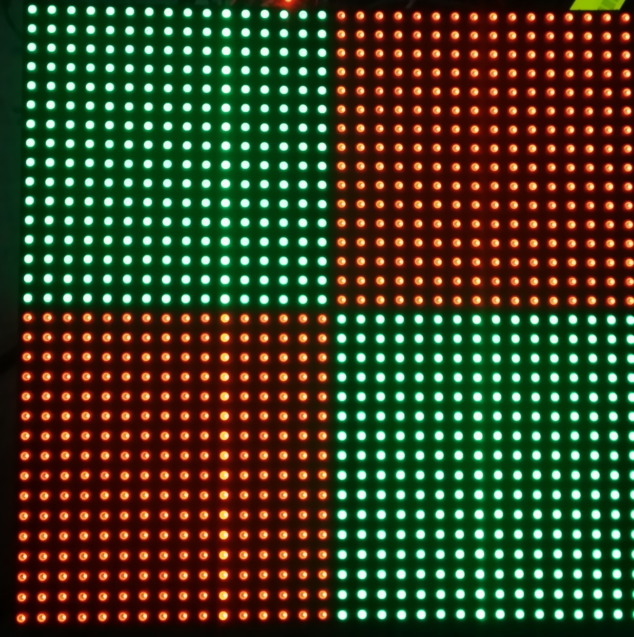
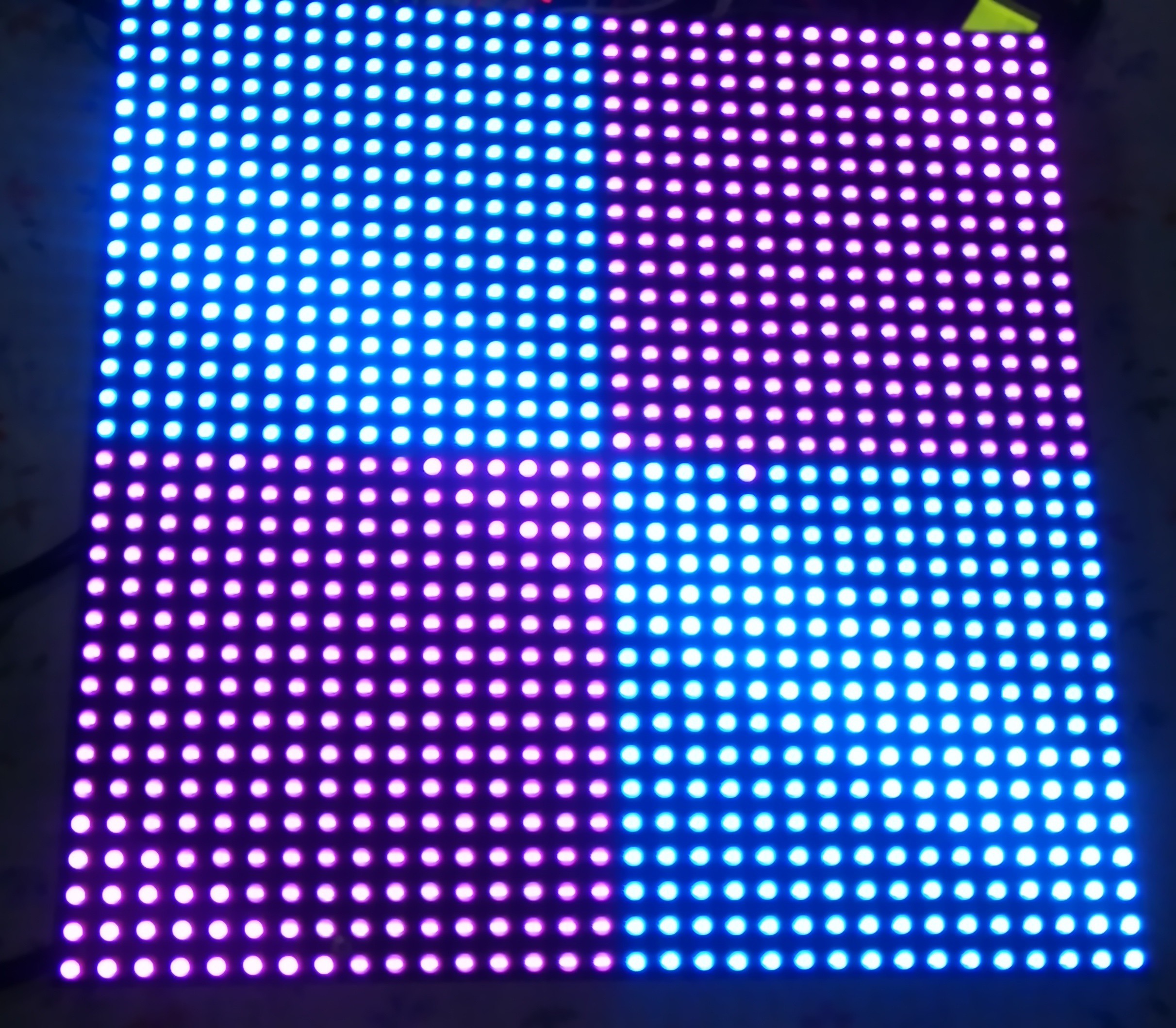
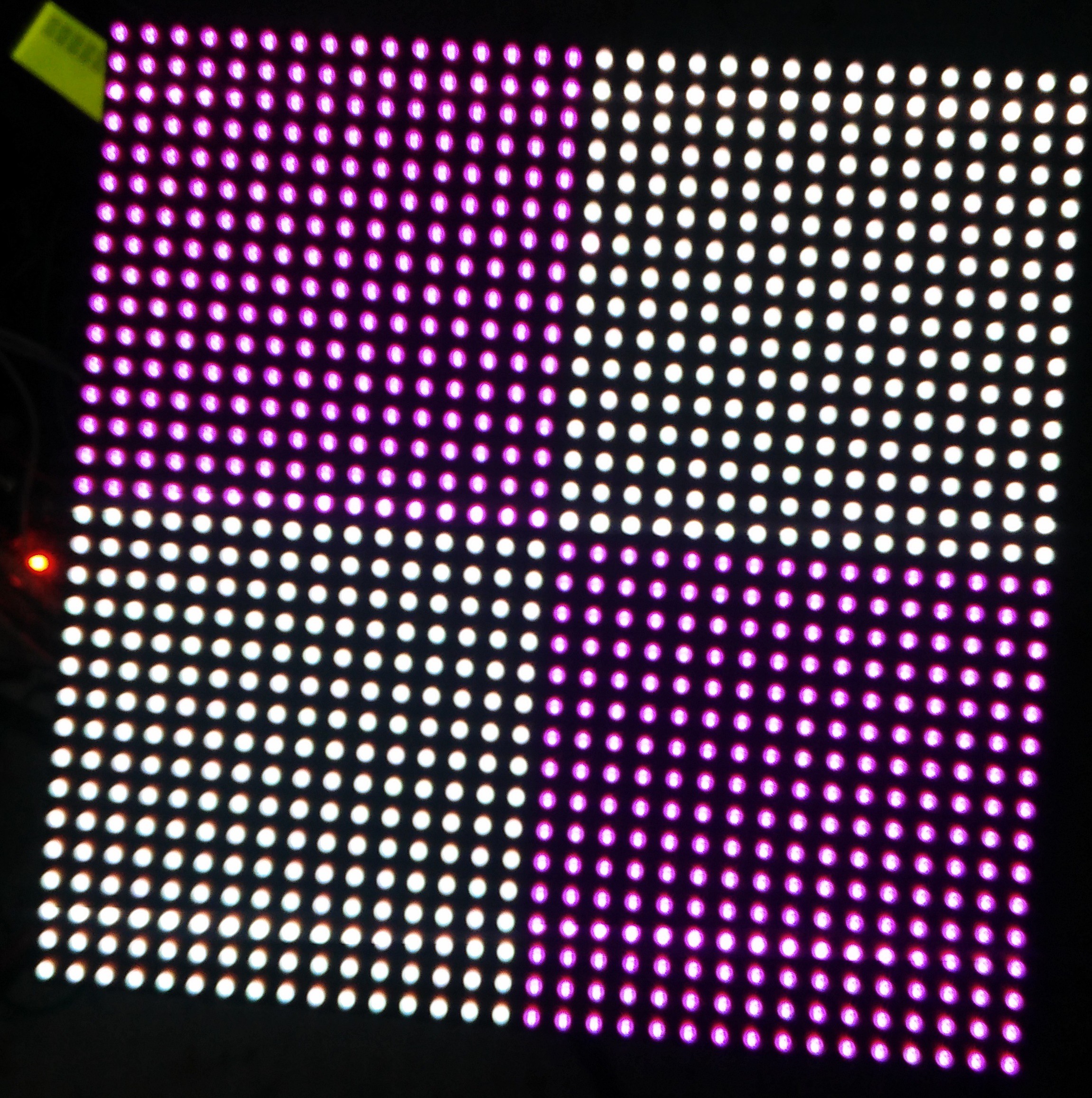
11/28/2017 at 19:38 • 0 commentsThe pattern brings up blocks of colors with time of various colors shown below.
The lines are not visible via naked eyes.
![]()
![]()
![]()
-
Making Headers
11/28/2017 at 18:37 • 0 commentsFollowing functions were created:
void activatepanel(void);
void initClocks(void);
void initTimer0(void);
void setupPLL0(void);
void feedSeq(void);
void connectPLL0(void);
void GPIO_Init_FAST(void);
void timerSettings(void);
void initializepanel(void);
void latch(int);
void setbitplane(int,int,int,int,int);
void drawpixelinit(void);
void drawpixel(int,int,int,int,int);
void drawverline(int,int,int,int,int,int);
void drawhorline(int,int,int,int,int,int);
void drawrect(int,int,int,int,int,int,int); -
Drawing a pixel
11/17/2017 at 16:47 • 0 comments![]()
__irq void timer0ISR(void){
long int readVal;
if(pixel<256){
if(pixel<3)
FIO0SET = 0x00040000; //rgb
else
FIO0CLR = 0x00FC0000; //rgb
FIO1SET = 0x00010000; //clock 1
FIO1CLR = 0x00010000; //clock 0
if((pixel==31)||(pixel==63)||(pixel==95)||(pixel==127)||(pixel==159)||(pixel==191)||(pixel==223)||(pixel==255))
latch();
}
else pixel=0;
pixel++;
readVal = T0IR; // Read current IR value
T0IR = readVal; // Write back to IR to clear Interrupt Flag
VICVectAddr = 0x0; // End of interrupt execution
} -
Running current files
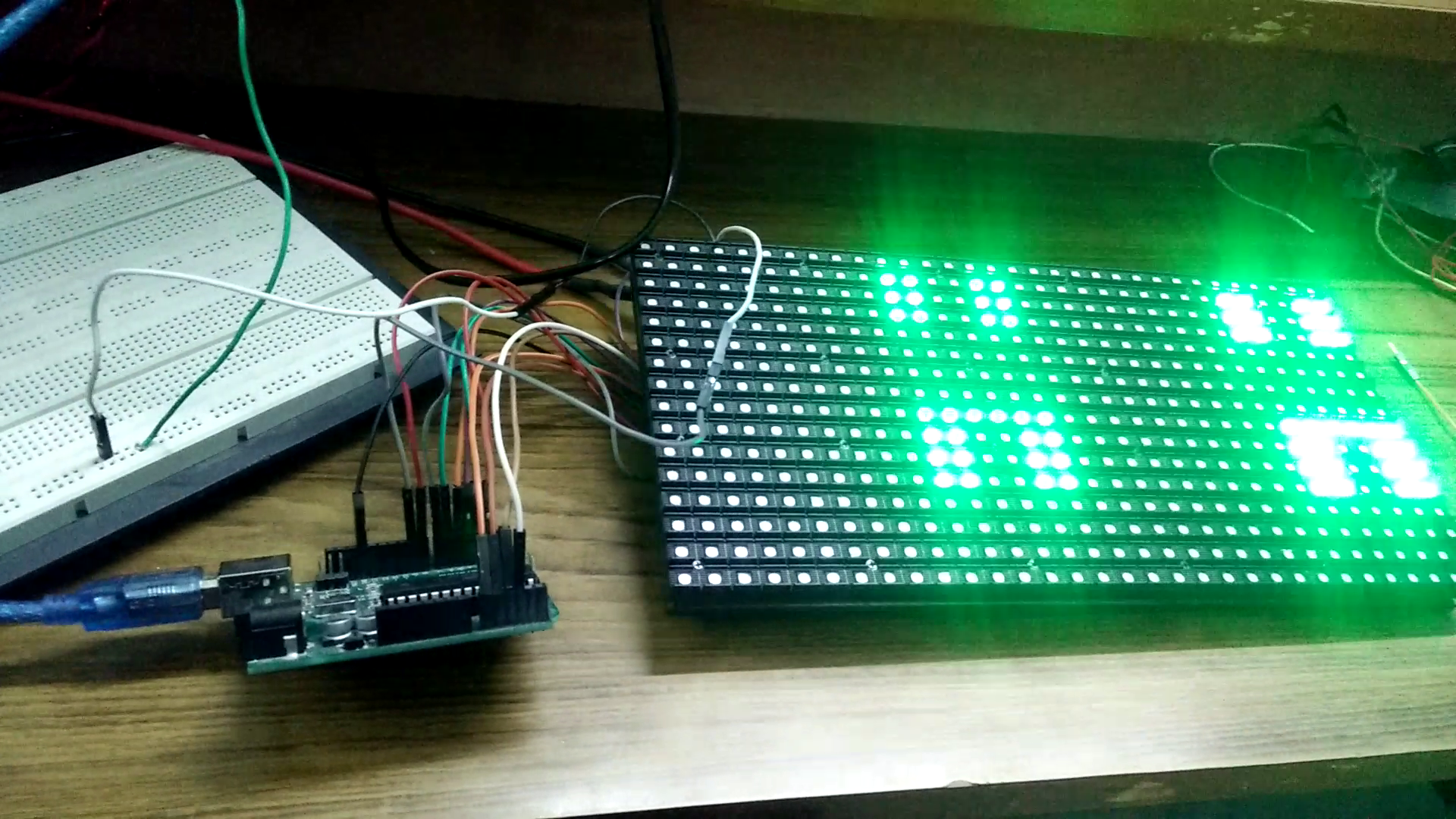
11/17/2017 at 16:18 • 0 comments![]()
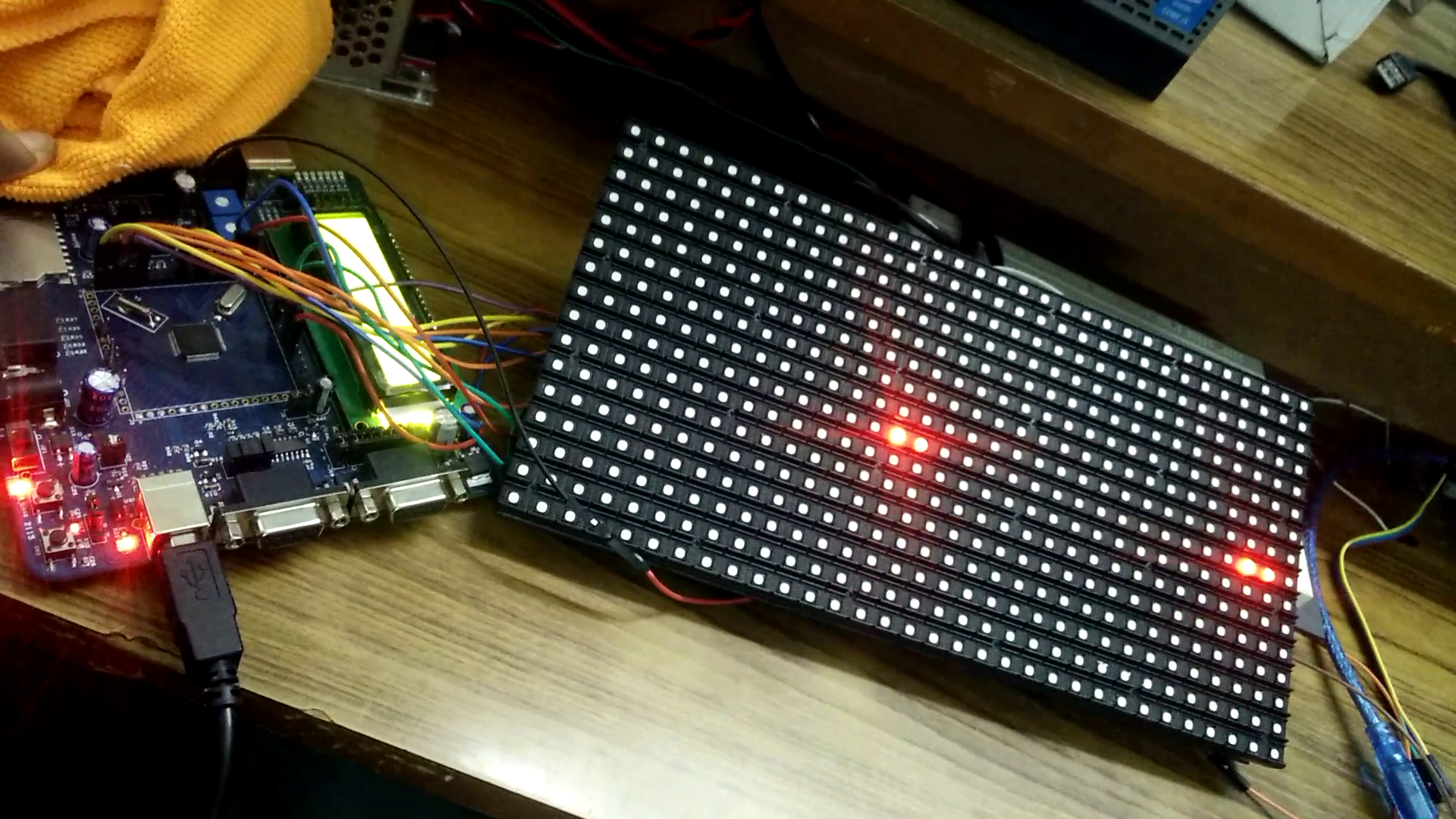
Running the LED panel on Arduino with library present in on the internet.
Scrolling "H" in a loop.
Does not work as per the video present in the link http://www.instructables.com/id/Arduino-UNO-Based-HUB75-LED-DISPLAY-DRIVER/Learning:
Arduino
Inline assembly code
Library files of LPC2148 for HUB75 Based RGB Panel
Library files of LPC2148 for driving graphics in HUB75 based RGB LED panels
