Neil K. Sheridan
-
#buildinstructions for hardware: PIR and camera
09/23/2017 at 18:28 • 0 commentsLet's get started on building this and writing the code! We'll do it in increments. So just check the parts, and skip to near the end if you don't want to bother with that.
1. Parts required for PIR and camera component of system
-- resistor[?]
-- Panasonic AMN14111 Pir Sensor 10m Long Range - Black (£15.39)
The datasheet for this is here: http://docs-europe.electrocomponents.com/webdocs/0030/0900766b80030a9d.pdf (PDF).
Rated operating voltage: 3V DC - 6V DC
Consumption current: 300 µA max
Output current: 100 µA
Output voltage: min = vdd -5 ; max = vdd - 0 (so same as operating voltage)
Stability time: min - 7s; max = 30s
* Need to be aware that whilst AMN14111 has digital output, some of the other AMNx series have analogue outputs. For instance those AMN2x are analogue output. Whilst AMN3x are digital again.
-- Female to female jumper cables x3
-- Raspberry Pi Camera V2 (IR-filtered)
NB. Yes, you might have noticed the PIR I used in the testing photos and videos wasn't the panasonic one! It really doesn't matter for demonstrating how to perform the testing!
2. Testing the PIR with a simple circuit
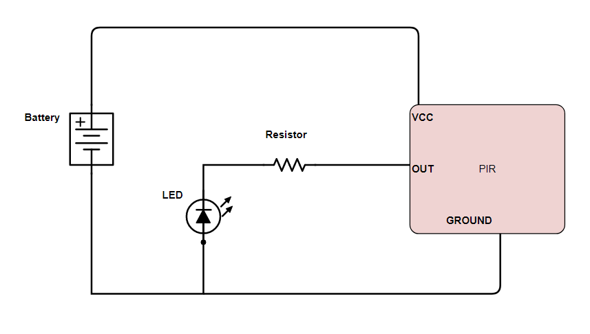
The following components were used for testing: breadboard, breadboard jumper wire, 300 Ohm resistor, visible wavelength LED, DC power supply (AA batteries summing 6v, in a battery holder with +ve and -ve connecting leads built-in, female to male jumper cables x3.
You could do it without a breadboard by stripping, and then just coiling the wires around the components I expect! Be careful with the PIRs because one of mine was broken in storage!
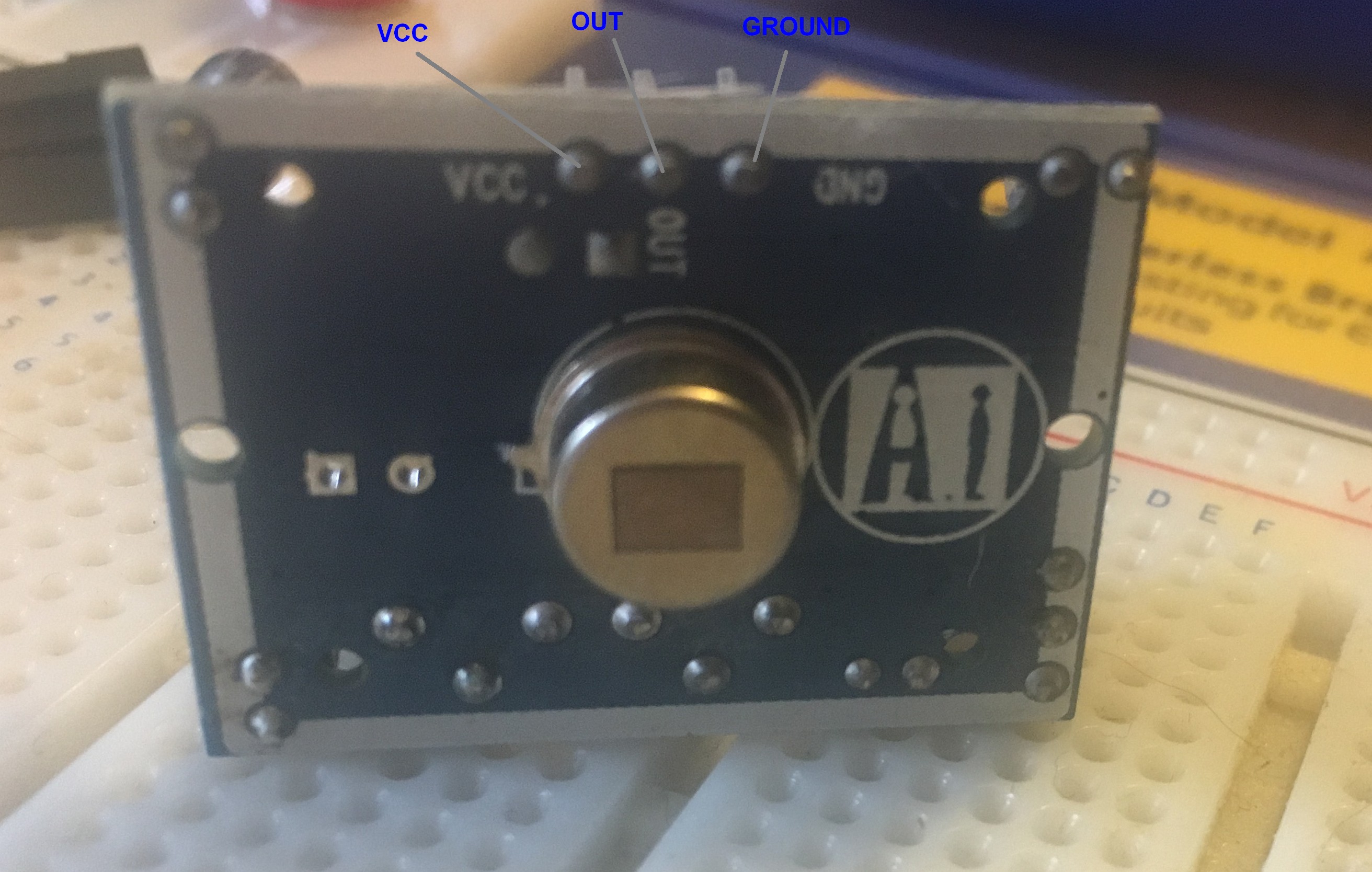
First of all inspect the PIR and determine which terminal is used for what! You can find the designations written on the front. You''ll have to gently remove the plastic lens to see them. There are three male terminals on a PIR: VCC, OUT, GROUND. The VCC takes the +ve voltage for power, whilst the OUT is signal out and will return high (e.g. 3.3V) when the PIR detects infrared (i.e. motion), ground is for ground -ve. There's a tutorial all about PIRs here -> https://learn.adafruit.com/pir-passive-infrared-proximity-motion-sensor/connecting-to-a-pir
![]()
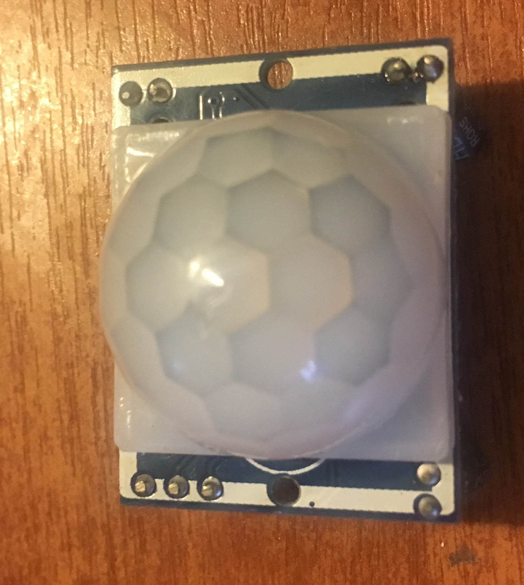
That's the sensor in the image above, with the designations of the terminals written at the top. In the image below you can see the plastic lens over the sensor.
![]()
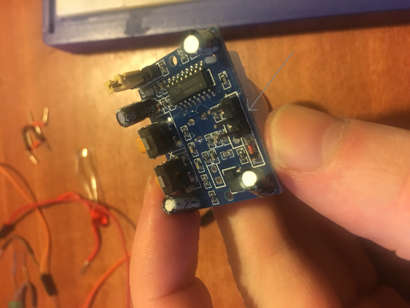
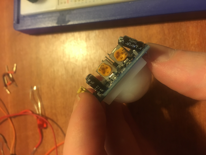
In the image below you can see the three male terminals for VCC, OUT, GND (GROUND). You need to connect your female ends of jumper cables to these. For the testing, we are using female to male jumper cables. So the male ends go into the breadboard.
![]()
Here's the circuit we need to build for the testing!
![]()
Now, once the PIR is connected to the circuit, we need to wait 60 seconds for the PIR to 'stabilize' - the LED might be on or blink for the first few seconds. Wait until it has been off for 60 seconds before putting your hand in front of the PIR for testing. Hopefully it all worked ok!
![]()
You can use the yellow trimpots for adjusting sensitivity of the PIR.
3. Connecting the PIR to raspberry Pi and basic code for testing
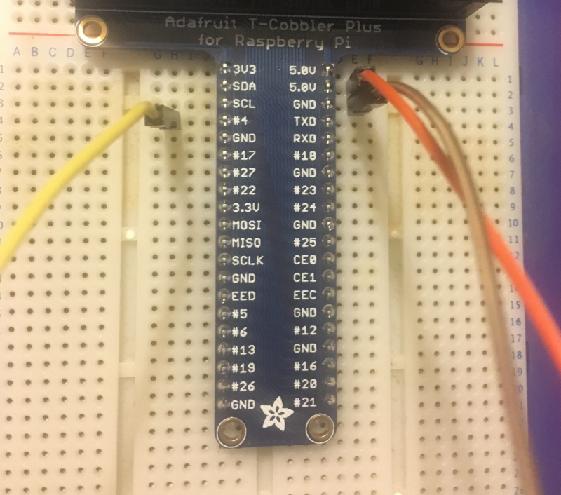
So now we need to connect the PIR to the Raspberry Pi. We need female to female jumper cables for this. That's if we are not adding a resistor again. If we do depends on the PIR. So, we connect VCC to 5v out pin on raspberry pi. We connect GND to a GND pin (ground). We can connect the OUT to any GPIO (e.g. GPIO4). In the below image, we are connecting the OUT for GPIO4. It's using the adafruit cobbler on a breadboard for ease of testing.
Remember the Raspberry Pi pins aren't marked on the board. The site https://www.raspberrypi-spy.co.uk/2012/06/simple-guide-to-the-rpi-gpio-header-and-pins/ has pin out diagrams for the Pi 3 Model B, and all the others.
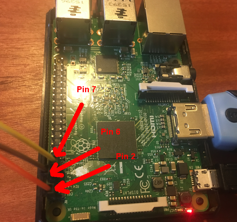
![]() Since you won't be using that in end - here are the connections shown to the actual pins on the raspberry pi. We've got the orange wire to pin 2 (5V out) for connecting to VCC on PIR. The brown wire is to pin 6 (Ground) for connecting the GND on the PIR. The yellow wire is to Pin 7 (GPIO4) input from the OUT on PIR. Pin 7 is on the column of pins closest to center of Raspberry Pi. Pins 6 and 2 are on the column closet to edge of Raspberry Pi. Remember if you are using BOARD numbering method you start counting pins from the end of board closest to the microSD card slot.
Since you won't be using that in end - here are the connections shown to the actual pins on the raspberry pi. We've got the orange wire to pin 2 (5V out) for connecting to VCC on PIR. The brown wire is to pin 6 (Ground) for connecting the GND on the PIR. The yellow wire is to Pin 7 (GPIO4) input from the OUT on PIR. Pin 7 is on the column of pins closest to center of Raspberry Pi. Pins 6 and 2 are on the column closet to edge of Raspberry Pi. Remember if you are using BOARD numbering method you start counting pins from the end of board closest to the microSD card slot.![]()
Here's some simple code to test the PIR is communicating correctly with the raspberry pi. So with this we'll get 0 printed whilst nothing is detected by the PIR, and 1 when something is detected by the PIR! Don't forget to let your PIR stabilise for 60 seconds first!
import RPi.GPIO as GPIO
import time
# import GPIO library & time library
GPIO.setmode(GPIO.BOARD)
# set mode as BOARD (vs. BCM) so we use the board numbering system for pins,
# in this case that would make GPIO4 = number 7 on the board (count and see!)
GPIO.setup(7, GPIO.IN)
# set number 7 pin on Raspberry Pi for input from the PIR out
try:
    while True:
        val = GPIO.input(7)
        # val variable gets either True or False depending if PIR
        # output is giving a voltage to pin 7 or not
        if (val == True):
            print("PIR DETECTED SOMETHING!!!")
        else:
            print("NOTHING HERE!")
            time.sleep(3)
            # wait 3 seconds
except KeyboardInterrupt:
    GPIO.cleanup()
    # clean up GPIOs
4. Test the PIR indoors in conjunction with the camera
So next we are going to use the PIR to trigger the raspberry pi camera.
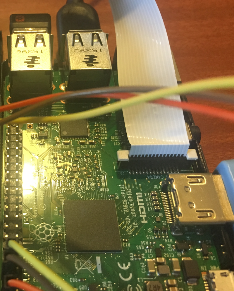
First, let's attach the Raspberry Pi Camera Module to the Raspberry Pi and check it works! Connect the flex cable from the camera to the CSI (camera serial interface) on the raspberry pi. It can be a bit fiddly and sometimes pops right out again - push it gently but firmly.
![]()
Now we can enter some testing code:
from picamera import PiCamera
from time import sleep
camera = PiCamera()
camera.start_preview()
sleep(10)
camera.stop_preview()
Don't forget to enable the camera is the operating system! You can do that from preferences -> raspberry pi configuration tool using your GUI. Or it can be done from command line with:
sudo raspi-config
The image acquired from the camera will pop up on your screen when you run the code!
Great! Now let's combine the PIR and the camera in some code. So when the PIR is triggered we acquire an image and save it to a file:
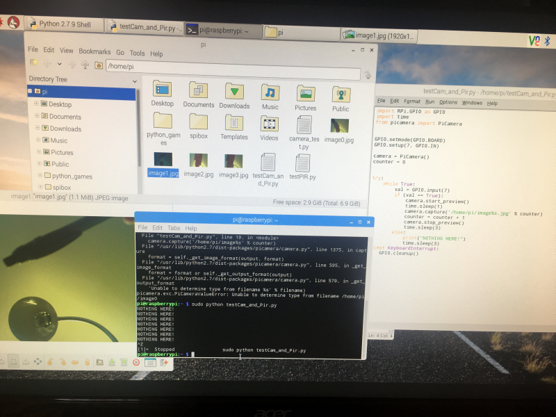
import RPi.GPIO as GPIO
import time
from picamera import PiCamera
GPIO.setmode(GPIO.BOARD)
GPIO.setup(7, GPIO.IN)
camera = PiCamera()
# assign PiCamera to our camera variable
counter = 0
# counter to zero
try:
    while True:
    val = GPIO.input(7)
    if (val == True):
    camera.start_preview()
    time.sleep(1)
    camera.capture('/home/pi/image%s.jpg' % counter)
    #capture image and write to file %s being counter so it's not
        #just overwriting the same file again and again
        counter = counter + 1
    camera.stop_preview()
    time.sleep(3)
 else:
    print("NOTHING HERE")
    time.sleep(3)
except KeyboardInterrupt:
    GPIO.cleanup()
Now you can see what happens when we run this! You can see the imagex.jpg files we got in the directory. And an example of one of the images (the camera was pointing up and I moved a pen over the PIR)
![]()
So, in the final version of the elephant detection device, we'll not work with that code. Instead we'll be wanting to take a certain number of images each time the PIR is triggered, then work with those (i.e. send them for classification, notify system users if they are classified as elephants, trigger deter devices), before going back to a loop to wait for the PIR to be triggered again.
That will look a little like this:
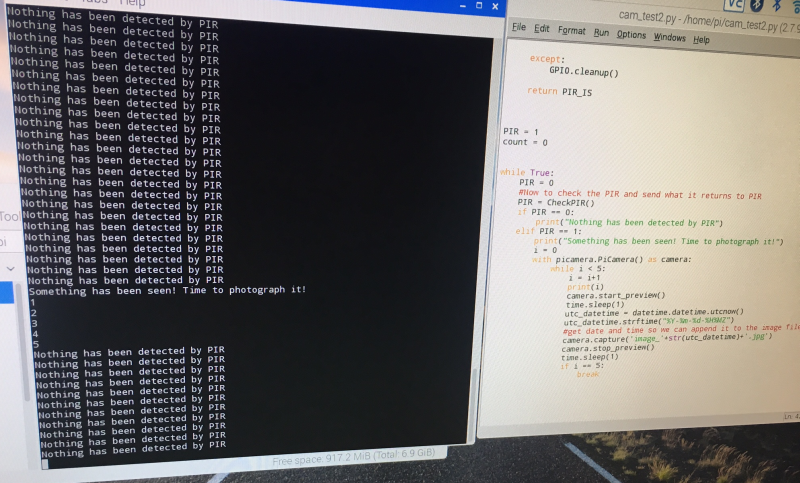
import time
import picamera
import datetime
import RPi.GPIO as GPIO

def CheckPIR():
    # dependencies are RPi.GPIO and time
    # returns whats_here with "NOTHING HERE" or "SOMETHING HERE"
    time.sleep(1)
    #don't rush the PIR!
    GPIO.setmode(GPIO.BOARD)
    # set numbering system for GPIO PINs are BOARD
    GPIO.setup(7, GPIO.IN)
    # set up number 7 PIN for input from the PIR
    # need to adjust if you connected PIR to another GPIO PIN
    try:
        val = GPIO.input(7)
        if (val == True):
            PIR_IS = 1
            #PIR returned HIGH to GPIO PIN, so something here!
        if (val == False):
            PIR_IS = 0
            #PIR returned LOW to GPIO PIN, so something here!
            GPIO.cleanup()

    except:
        GPIO.cleanup()

    return PIR_IS


PIR = 1
count = 0


while True:
    PIR = 0
    #Now to check the PIR and send what it returns to PIR
    PIR = CheckPIR()
    if PIR == 0:
        print("Nothing has been detected by PIR")
    elif PIR == 1:
        print("Something has been seen! Time to photograph it!")
        i = 0
        with picamera.PiCamera() as camera:
            while i < 5:
                i = i+1
                print(i)
                camera.start_preview()
                time.sleep(1)
                utc_datetime = datetime.datetime.utcnow()
                utc_datetime.strftime("%Y-%m-%d-%H%MZ")
                #get date and time so we can append it to the image filename
                camera.capture('image_'+str(utc_datetime)+'.jpg')
                camera.stop_preview()
                time.sleep(1)
                if i == 5:
                    break
GitHub: https://github.com/nksheridan/elephantAI/blob/master/demo_Take_Photo_when_PIR_high.py
So first of all we put our PIR code into a function, checkPIR(). That goes and returns a variable called PIR_IS. This has 0 in it if the PIR doesn't detect anyway, and 1 if it does!
Then we set up a while True loop, so this just keeps on going. The first thing we do that is call our checkPIR() function and put the value it returns (0 or 1) into a variable called PIR.
Next we have an if PIR == 0, so if that's true then we didn't detect anything.
Now we have an if PIR ==1, so if that's true then we did detect something! And we go ahead to capture images. Here we are getting 5 images. So let's assign PiCamera as camera. And set i as 0; i is going to be our counter for the number of images we've taken.
Right! We've got a while i < 5 loop now. So we keep taking images until we get 5 of them! First thing we do in that is increment i with i = i + 1 to keep track of how many images we have.
Then we warm up the camera with camera.start_preview()
Next, we can use utc_datetime to get the date and time. We will append this to the end of our image filename.
Now we use camera.capture to capture an image and store it as image_dateandtime.jpg
Ok, let's run the code, and we can test it by putting our hand in front of the PIR! Here's the kind of output we get:
![]()
5. Testing the PIR and camera indoors with a cat feeding station [not done]
Here we'll go ahead and show how to add a reset button and a safe power-down button. And we'll power the Raspberry Pi from a LiPo battery with the RPI PowerPack V1.1 (specifications here: http://www.raspberrypiwiki.com/index.php/RPI_Lithium_Battery_Expansion_Board_SKU:435230). I was going to add using tensorflow to detect cats too, but I'm probably running out of characters for my log! So I'll do that in another one instead. It's fun if you've cats and dogs in your house and Kaggle had a competition about this too. So everything is easily available: https://www.kaggle.com/c/dogs-vs-cats/data
6. Testing the PIR and camera outdoors [not done]
Here we'll get everything in a waterproof case, and put it outdoors. Hopefully we should spot some birds, more cats, and anything else that moves in your garden/yard. I'll add Twython code so the images can be uploaded to twitter.
That's about it for the testing iterations of the PIR and camera part of the ElephantAI system. Next it would be builds for various enclosures and the build for the entire ElephantAI detection devices.
It might appear a bit over-simplistic for me to add all these build instructions, including even an LED and PIR circuit with a battery! But people who are deploying the ElephantAI system might not have any experience of electronics at all! So we want to start from the basics and work up with these iterations.
====
What I'm going to do is add build instructions for using commonly available enclosures for PIR and camera mounting. Such as ModMyPi (£16-£26), the SPi-Box (which is fairly low-cost e.g. £13 on Amazon). Then I'll go through just using a couple of random enclosures and cutting holes in them. In addition, how to go ahead and mount the commonly available enclosures into a waterproof enclosures. Then I'll detail the build instructions for the entire detection device in one enclosure. I'll do this in another log. The whole idea of the elephantAI system is to be flexible, thus utilizing whichever materials are easily available!
I'm not sure if to offer a 3d printed solution - just because it is going to be more expensive than buying ABS enclosures. For instance, you could go on ebay and find a 200x120x75mm ABS enclosure that is IP65 rated (IP65 is no dust ingress and protected against low pressure water jets from any direction. Limited ingress permitted.) for £6. Then adding grommet seals, plastic eyelets, etc. to any holes you've cut + glue!
======
-
Mobile connectivity
09/22/2017 at 20:14 • 0 commentsWhich hardware can we use to get mobile connectivity per 2G/3G/4G for our devices?
1. Huawei E182E/E173 USB dongles
So I looked at these first for 3G and below connectivity. They're fairly low-cost e.g. I got one for £30, but they're also fairly icky to use! The Rasp Pi doesn't like powering them and you tend to need a USB hub instead; and they keep getting treated as USB storage instead of a modem. Some of the issues and solutions are outlined here: https://flyingcarsandstuff.com/2014/11/reliable-3g-connections-with-huawei-e182ee173s-on-raspberry-pi/ // I'll make a post about it myself later, as this will be one of the possible connectivity solutions we'll be using.
2. Adafruit FONA 808 - Mini Cellular GSM + GPS Breakout
Ok, this is great and it's only ~£50. But I can't get a 2G SIM in the UK for it! We can send out SMS with it, and we can send/receive GPRS data (TCP/IP, HTTP, etc.), has GPS. Thus can send our alert messages to either twitter, or a server. It's also voice, so perhaps could send out audio files to voice as alert warning method? I hadn't considered that until now. Anyway, it'll be great in places with a 2G network.
3. SIM5215E 3G/GPRS shield over Arduino and Raspberry Pi
So with this we've got SMS, voice (again possible to send audio files like this?), GPRS, and 3G. They've got code all ready for FTP/FTPS, HTTP/HTTPS, TCP/UDP! So that's really great! The only problem is that it costs 250 euros! And this SIM5215 doesn't even have GPS.
Code examples/manual: https://www.cooking-hacks.com/documentation/tutorials/3g-gps-shield-arduino-raspberry-pi-tutorial/
https://www.cooking-hacks.com/3g-gprs-shield-for-raspberry-pi-3g-gps
Frequency coverage:
SIM5215A
Dual-Band UMTS/HSDPA 850/1900MHz
Quad-Band GSM/GPRS/EDGE 850/900/1800/1900MHz
Output power: UMTS 1900/850: 0.25W
SIM5215E
Dual-Band UMTS/HSDPA 900/2100MHz
Tri-Band GSM/GPRS/EDGE 850/900/1800MHz
Output power: UMTS 2100/900: 0.25W
I'll need to check these against which we'll have in the countries the system is intended for!
4. Altitude Tech IOT BIT 3G HAT for the Raspberry Pi – UK, EU & Asia region
This one looks promising! We've got 3G again, and SMS, but we've also got a GPS. And we've got our frequencies in other countries covered. Well hopefully. And this one is a more reasonable £166.66. Note, it uses nanosim.
Info: https://hackaday.io/project/25925-pianywhere-4g-lte-hat-for-the-raspberry-pi and http://www.instructables.com/id/PiAnyWhere-4G-LTE-Hat-for-the-Raspberry-Pi/
5. Adafruit FONA 3G Cellular + GPS
Ok well, it's 3G, voice, SMS, and GPS too. Unfortunately the library is under heavy development - so we would kind be on our own at the moment with this. It's £80. Details here: https://learn.adafruit.com/adafruit-fona-3g-cellular-gps-breakout/overview
SUMMARY
The Altitude Tech one sounded good, but I was a bit put off by lack of code examples, and some negative comments from users re support on instructables.com. And now I've found out there is 60 euros tax on the SIM5215E; this brings it to 350 euros w shipping! That's really too expensive! So I'm a bit stuck! I'll probably try the Adafruit Fona 3G and see how I get one with that for now.
-
Switching between raspberry pi depending on lighting (day/night)
09/21/2017 at 19:59 • 0 commentsNow, if everyone recalls. There are two conditions under which we will be spotting elephants: daylight condition and night condition. In the first condition we use the IR filtered camera, in the second we use the NoIR filtered camera with IR illumination from LED array. Hence we need two raspberry pi's each having either NoIR or IR-filtered camera. Since we can't multiplex. I did think we could, but I noticed one of the raspberry pi engineers saying it was very complicated and not worth it. So we are stuck with a more clumsy solution.
So it's easy to use hardware to detect if it's daylight on night condition. Just with a digital sensor such as Adafruit FLORA Lux Sensor - TSL2561 we'd get HIGH or LOW depending on the lux.
Right well, so raspberry pi 1 (daytime) can have at the start of its loop 'is that sensor giving me HIGH for daytime lux or is it giving me LOW for night?'. ' If it gives me LOW I'll break out of the loop and run the code after that'.
The code after that putting raspberry pi 1 as a server (using SocketServer). Raspberry pi 2 was already waiting as a client. So now raspberry pi 1 can send a command to raspberry pi 2 'it's time for you to break out of your client waiting loop and take over from me' since it is night condition now and we want the raspberry pi 2 with the NoIR and IR illumination LED array to start spotting elephants.
I guess we can put raspberry pi 1 into another loop now which is just watching for HIGH or LOW on the TSL2561 sensor. Once it gets HIGH it can say 'hey raspberry pi 2 (client) you are done with that loop. Break out of it and just go back to listening on your socket xxxxx until I tell you it's time to take over'.
Note: well, it's maybe not entirely clear what I mean. But that's my first thought on how to do it! I'll update when I get to this!
Of course, we don't need the two raspberry pi's to communicate at all in an alternative scenario. They can both have respective lux sensors. The daytime raspberry pi beginning its loop when its sensor gives HIGH (stop on LOW), and the night raspberry pi beginning its loop when its lux sensor gives LOW (stop on HIGH). Presumably we can share the mobile connectivity hardware. Or in worst/ least-elegant case ,they'd each have their own.
-
Messaging formats: example of JSON alert message file
09/21/2017 at 19:09 • 0 commentsHere's what the JSON alert message file looks like:
{ "spotted" : "True", "time" : "0000", "date" : "Today", "location" : "At the back of field 10 near the stream", "latitude" : "000", "longitude" : "000", "details" : { "lonemale" : "no", "herd" : "no", "calves" : "no" }, "deter" : { "deterdone" : "no", "deteraudio" : "no", "deterphysical" : "no" }, "battery" : "value" } -
Messaging formats: Dumping JSON alert message to file
09/21/2017 at 19:03 • 0 commentsHere I've got the variables obtained from the detection device (e.g. was an elephant detected, what kind, time, location of detection device, etc) and I dump them to the JSON format file. We can go ahead and send this file to the deter device, or upload it to a server. If you've been reading the updates you'll realise I gave up on using XML!
# Here we write the values of variables  we've obtained to our JSON
# elephant alert
# message file
import json
#the variables with dummy values
spotted = "Yes"
time = "0130"
date = "01/10/2017"
lat = "-11111111"
lon = "-00000000"
lonemale = "yes"
herd = "no"
calves = "no"
deter_sent = "yes"
audio_deter = "yes"
physical_deter = "no"
batteryvoltage = "12"
#getting them into JSON format
data = {
    "spotted" : spotted,
    "time:" : time,
    "date" : date,
    "latitude" : lat,
    "longitude" : lon,
    "details" : {
        "lonemale": lonemale,
        "herd": herd,
        "calves": calves
        },
    "deter" : {
        "deterdone" : deter_sent,
        "deteraudio" : audio_deter,
        "deterphysical" : physical_deter
        },
    "battery" : batteryvoltage
}
#writing them to JSONelephants.json JSON file
with open('JSONelephants.json', 'w') as f:
    json.dump(data, f)
I did rather question the whole concept of actually storing our variables in JSON-format alert message files after I finished up doing it! Why not just send the variables themselves to the web server, SMS, twitter? That's fine for twitter and SMS, but I figure uploading the JSON to the server is going to save a bit of code. Hopefully!
-
Messaging Formats: Parsing JSON alert message
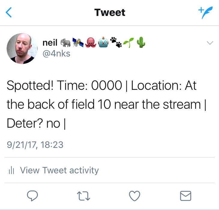
09/21/2017 at 18:59 • 0 commentsHere I've got an example elephant detection alert message in JSON format that I import, parse/de-serialise, then it's ready to be sent out to system users via either SMS, or twitter (as is shown here):
#working with elephant alert messages using JSON
#version 1.0 (21/9/2017)
# JSON represents data as nested "lists" and "dictionaries"
# unlike XML which is trees
import json
#open the json file
with open('elephants.json', 'r') as f:
    data = json.load(f)
#printing out all the values from the json for debug purposes
print 'Spotted:',data["spotted"]
print 'Time:',data["time"]
print 'Date:',data["date"]
print 'Location:',data["location"]
print 'Lat:',data["latitude"]
print 'Lon:',data["longitude"]
print 'Lone Male?:',data["details"]["lonemale"]
print 'Herd?:',data["details"]["herd"]
print 'Calves?:',data["details"]["calves"]
print 'Deter done?:',data["deter"]["deterdone"]
print 'Audio deter?:',data["deter"]["deteraudio"]
print 'Physical deter?:',data["deter"]["deterphysical"]
print 'Battery voltage:',data["battery"]
# here we can de-serialize the fields ready  for sending out to system
# users via SMS, twitter, etc  or working with the values for something else
# remember that the deter devices, and the web server/server will be
# sent a copy of the JSON file we put together earlier.
#location, time, date, lat/lon
spotted = data["spotted"]
# yes or no for spotted which is maybe a bit redundant since we wouldn't
# get an alert if it was "no"!
location = data["location"]
time = data["time"]
date = data["date"]
latitude = data["latitude"]
longitude = data["longitude"]
# no point in doing if else etc here since it could be all of them!
# elephant details
lone_male = data["details"]["lonemale"]
herd = data["details"]["herd"]
calves = data["details"]["calves"]
#deter details
deter = data["deter"]["deterdone"]
audiodeter = data["deter"]["deteraudio"]
physicaldeter = data["deter"]["deterphysical"]
#battery status
batteryvoltage = data["battery"]
## Sending these out to twitter using Twython
from twython import Twython
# Put the required variables into our twitter message
# i.e. in this example time, location, and if deter occurred
message = "Spotted! Time: %s | Location: %s | Deter? %s |" % (time, location,
deter)
C_KEY = 'xxx'
C_SECRET = 'xxx'
A_TOKEN = 'xxx'
A_SECRET = 'xxx'
api = Twython(C_KEY, C_SECRET, A_TOKEN, A_SECRET)
api.update_status(status=message)
Here's our tweet that resulted!
![]()
We may instead send via DM for security reasons. That's accomplished with the following code:
api.send_direct_message(screen_name="name",text=message)We can also upload the photo which contains the detected elephant to twitter using Twython too! But that is probably not required, and may constitute a security issue related to giving information on location to poachers.
-
Messaging formats: what should be sent to who?
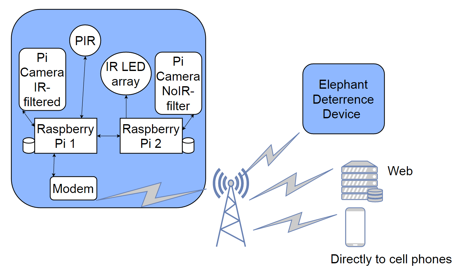
09/20/2017 at 18:04 • 0 commentsSo, I've been deciding which format we should use to store the observations made by the detection devices, and for 'on the wire' message format per communications between detection devices, deter devices, web server, twitter, mobile phones.
Let's look back at the system architecture:
![]()
We are going to be sending messages to:
1. Elephant deterrence devices (full message)
2. Web server (full message)
3. Mobile phones (SMS, so just some fields extracted from message)
4. Twitter DMs (full message)
Here's what I've got in XML for the message format:
<elephantalertmessage>
 <spotted></spotted>
 <location></location>
 <latitude></latitude>
 <longitude></longitude>
 <date></date>
 <time></time>
 <batterystatus></batterystatus>
 <spottingdetails>
   <herd></herd>
   <lonemale></lonemale>
   <calves></calves>
   <tusks></tusks>
   <musth></musth>
 </spottingdetails>
<deter>
  <performdeter></performdeter>
  <audiodeter></audiodeter>
  <physicaldeter></physicaldeter>
 </deter>
</elephantalertmessage>
I know I've written it in XML, but I might go ahead and use JSON instead - since that's a lot easier to work with in python. I'll see how I go on. I didn't get on too well with XML today!
Anyway so, either XML or JSON can be stored as file after we finish we detecting and get all our variables back.
<performdeter> would be determined for each device and hard-coded in by the users. For instance, if there was no deter device nearby we wouldn't want true for this. And if it was an elephant path we wouldn't want deter to be true! However, a crop field placed device would want this value as true. Same kind of thing for deter type i.e. <audiodeter> and <physicaldeter>
The <location> is tricky. There are several ways to approach this:
- Simply device number is reported. Here system users would have to recall from memory where this device resides (" oh yes number 10 is on the elephant path near to where they exit the forest") if the message is coming via SMS. If it's coming via device -> server -> mobile gateway -> mobile phone then we could have a lookup table on the server. This would match device numbers to Lat/Lon physical locations. The lat/lon can be given to Google Maps API to provide users with a map showing the location. In this scenario, users would have to update the lookup table whenever devices were moved.
- Each device has a GPS. In this scenario we can include the <latitude> and <longitude> in messages via SMS and via device -> server -> mobile gateway -> mobile phone, or device -> 3G/4G -> twitter DM. Obviously giving a lat/lon via SMS e.g. Lat=19.075984, Lon=72.877656 is not going to be very helpful! But we can go ahead and use the Google Maps API to give mapping if we are sending this via the device -> server -> mobile gateway -> mobile phone pathway. So the main advantage of each device having GPS is that we don't need a lookup table and system users don't need to worry about updating such a table themselves. They can move the devices around as they wish.
To be honest, maybe it is getting a bit over-complicated. A lot of the time I think we will have a low-connectivity scenario, so we'll only be having SMS available. We could actually make the <location> a bit more useful by keeping the devices static and having a string for each that we put into location e.g. "this is the one at top of Aadesh's biggest field near the forest" or "this is the one on the elephant path when they exit forest to reach the water".
So we'd parse the following from XML/JSON we made, for sending out via SMS:
<spotted>
<location>
<date>
<time>
<spottingdetail>
<deter>
<batterystatus>
___
Just a note, that I'm thinking of after we've triggered a deter device! Should the deter device message the detect device and say done=true, then detect device can be thinking if we didn't get another <spotted> as true within 360s then deter was successful!
-
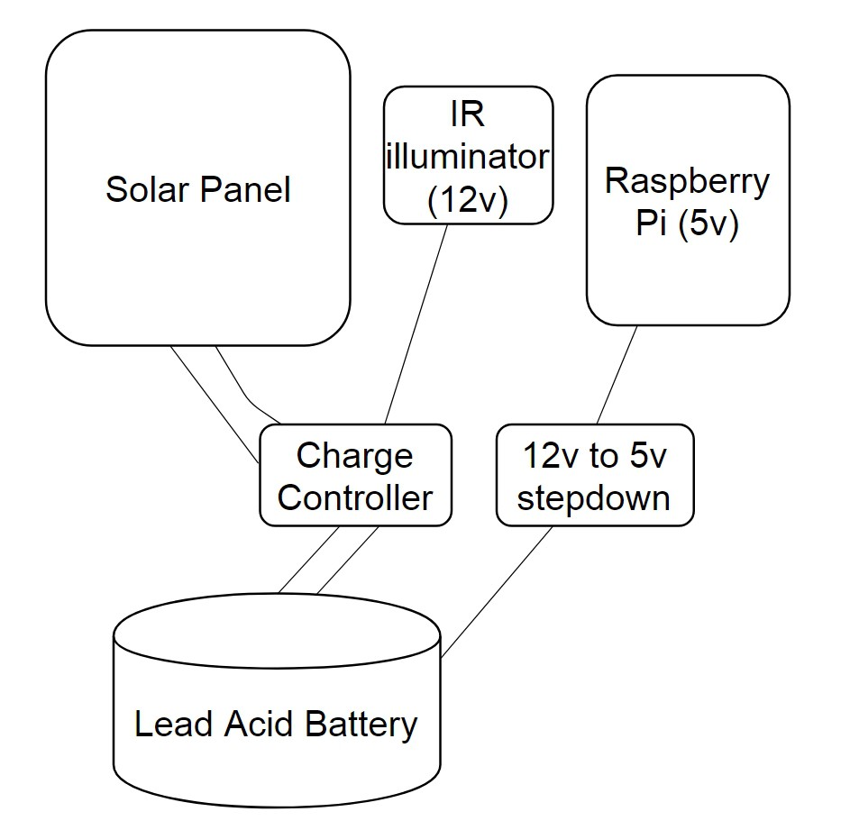
Solar charging and power supply
09/19/2017 at 20:26 • 0 commentsWe can't have people coming and changing batteries or charging LiPo's each day! So the devices need to be solar charged! Here's what I'm working on now:
![]()
SOLAR PANEL
What is the output power of the solar panel we need?
First we need to determine the total energy usage of the device in 24hr period (Watts). We can put this into the following equation as E. Whilst the output power of solar panel is P(solar). Let's supply the total time solar panel is in direct sun as 10hrs
P(solar) = E / (10*60*60)
BATTERY
Now how long do we need the battery to be able to deliver energy without solar charging? Obviously this is all kinda rough. We can go ahead and use a solar insulation map to determine more exact number of hours solar panel is in direct sun at a given time in year. So let's say anyway, we want the battery to deliver 48hrs of energy without any charging:
C(battery) = E / V*60*60
Where V = voltage we need, and C(battery) = storage capacity in Ah, and E = energy usage of device.
WIRES
To connect the solar panel to the charge controller, and the charge controller to the battery, and the charge controller to the IR illumination device, and (not shown) to the elephant deter devices, I'll use 18 AWG Gauge Electrical Wire.
SUMMARY
I'm yet to calculate E with any accuracy. So I can't say what output power solar panel I need. I've actually got a 30 watt solar panel at the moment which cost £40. It would be great to find I only need a lower cost 5W! As per battery, we need 12v for the IR illumination. We'll step down from that for the raspberry pi. I'm thinking of 7Ah 12v at the moment. I'm a bit worried about the cost of charge controllers really. The whole idea of these is to protect against reverse current flow from battery to solar panel (e.g. a diode), and to prevent overcharging the battery (that seems a whole lot more complicated than protecting against reverse current flow!).
N.B. I'm aware overcharge is a big issue! Especially if you've got these batteries in a forest and it is dry. We certainly don't want a fire! So off top of head re charge controllers: these will have their own micro-controller to monitor reverse current flow, temperature. Protection is going to vary according to the battery chemistry for over-charge. Like a guess you can use a regulator to prevent overcharging?
Update:
Well, as regarding charge controllers! I've found this one:
![]()
which actually seems to have a step-down to 5V! So I'll have a look at that since it's only £16 "
HQST 10 Amp 10A PWM Smart Solar Charge Controller 12V/24V Solar Panel Battery Regulator with LCD Display USB Port "
-
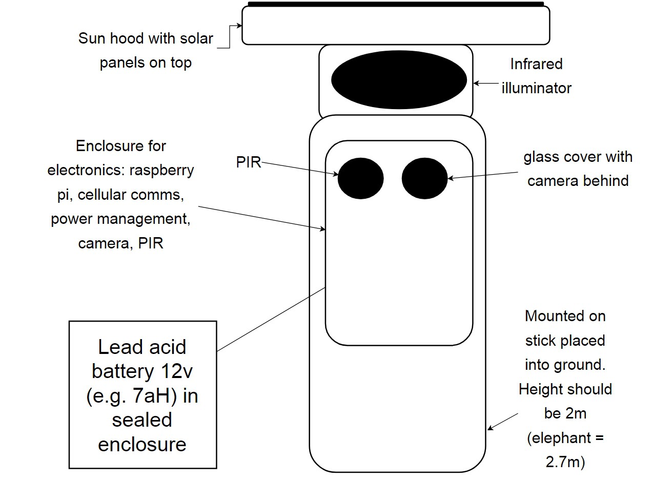
Mounting for the detection devices
09/16/2017 at 19:06 • 0 commentsThis is what I'm working on for mounting the detection devices at present. I'm using a lead acid battery because we will need something that doesn't run out in 12hrs e.g. so 7Ah, and we also will need 12v for the IR illumination anyway. They're not super-expensive - say £15-£20. Although I am a bit worried people might fancy to steal them! Note also, the sun hood with the solar panel on top. To prevent any glare during daytime usage.
![]()
I've come across an opto-coupled circuit that could be a way to isolate the IR illumination (12v) from the raspberry pi. http://www.amphioxus.org/content/raspberry-pi-security-camera
It's difficult to decide which IR illumination to use! We are going to need at least 60m range - maybe right up to 100m. We need to be careful how much power they will need! And also what people can purchase locally! And the cost! I saw a fixed 140 LED light (in enclosure) 12v 18W 850nm supposedly 60m range outdoors (http://www.gowildlifewatching.co.uk/Wildlife%20watching%20IR%20Lights%20Night%20time%20filming%20CCTV%20.htm) but this was £100. Then I've got something like (https://www.amazon.co.uk/Illuminator-Angle-Range-12pcs-Lights/dp/B01MYNZ7TY) promising 100m range with 18W 12v 850nm at only £25. And for a 48 by 32 LED array that would be 180W!
So I think it's a case of building some arrays - getting plans out there for that - and also seeing how we get on with some of these IR illumination products you can buy.
-
elephant-deterrence devices: parts for audio only pi zero version
06/01/2017 at 21:23 • 0 commentsSo to keep costs down I'm trying using the pi zero at the moment.
- Raspberry Pi Zero W with Soldered Header / Male Header - 40 Pin (2 x 20) - Straight [$19.37]
- JustBoom Amp Zero pHAT Maximum output is 30 W (RMS) 55W (Peak) [$33.21]
- SD card
- Adafruit FONA 808 - Mini Cellular GSM + GPS Breakout [£50]
- Slim Sticker-type GSM/Cellular Quad-Band Antenna - 3dBi uFL [£3.50]
- Visaton Cabinet Speaker, 30W nom, 50W max, 8Ω [£21.06x2]
- SIM
- Sealed enclosures for speakers
Details for JustBoom Amp Zero speaker power requirements :
8Ω Speaker
Amp Gain 26dB
Supply Voltage(V) 24
Peak Power(W) 55
Max Power(W) 30
Supply Power(W) 75
So that will be awkward for batteries! And I don't even know if that will be loud enough!
Elephant AI
a system to prevent human-elephant conflict by detecting elephants using machine vision, and warning humans and/or repelling elephants
 Since you won't be using that in end - here are the connections shown to the actual pins on the raspberry pi. We've got the orange wire to pin 2 (5V out) for connecting to VCC on PIR. The brown wire is to pin 6 (Ground) for connecting the GND on the PIR. The yellow wire is to Pin 7 (GPIO4) input from the OUT on PIR. Pin 7 is on the column of pins closest to center of Raspberry Pi. Pins 6 and 2 are on the column closet to edge of Raspberry Pi. Remember if you are using BOARD numbering method you start counting pins from the end of board closest to the microSD card slot.