Keith
Keith-
Compiling PAL equations on Linux
06/09/2026 at 21:36 • 0 commentsI use my logic reader to record the behaviour of programmable logic chips, with the aim of making replacements. So I eventually need to write and compile proposed PAL equations.
I use Linux on my home PC, and don't want to temporarily swap to Windows in the middle of a session.
There are some Linux programs for compiling PALs but I found them limited in devices compared with the Windows programs written by the chip manufacturers.
So I use Linux Wine to run the free Opal suite that runs under MSDOS. Nice and simple, no Windows GUI needed.
Open your Linux terminal and type the following command:
wine cmd
A new prompt will appear inside your terminal that looks like
Microsoft Windows 10.0.19043

Z:\home\keith>
This presents my home directory as a virtual DOS/Windows drive.
I keep my PAL programming work on a USB drive, on a USB expander with the USB dongle for my wireless keyboard and mouse. This is so I can move them all at once to my antique device-programmer and computer. NB I have to do this before switching it on, so Win98 detects them. Win98 will not detect them later on.
Now I have to make my USB drive look like a DOS drive to wine. The command winecfg will open a GUI. I have previously defined my MSDOS-formatted USB drive (named USBDOS, appearing as /media/keith/USBDOS) to be drive G: so I simply type G: and I am 'in' that drive.
I then type
cd DOS/opal/Applix_1616/logic
and I'm in a workspace.
I have had some issues with wine before, so I installed a program called DosBox.
Now any attempt to run a DOS program from Wine opens a DosBox window, briefly, then closes.
So I now open DosBox from my Linux Games options, and again a Z drive is shown.
Type:
mount [virtual-drive-letter] [path-to-linux-folder]which in my case is
mount d /media/keith/USBDOS/DOS
DosBox is annoyingly accurate in that it won't handle file/directory names longer than 8 characters. I can cd to OPAL but not to Applix_1616. It suggests I use Applix~1, and this works. I then cd to the logic directory.
From there I can run
..\..\eqn2jed.exe -d PAL16R8 1616_U5.EQN
-
Pinouts and connections
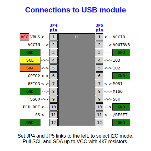
11/17/2025 at 20:19 • 0 commentsThe USB module just has power, ground and the two I2C signals connecting.
![]()
I used just one MCP23017 chip, with GPB7 connected to D0, D1, D2 and D3 in turn. This needs that pin direction set to input instead of output. For a more general purpose device, use two of these chip and set their slave addresses to be different (using pins 15, 16 17).
![]()
Here are the connections to simple programmable logic chips with all their possible output pins (pale blue cells) set to outputs. Some cells are always inputs (green cells).
In practice, some of the possible output cells may be inputs. You may not know their signal directions at first, so current-limiting resistors to those lines are a wise precaution to prevent damage.
![]()
The pin ordering on the right may seem a bit irregular, but it allows the addresses to be cycled from 0 to 2^n where n is the number of address pins minus 1.
You can also use the two-chip version to read EPROM chips. The /CS and /OE pins can be tied down for reading. Where pins become VPP or /PGM, simply hold A11, A14, and A15 high as required. Pin 28 can be permanently connected to VCC, but pin 26 will need switching to VCC, or buffered to be able to supply enough current to drive a 24-pin EPROM.
![]()