 Keith
KeithSimplicity is the key feature here. You don't need to make or buy a PCB, build it, or do much wiring.
Components:
- USB to I2C module
- I2C to 16-bit parallel I/O module or chip
- Two 4k7 resistors to pull up the I2C bus signals
Optional parts:
- Current limiting resistors where you might connect two outputs
- LED bar to show output pin activity
- Switch for VCC to logic chip power
Operation
I had to write some C code, because the demo code from FTDI had the USB-to-I2C module driving a serial EEPROM. The I2C-to-PIO chip is significantly different. I wasted many hours trying to adapt the demo code before asking an AI bot what was wrong with my code. It quickly spotted what I had done, and gave me some working code. This was the most time-consuming task, which won't need to be done again.
I quickly wrote a short routine to test the I/O by driving an LED bar.
I then wired the port A to the PAL14L4 pins 1 to 8. Port B had the less-significant bits wired to the other PAL input pins and the most significant bits to the four outputs. With 14 inputs and 4 outputs, a single 16-bit IO module can only read 2 outputs at a time. I decided to read just one output at a time, because it was quicker to run the reader program four times (4 x 40 seconds) than to write more code.
My code read the outputs to an ASCII text file, for both the original PAL14L4 and my self-made GAL16V8. Comparing the files using the Linux diff command quickly identified which outputs were identical, and where they were not.
Then it was a matter of tweaking my logic expressions until the matched. Fortunately I had equations from a similar chip for another machine, which proved a good starting point. With a bit of intuition and several iterations, I successfully duplicated the original logic.
I have a device that should have been able to read the fuse maps directly, but for some reason it was not working for 2 of the four outputs. Hence I had to create this project to figure those out the hard way.
Advantages
- Off the shelf modules
- Simple and quick to assemble
- Input pins can be individually changed
- Software in C
- Runs on a desktop PC
- Easily expandable for more I/O pins
- Cheap enough to make and send to people who don't want to send their chips to me
Disadvantages
- About 100 time slower than a device reader, but still only about 10s to cycle through the 16384 possible input combinations. This is trivial compared to all the other time spent.
Of the 600 microseconds per address, most of this is due to USB overheads. USB is great for transferring large packets of data, but less efficient for a few bytes at a time.
Cost
UMFT4222EV module about £15
MCP23017 module (or chip) a few pounds
Comparison with other methods
Reading by using a ROM socket adaptor
This is simple but does need a ROM reading device.
https://dreamjam.co.uk/emuviews/readpal.php
Tony Brewer's PAL14L4 Reader
This uses counters to drive the input pins and is specific to the Memotech
Needs building on prototyping board
The software is written in Z80 assembler.
http://www.primrosebank.net/computers/mtx/projects/pal_reader/palreader_build.htm
A QBASIC program for reading PAL outputs and automatically deducing the logic equations is mentioned, but I can't find it for downloading.
Ideas for future work
- Expand design to cope with 24-pin PAL chips
- Sense when pins are input, output, or disabled
- Find how to automate equation recovery with Espresso or Logic Friday
- Remove the USB time overhead by talking directly to the I/O chip from the I2C bus of a Raspberry Pi
There is hobbyist demand for reverse engineering programmable logic from old machines to preserve them. The combinatorial chips are simple, but registered chips are usually harder. For example, the PAL chips in the Applix 1616 machine had their security bits blown and the original inventor has lost/forgotten the original equations. People have discussed trying 'brute force' analysis by bombarding...
Read more »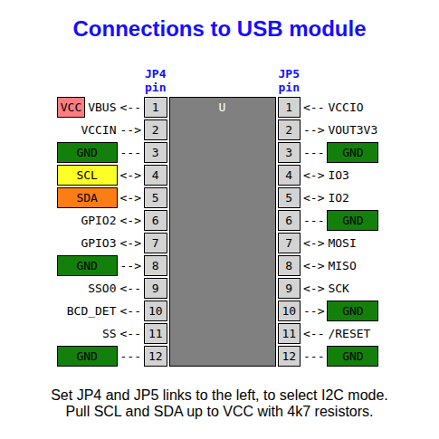


 Alex Brown
 mit41301
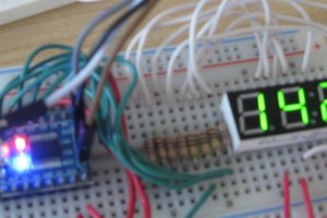
 Andrew Clapp
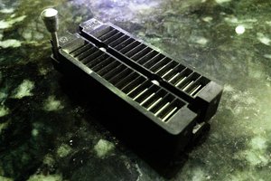
 SHAOS
SHAOS