 Arnov Sharma
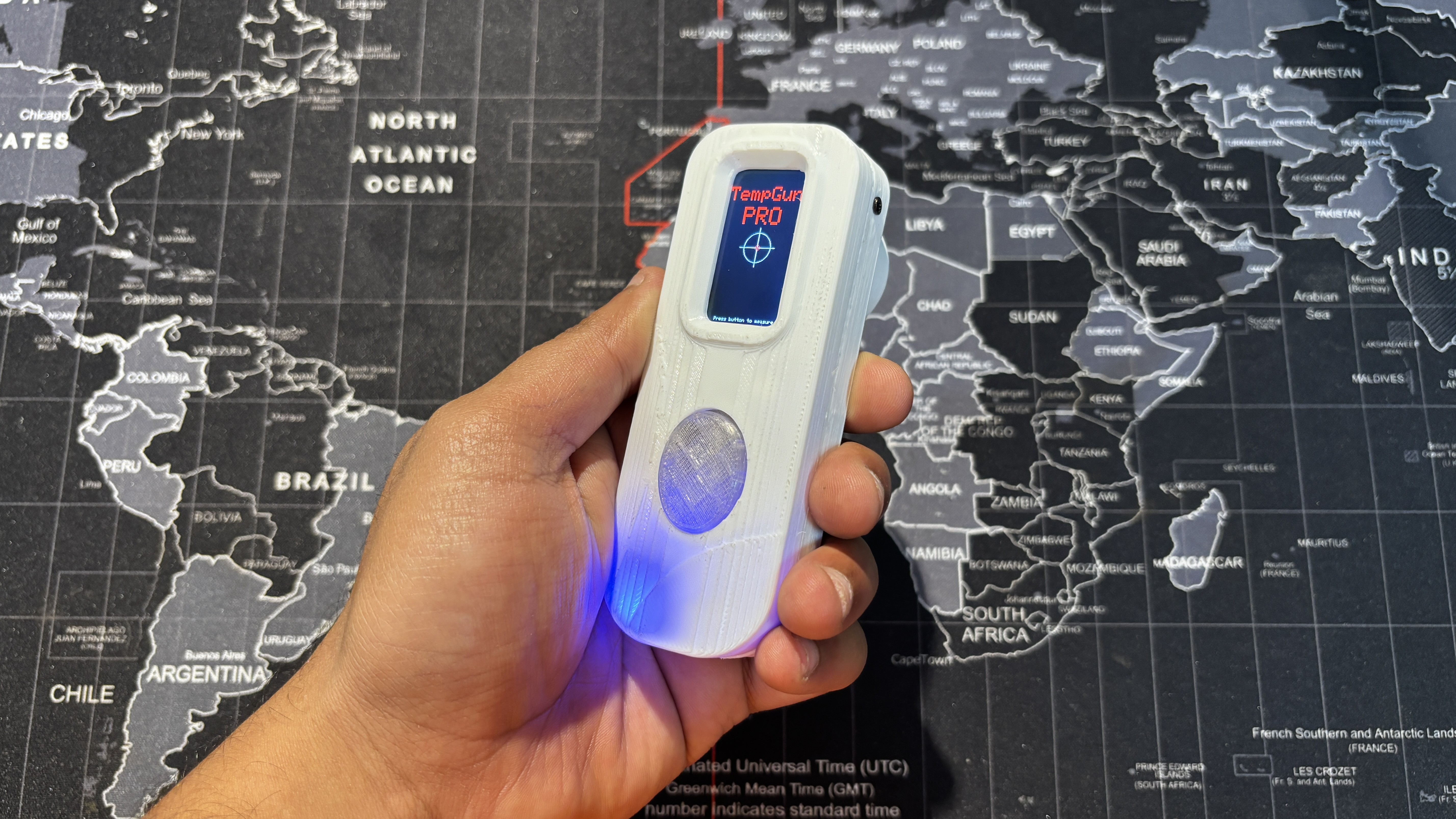
The aim behind this project was straightforward. I needed a temperature meter to measure different things while working with electronics and 3D printing. I already had a Fluke temperature gun, but when it stopped working, I needed an urgent alternative, something cheaper that could still perform almost as well.
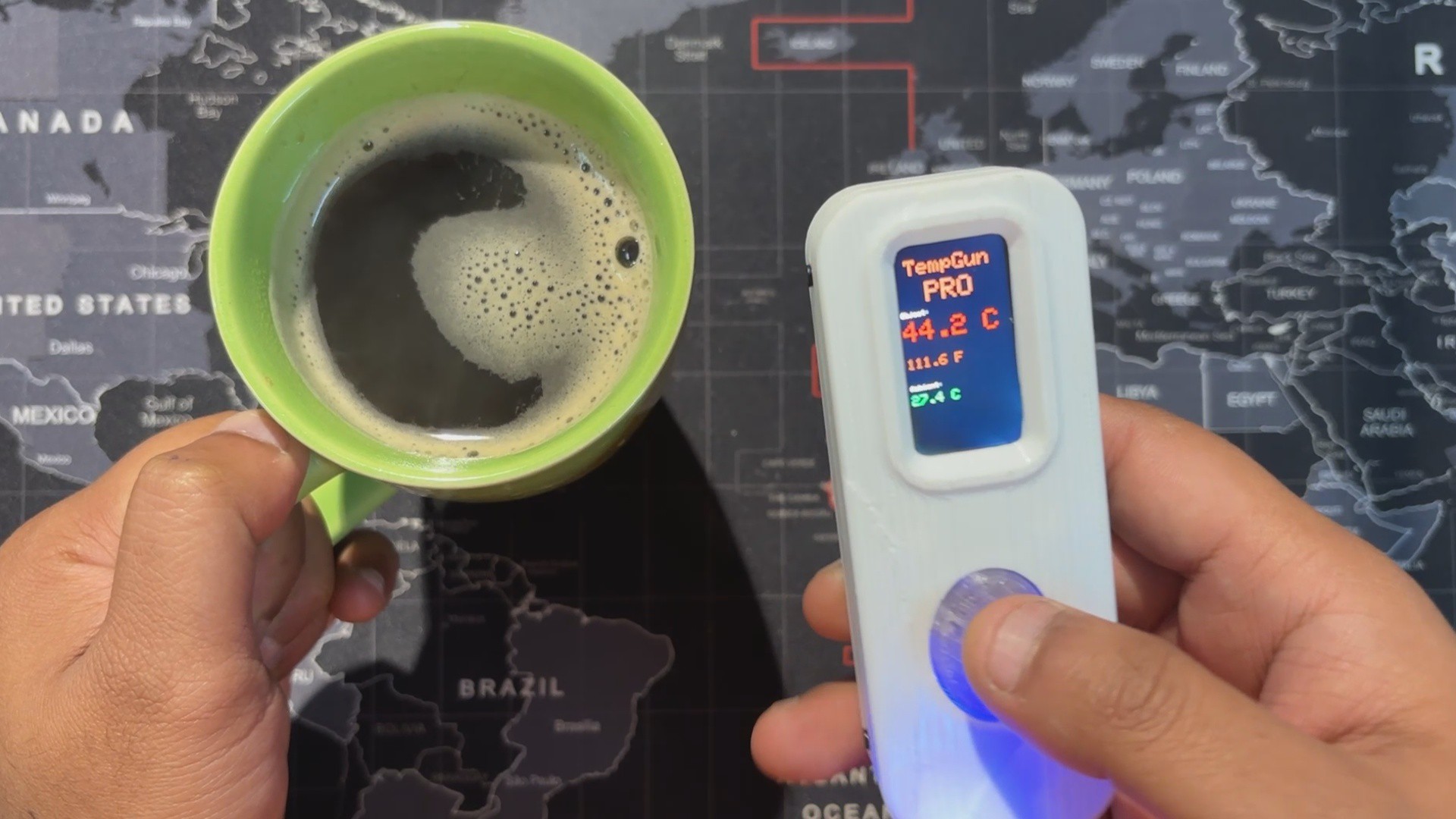
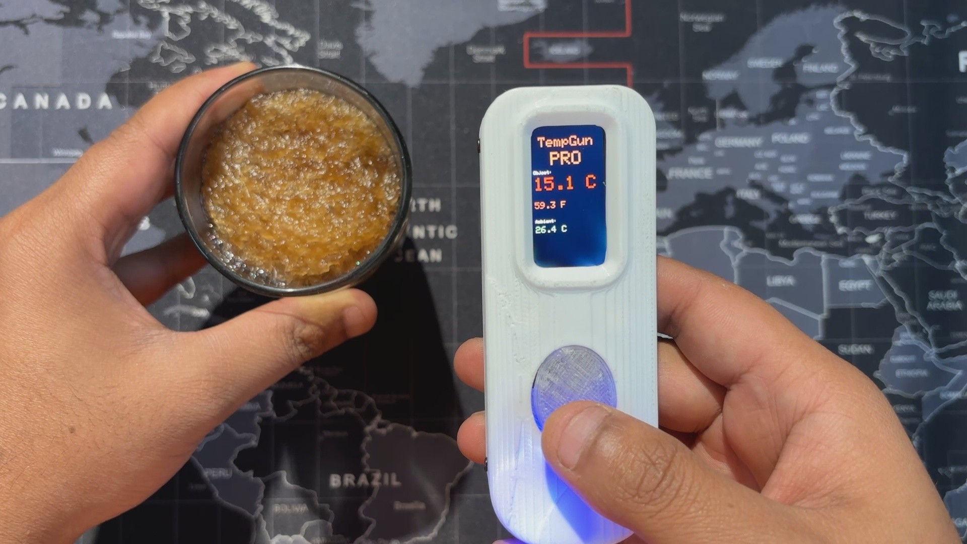
The best part was how easy it was to build. I reused my earlier Medic Mini project, an ESP32‑C6 dev board with a screen, buttons, and battery circuit. I just added an MLX90614 infrared temperature sensor to the GPIO pins, wrote up a quick code, made an enclosure, and the project was ready.
This article walks you through the process in a few easy steps.
Medic Mini Mainboard
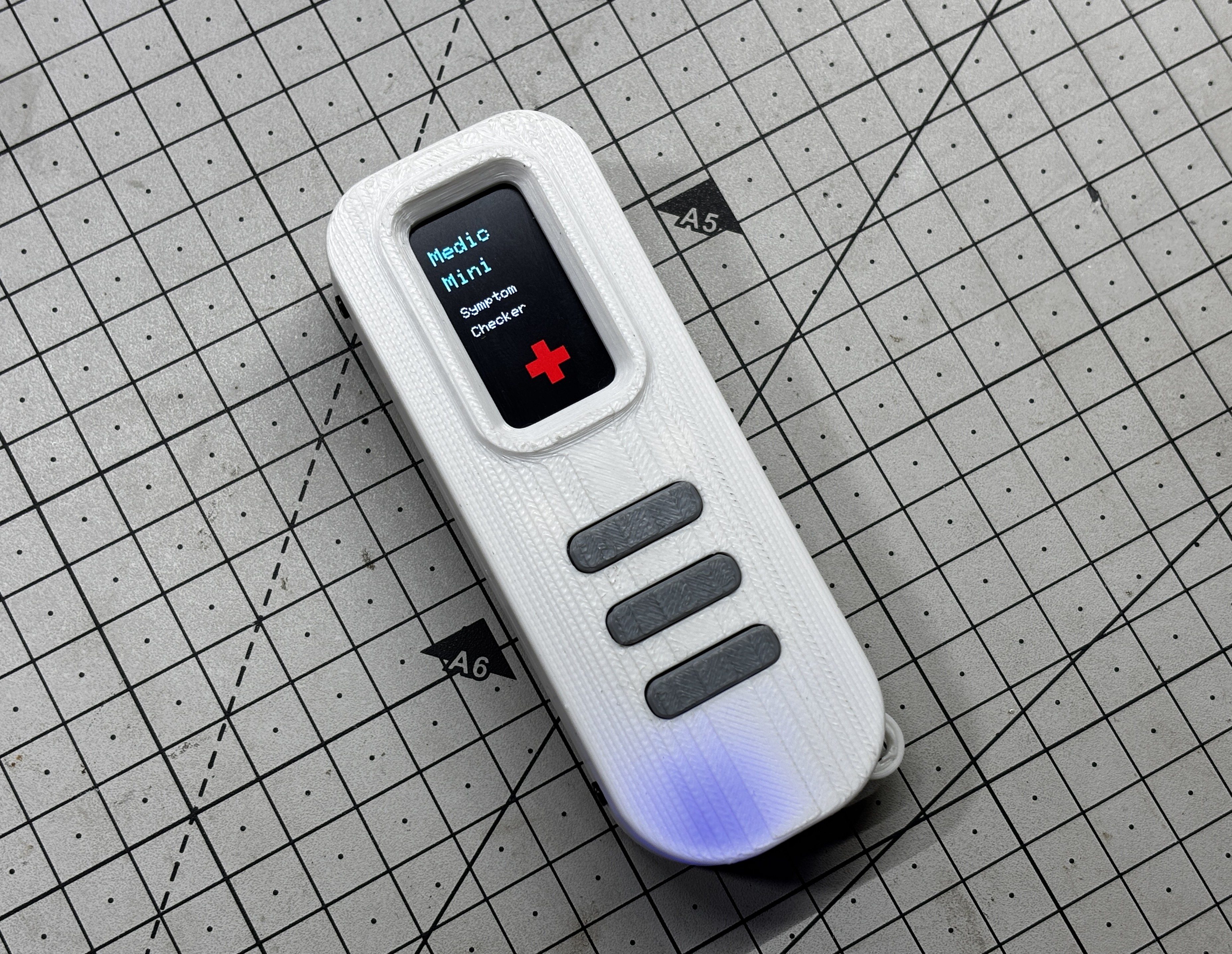
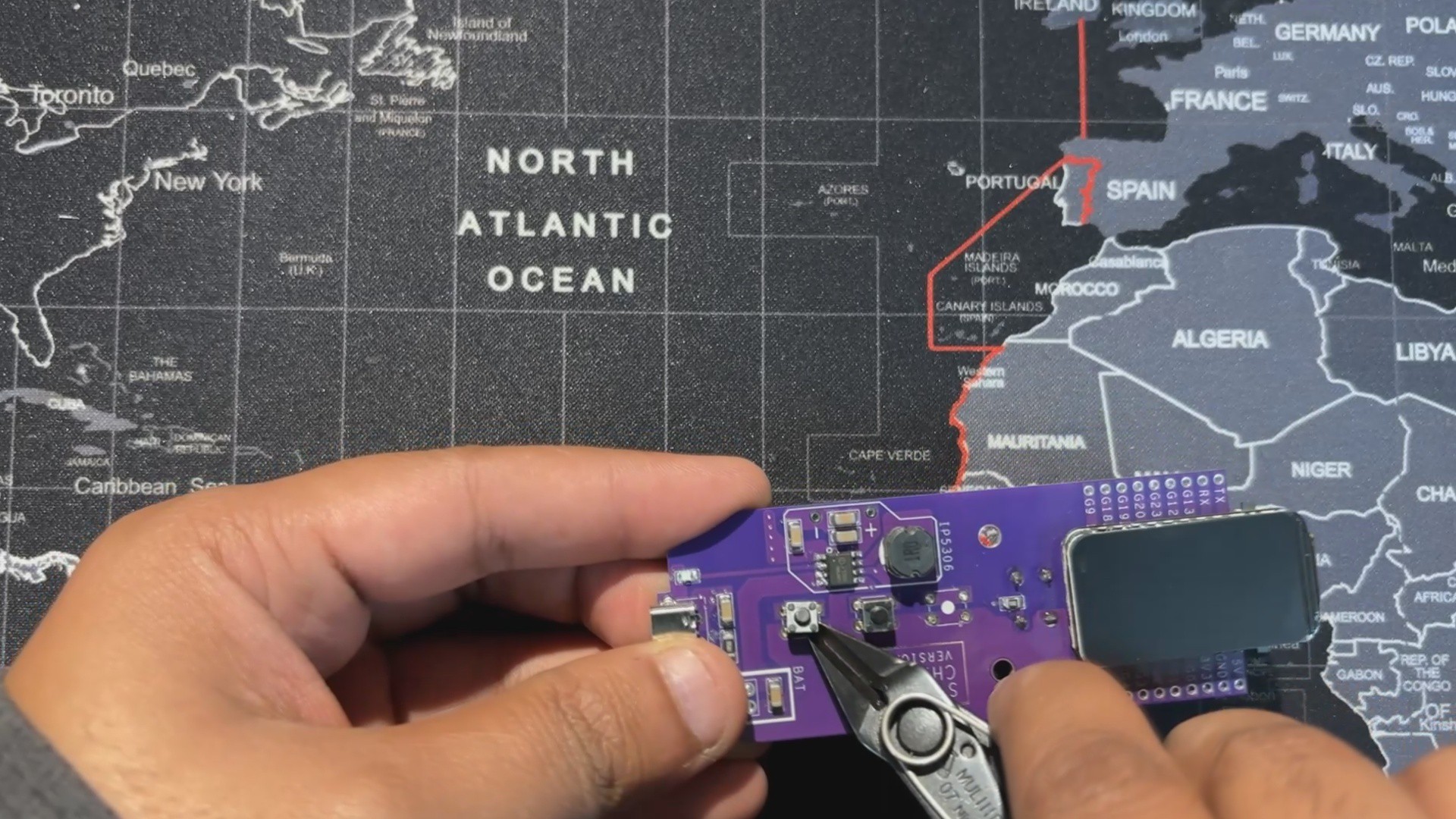
We built TempGun Pro by reusing the Medic Mini main board with just a few small modifications and add‑ons. To recap, Medic Mini was a handheld self‑diagnostic tool powered by an ESP32‑C6 and a 1.47" Waveshare display, all packed into a custom PCB and 3D‑printed enclosure. It featured three tactile buttons to guide users through symptom checks and offered quick suggestions without needing apps or internet.
The interface was straightforward: one symptom at a time, answered with Yes, No, or Not Sure. Based on those inputs, the device provided a basic diagnostic suggestion, making health checks fast and accessible.
I designed Medic Mini as a compact, standalone tool that is easy to use and built entirely from scratch, combining hardware, logic, and design into one project.
You can check out more about Medic Mini from its article page.
https://www.hackster.io/Arnov_Sharma_makes/medic-mini-f0895d#toc-materials-required-0
MLX90614

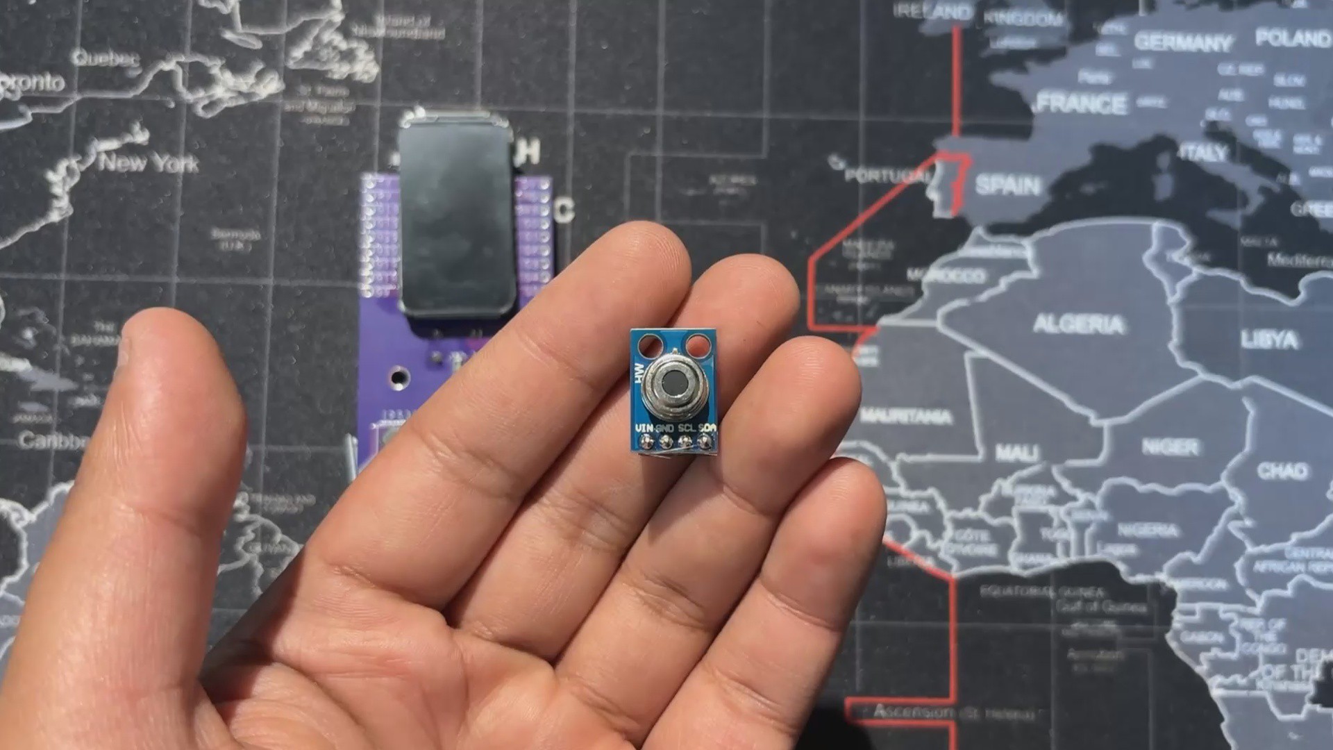
The MLX90614 is a digital infrared thermometer sensor developed by Melexis. Unlike traditional sensors that require physical contact, it detects infrared radiation emitted by objects and converts it into temperature readings. This makes it ideal for applications like handheld thermometers, industrial monitoring, and even medical devices.
It's a 3.3V device and uses I2C for communication.
The MLX90614 uses the principle of black‑body radiation. Every object emits infrared energy proportional to its temperature. The sensor’s thermopile detector captures this radiation, and an internal signal processor converts it into a digital temperature value.
You can check out the MLX90614 from below link
PCB Design
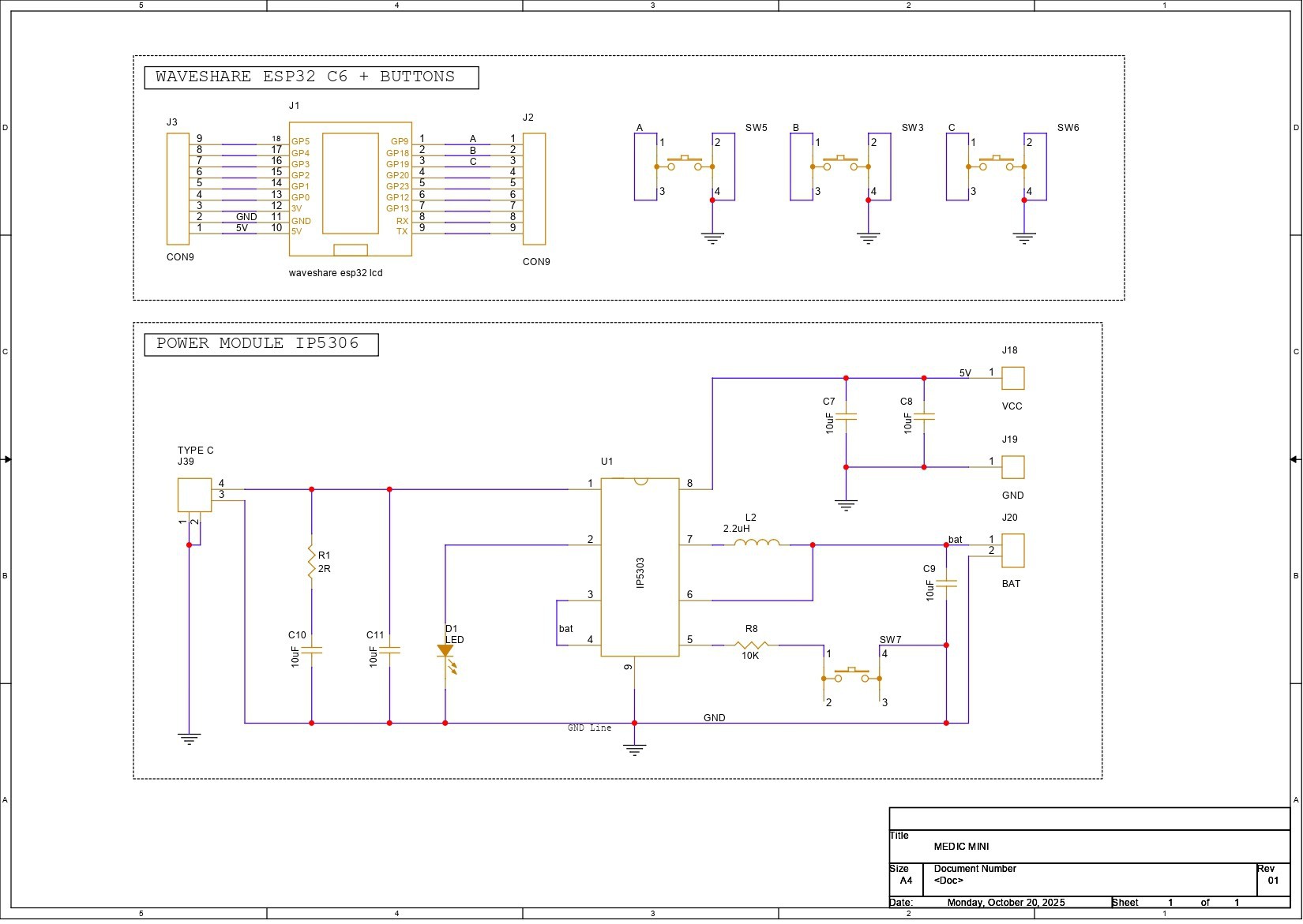


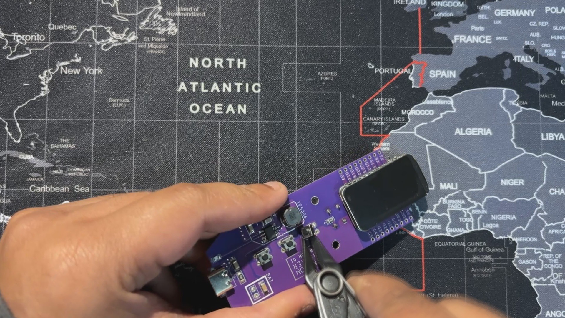
This is a schematic of the Medic Mini PCB design, which is split into two main sections. First, we built the schematic around the Waveshare ESP32-C6 Dev Board, which connects to three tactile buttons for user input. These buttons are wired to GPIO9, GPIO18, and GPIO19, with each switch also tied to GND. When a button is pressed, the corresponding GPIO pin is pulled low, registering a valid input. We will be later using GPIO18 as a temperature reading button! and will be using GPIO4 and GPIO5 as I2C pins.
The second section handles power delivery. We use the IP5306 power management IC, which boosts the 3.7V from a lithium-ion cell to a stable 5V at 2A, enough to reliably power the ESP32 board and display. The module also includes a charging status LED; it blinks while charging and stays solid once the battery is full. Built-in features like overcharge protection, low battery cutoff, and full charge cutoff help extend battery life and prevent damage from unsafe voltage levels.
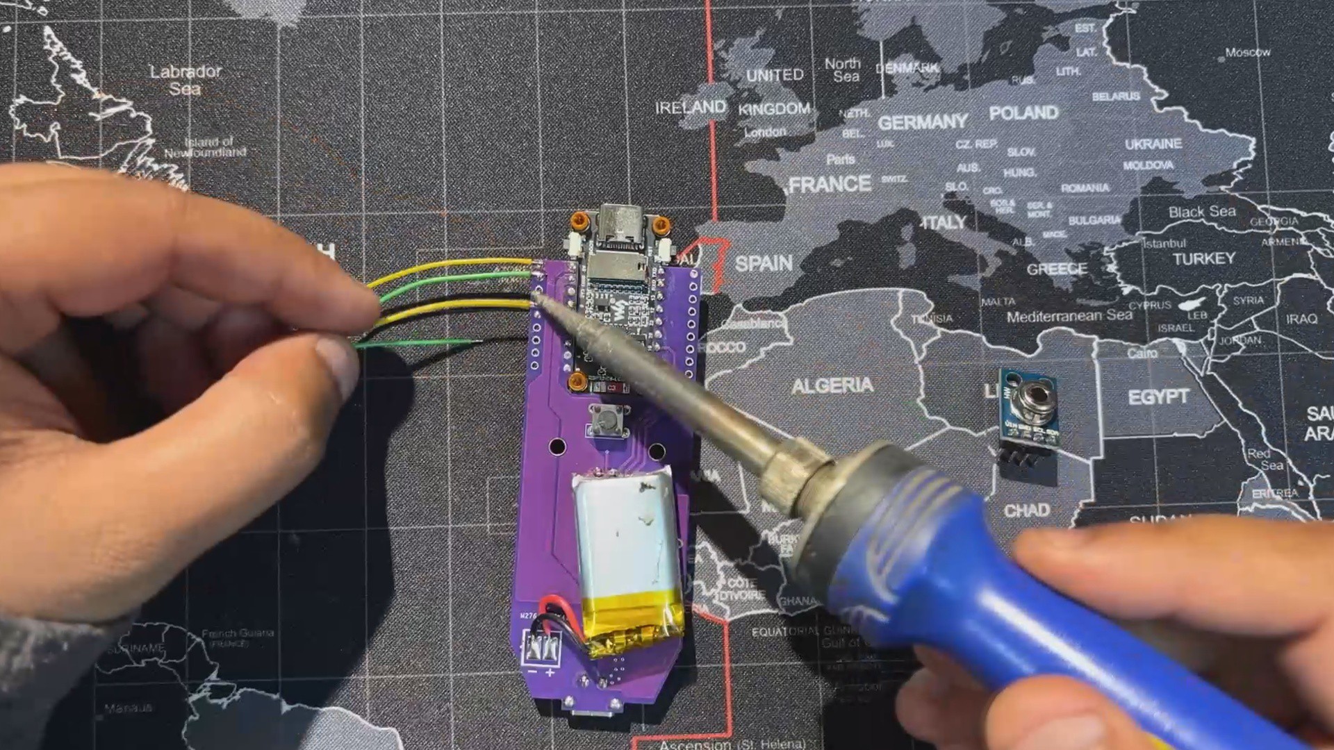
Using the dimensions from the CAD model, we prepared the PCB outline and then placed the buttons in their mounting positions as specified in the design. We did the same for the Waveshare ESP32 board, the Type-C port, and the mounting holes. The rest of the components were placed wherever we found adequate space, and then we connected the tracks and finalized the board.
After completing the PCB design, we exported the Gerber data and shared it with a PCB manufacturer to get samples made.
PCBWAY
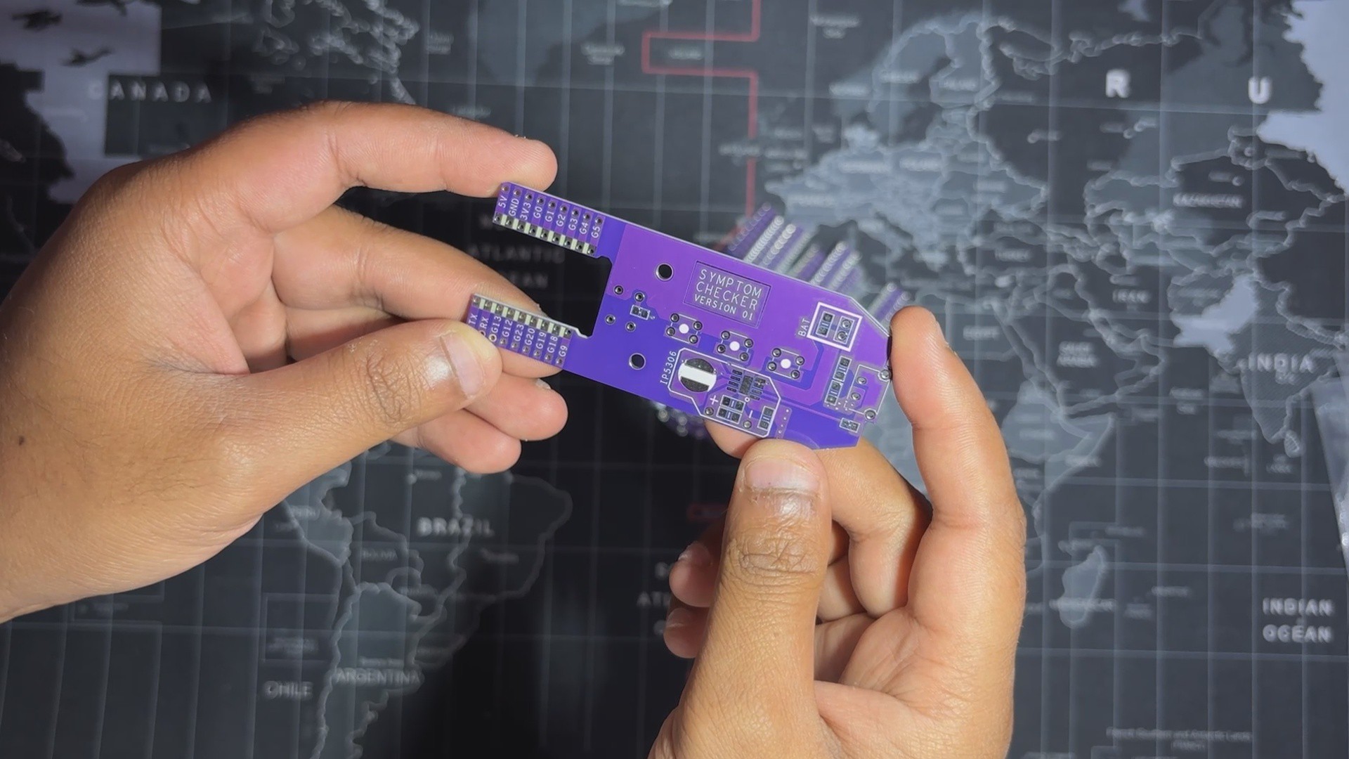
Once the board design was finalized, I opted for a purple solder mask with white silkscreen...
Read more »

 sjm4306

 Vedant Paranjape
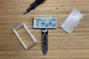
 Jon
Jon