 Arnov Sharma
-
1Medic Mini PCB Edit
![]()
![]()
![]()
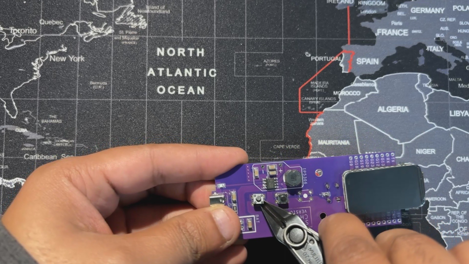
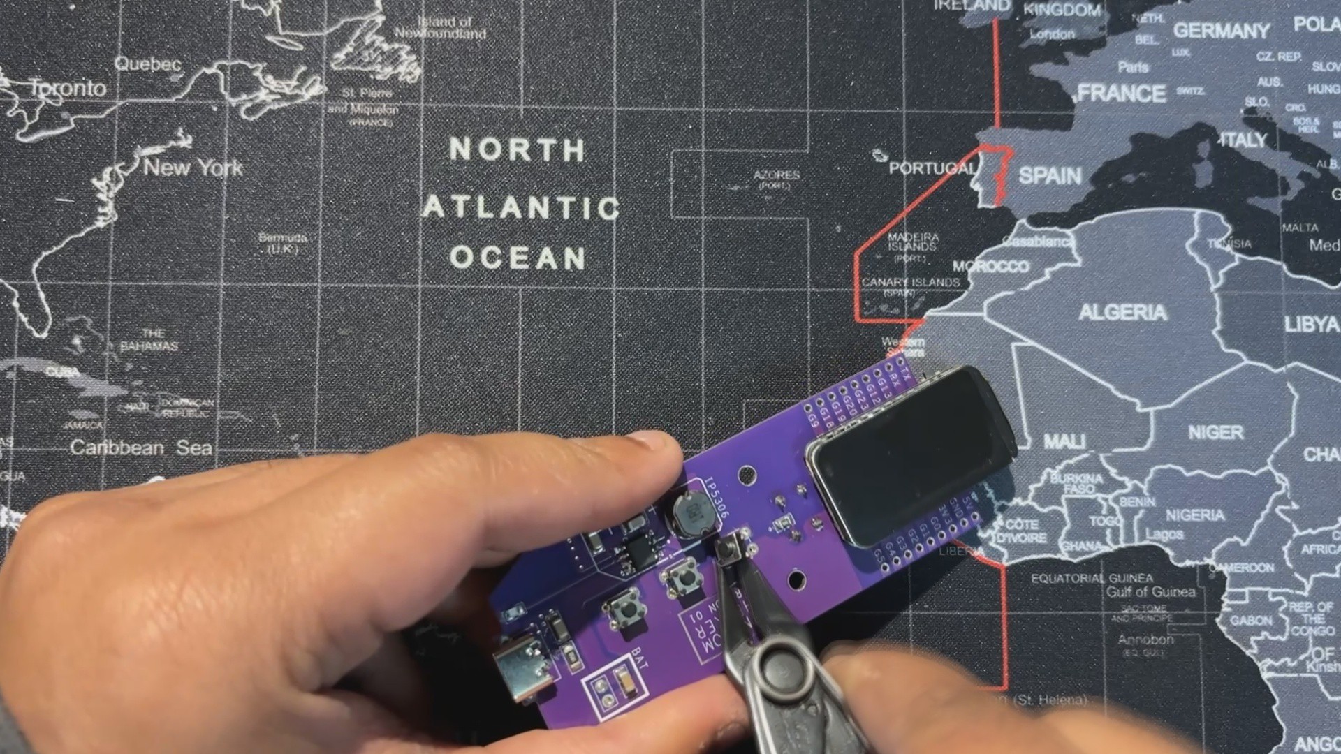
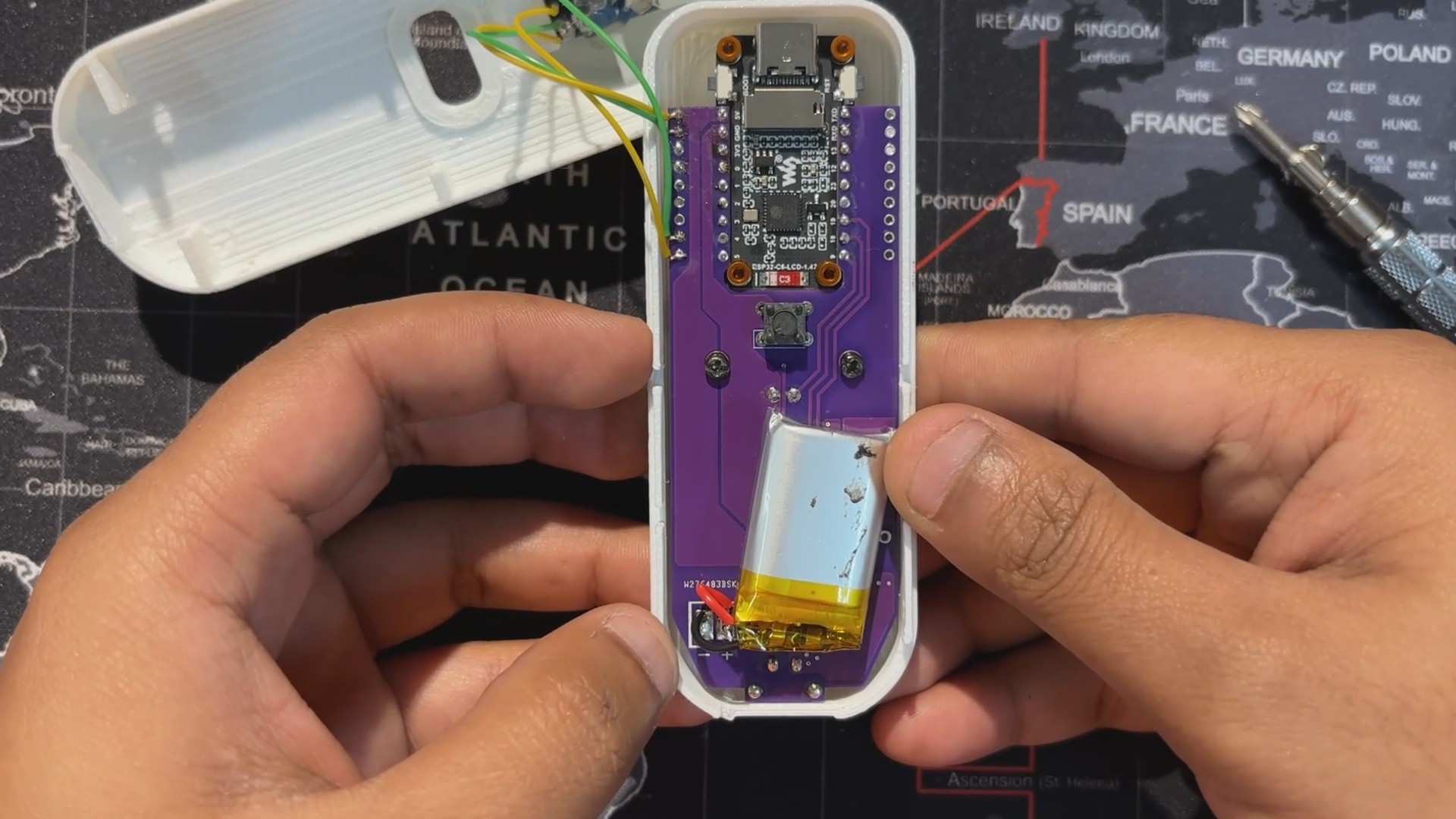
For this build, we reused the Medic Mini circuit but modified the button layout.
- The tactile push buttons connected to GPIO9 and GPIO19 were removed, since they weren’t needed.
- The center button, wired to GPIO18, was kept and repurposed as the temperature trigger button.
-
2TEMPERATURE SENSOR WIRING
![]()
![]()
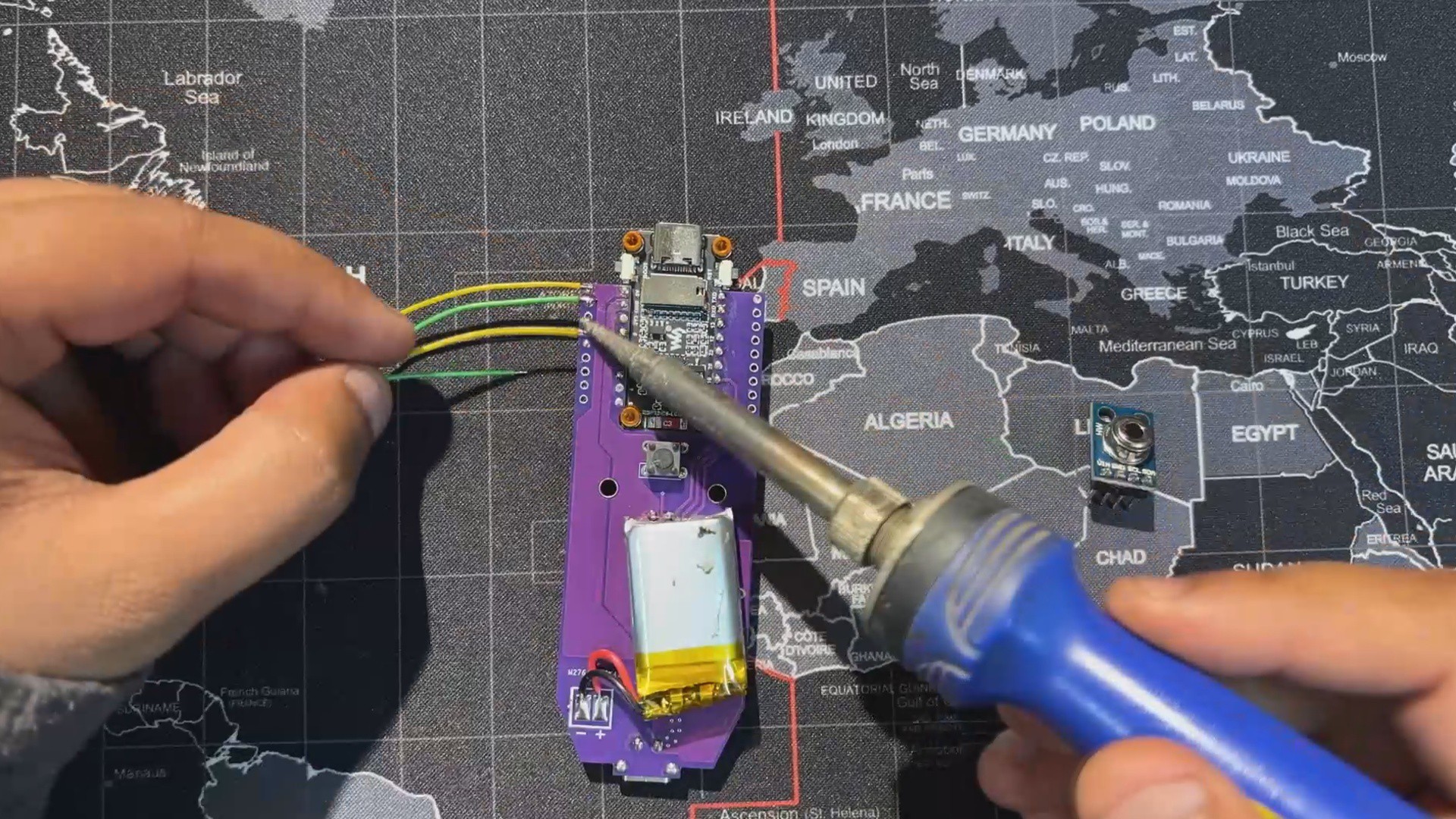
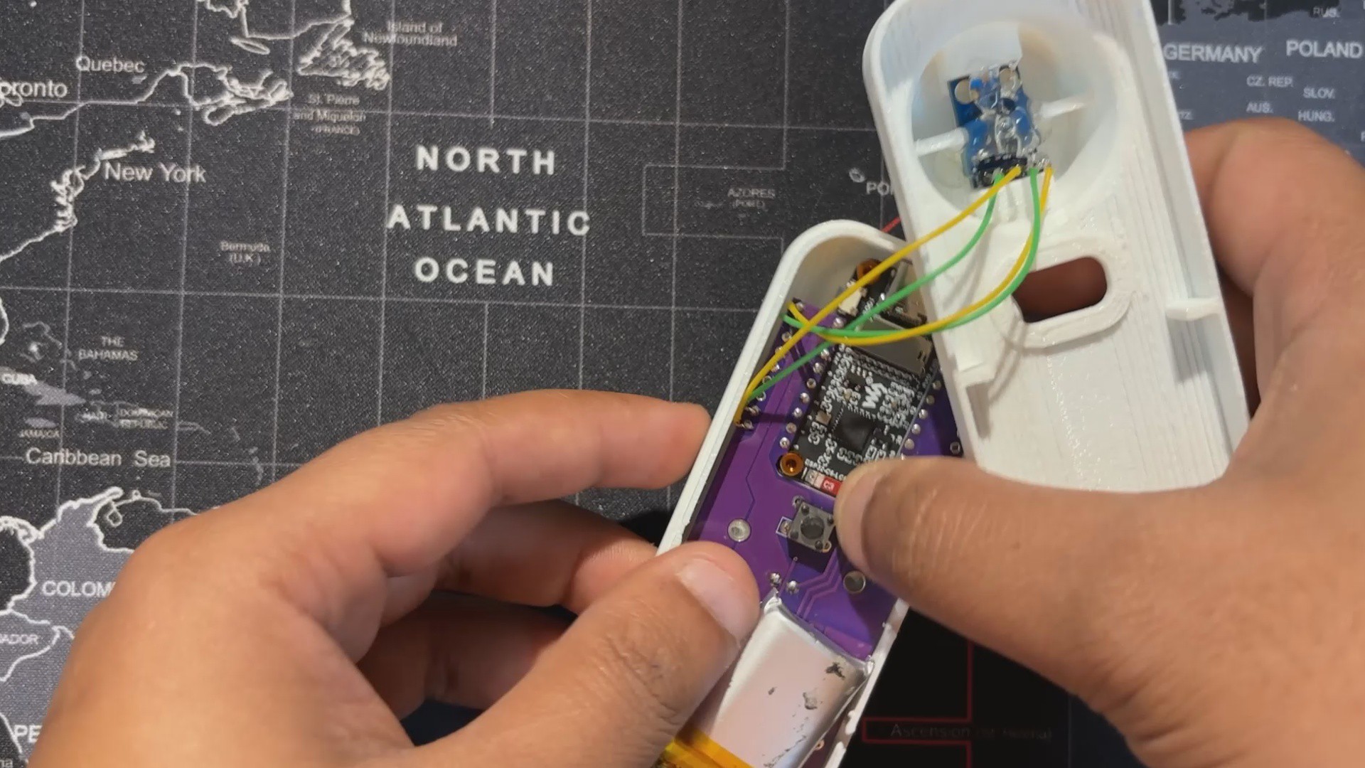
For wiring, we use four connecting wires.
- GPIO4 and GPIO5 of the ESP32‑C6 (SDA and SCL) are linked to the I2C pins of the MLX90614 sensor.
- VCC is connected to the 3.3V pin, and GND goes to ground.
This completes the basic four‑wire setup needed to power the sensor and enable communication with the Medic Mini board.
-
3CODE
This is the code we prepared for our TempGun Pro, and it's a simple one; let me explain.
#include <Arduino_GFX_Library.h> #include <Wire.h> #include <Adafruit_MLX90614.h> // --- Pin Definitions for WAVESHARE ESP32-C6 LCD BOARD --- #define LCD_MOSI 6 #define LCD_SCLK 7 #define LCD_CS 14 #define LCD_DC 15 #define LCD_RST 21 #define LCD_BL 22 // I2C pins for MLX90614 (as you confirmed they work) #define SDA_PIN 4 #define SCL_PIN 5 // Button pin #define TRIGGER_PIN 18 // --- Global Objects --- // Create an MLX90614 object Adafruit_MLX90614 mlx = Adafruit_MLX90614(); // Create the display objects Arduino_DataBus *bus = new Arduino_ESP32SPI( LCD_DC, LCD_CS, LCD_SCLK, LCD_MOSI, GFX_NOT_DEFINED ); Arduino_GFX *gfx = new Arduino_ST7789( bus, LCD_RST, 2, true, 172, 320, 34, 0, 34, 0 ); // --- State and Timing Variables --- enum GunState { READY, MEASURING, DISPLAY_RESULT }; GunState currentState = READY; unsigned long lastMeasurementTime = 0; const unsigned long resultDisplayTime = 5000; // Display result for 5 seconds // Button debouncing bool lastButtonState = HIGH; unsigned long lastDebounceTime = 0; const unsigned long debounceDelay = 50; // --- Drawing Functions --- void drawReadyScreen() { gfx->fillScreen(BLACK); // Draw the crosshair int centerX = gfx->width() / 2; // Center of 320px width int centerY = gfx->height() / 2; // Center of 172px height gfx->drawCircle(centerX, centerY, 30, WHITE); gfx->drawFastHLine(centerX - 40, centerY, 80, WHITE); gfx->drawFastVLine(centerX, centerY - 40, 80, WHITE); gfx->drawCircle(centerX, centerY, 5, RED); gfx->fillCircle(centerX, centerY, 2, RED); // --- Draw "TempGun Pro" title --- int16_t x1, y1; uint16_t w, h; // Draw "TempGun" gfx->setTextSize(4); gfx->setTextColor(RED); gfx->getTextBounds("TempGun", 0, 0, &x1, &y1, &w, &h); int tempgun_y = 35; gfx->setCursor((gfx->width() - w) / 2, tempgun_y); gfx->print("TempGun"); // Draw "PRO" below it, slightly bigger gfx->setTextSize(5); // Slightly bigger gfx->getTextBounds("PRO", 0, 0, &x1, &y1, &w, &h); int pro_y = tempgun_y + h + 2; // Position below "TempGun" gfx->setCursor((gfx->width() - w) / 2, pro_y); gfx->println("PRO"); // --- Draw instruction text --- gfx->setTextSize(1); gfx->setTextColor(WHITE); gfx->getTextBounds("Press button to measure", 0, 0, &x1, &y1, &w, &h); gfx->setCursor((gfx->width() - w) / 2, gfx->height() - 15); gfx->println("Press button to measure"); } void drawMeasuringScreen() { // Redraw crosshair in red to indicate scanning int centerX = gfx->width() / 2; int centerY = gfx->height() / 2; gfx->drawCircle(centerX, centerY, 30, RED); gfx->drawFastHLine(centerX - 40, centerY, 80, RED); gfx->drawFastVLine(centerX, centerY - 40, 80, RED); // Clear the old text and write new text int16_t x1, y1; uint16_t w, h; gfx->setTextSize(1); gfx->setTextColor(ORANGE); gfx->getTextBounds("SCANNING...", 0, 0, &x1, &y1, &w, &h); gfx->fillRect(0, gfx->height() - 15, gfx->width(), h + 5, BLACK); gfx->setCursor((gfx->width() - w) / 2, gfx->height() - 15); gfx->println("SCANNING..."); } void drawResultScreen(float objTemp, float ambTemp) { gfx->fillScreen(BLACK); // --- Draw "TempGun Pro" title --- int16_t x1, y1; uint16_t w, h; // Draw "TempGun" gfx->setTextSize(3); gfx->setTextColor(ORANGE); gfx->getTextBounds("TempGun", 0, 0, &x1, &y1, &w, &h); int tempgun_y = 25; gfx->setCursor((gfx->width() - w) / 2, tempgun_y); gfx->print("TempGun"); // Draw "PRO" below it, slightly bigger gfx->setTextSize(4); // Slightly bigger gfx->getTextBounds("PRO", 0, 0, &x1, &y1, &w, &h); int pro_y = tempgun_y + h + 2; // Position below "TempGun" gfx->setCursor((gfx->width() - w) / 2, pro_y); gfx->println("PRO"); // --- Adjusted Temperature Values Layout --- int label_y = 100; // Shifted down from 80 int value_y_c = label_y + 15; // Position for Celsius value int value_y_f = value_y_c + 55; // Position for Fahrenheit value int ambient_label_y = value_y_f + 40; // Position for Ambient label int ambient_value_y = ambient_label_y + 15; // Position for Ambient value // Object Temperature gfx->setTextSize(1); gfx->setTextColor(WHITE); gfx->setCursor(10, label_y); gfx->println("Object:"); gfx->setTextSize(4); gfx->setTextColor(RED); gfx->setCursor(10, value_y_c); gfx->print(objTemp, 1); gfx->println(" C"); // Fahrenheit conversion gfx->setTextSize(2); gfx->setTextColor(ORANGE); gfx->setCursor(10, value_y_f); gfx->print((objTemp * 9.0 / 5.0) + 32.0, 1); gfx->println(" F"); // Ambient Temperature gfx->setTextSize(1); gfx->setTextColor(WHITE); gfx->setCursor(10, ambient_label_y); gfx->println("Ambient:"); gfx->setTextSize(2); gfx->setTextColor(GREEN); gfx->setCursor(10, ambient_value_y); gfx->print(ambTemp, 1); gfx->println(" C"); } void drawSensorErrorScreen() { gfx->fillScreen(BLACK); gfx->setCursor(10, 80); gfx->setTextSize(2); gfx->setTextColor(RED); gfx->println("Sensor Error!"); gfx->setCursor(10, 110); gfx->println("Check wiring &"); gfx->setCursor(10, 140); gfx->println("I2C address."); } // --- Main Arduino Functions --- void setup() { Serial.begin(115200); delay(1000); Serial.println("SETUP: Starting..."); Wire.begin(SDA_PIN, SCL_PIN); Serial.println("SETUP: Finding MLX90614 sensor..."); if (!mlx.begin()) { Serial.println("SETUP: ERROR - Failed to find MLX90614 sensor."); pinMode(LCD_BL, OUTPUT); digitalWrite(LCD_BL, HIGH); gfx->begin(); drawSensorErrorScreen(); while (1); } Serial.println("SETUP: MLX90614 sensor found."); Serial.println("SETUP: Initializing Display..."); pinMode(LCD_BL, OUTPUT); digitalWrite(LCD_BL, HIGH); gfx->begin(); Serial.println("SETUP: Display initialized."); pinMode(TRIGGER_PIN, INPUT_PULLUP); Serial.println("SETUP: Button initialized."); Serial.println("SETUP: Drawing ready screen."); drawReadyScreen(); Serial.println("SETUP: Complete. Starting loop."); } void loop() { static unsigned long lastHeartbeat = 0; if (millis() - lastHeartbeat > 5000) { Serial.println("LOOP: Heartbeat - loop is running."); lastHeartbeat = millis(); } int reading = digitalRead(TRIGGER_PIN); if (reading != lastButtonState) { lastDebounceTime = millis(); } if ((millis() - lastDebounceTime) > debounceDelay) { if (reading == LOW && currentState == READY) { Serial.println("LOOP: Button pressed. Starting measurement."); currentState = MEASURING; lastMeasurementTime = millis(); drawMeasuringScreen(); } } lastButtonState = reading; switch (currentState) { case READY: break; case MEASURING: if (millis() - lastMeasurementTime > 500) { Serial.println("LOOP: Taking temperature reading..."); float objectTemp = mlx.readObjectTempC(); float ambientTemp = mlx.readAmbientTempC(); Serial.print("LOOP: Object Temp: "); Serial.print(objectTemp); Serial.println(" C"); Serial.print("LOOP: Ambient Temp: "); Serial.print(ambientTemp); Serial.println(" C"); drawResultScreen(objectTemp, ambientTemp); currentState = DISPLAY_RESULT; lastMeasurementTime = millis(); } break; case DISPLAY_RESULT: if (millis() - lastMeasurementTime > resultDisplayTime) { Serial.println("LOOP: Result display timeout. Returning to ready."); currentState = READY; drawReadyScreen(); } break; } } -
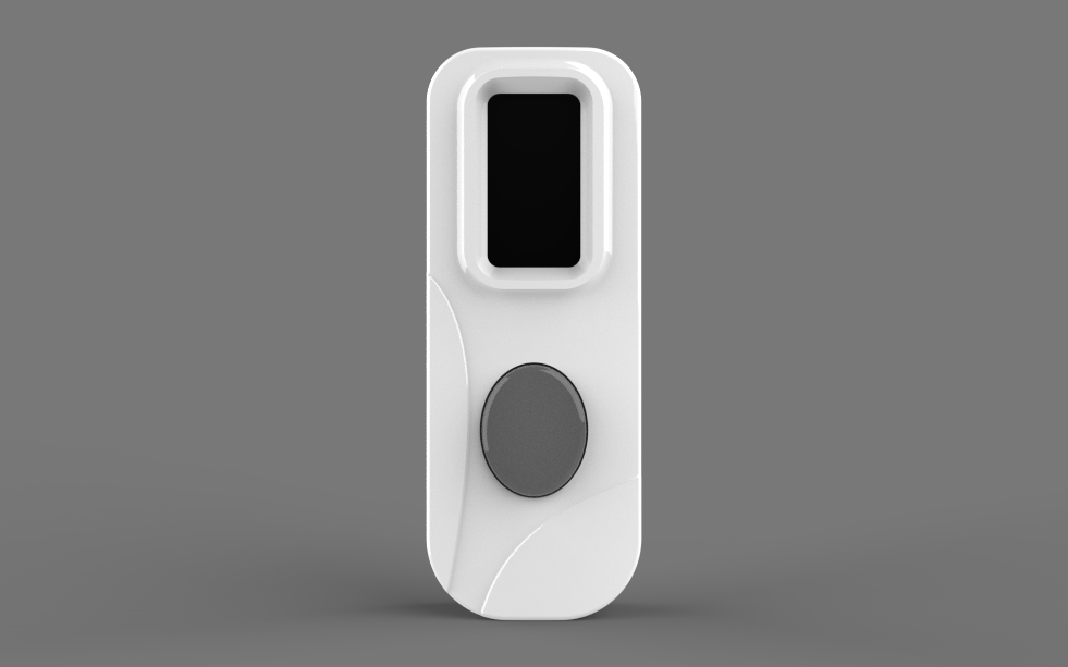
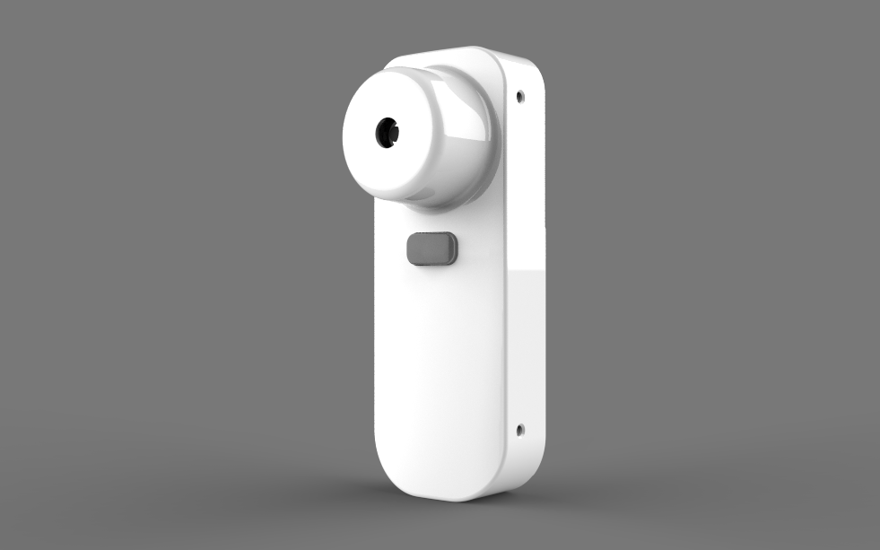
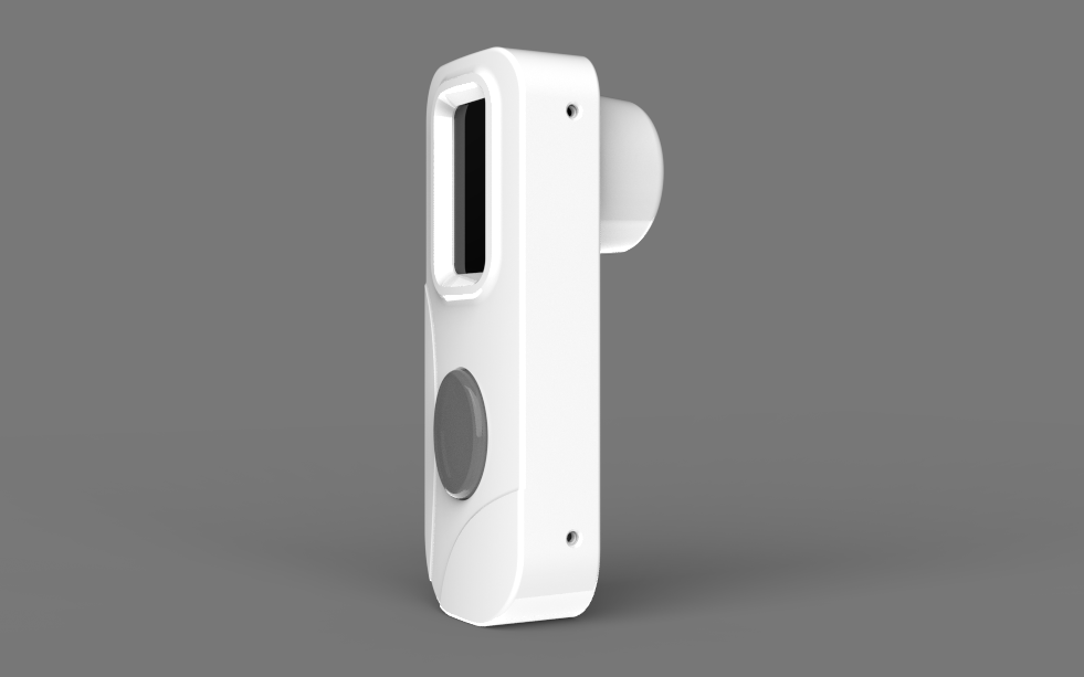
4Enclosure Design
![]()
![]()
![]()
![]()
![]()
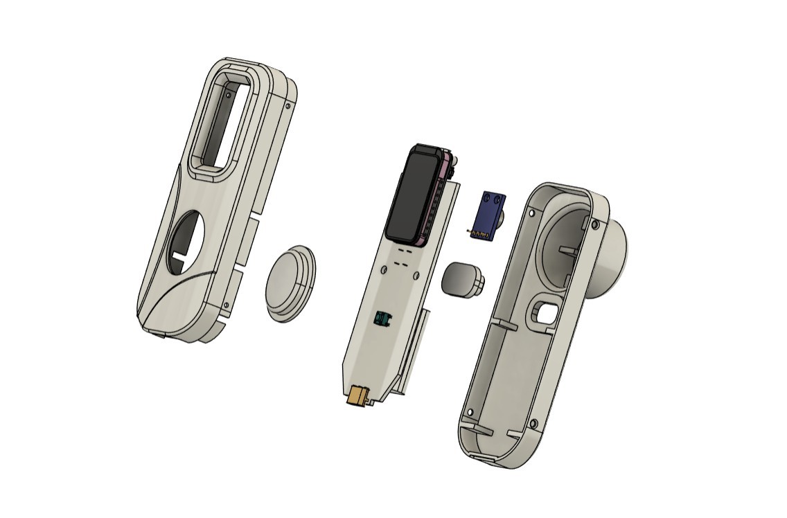
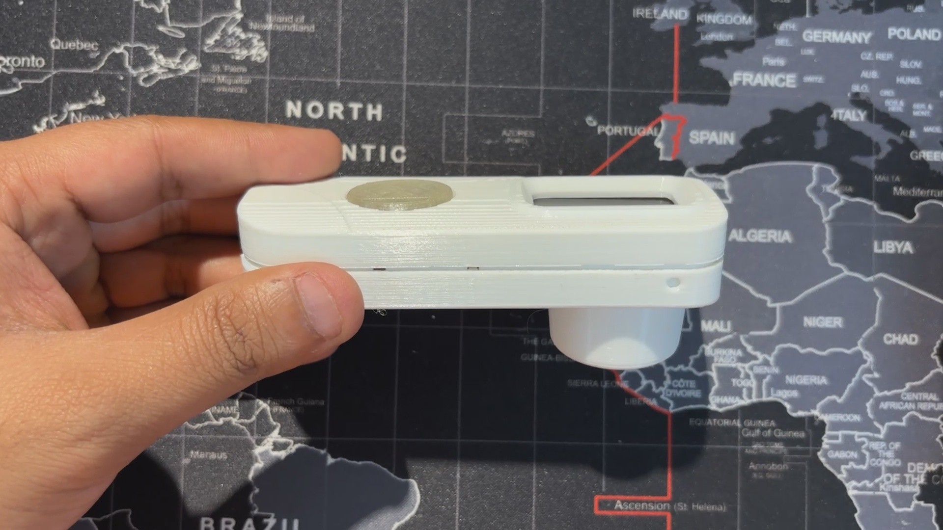
Using the design of our original Medic Mini, we kept the overall idea but simplified the front. The three buttons were removed and replaced with a single elliptical‑shaped button with an actuator that presses the switch connected to GPIO18. The front enclosure remains almost the same, while the back enclosure was completely redesigned. A circular section was added to hold the temperature sensor securely and give the device a temperature gun‑like design.
Overall, the build consists of a front and back enclosure, along with two switch actuators, one for taking temperature readings and one for power ON/OFF.
Both enclosures were printed in high‑speed PLA on the Anycubic Kobra S1, while the switch actuators were printed in transparent PLA.
-
5ASSEMBLY PROCESS
![]()
![]()
![]()
![]()
![]()
![]()
![]()
![]()
![]()
![]()
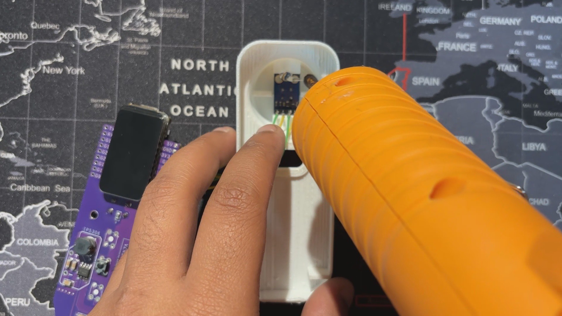
- We start the assembly process by adding the MLX90614 sensor in its location in the back enclosure, then use hot glue to secure it in place.
- Next, in the front enclosure, we add the switch actuator in position.
- The main circuit is then flipped over and placed in its slot in the front enclosure, secured with two M2 screws.
- The switch actuator for the power ON/OFF button is placed in its position in the back enclosure, after which the front and back enclosures are joined together to close the device.
- Finally, using the four mounting holes provided around the perimeter of the design, we insert M2 screws to secure the front and back enclosures, completing the assembly process.
-
6TESTING
![]()
![]()
![]()
For testing, we started with a cold glass of Coke and measured the outer surface; it read 15.1°C.
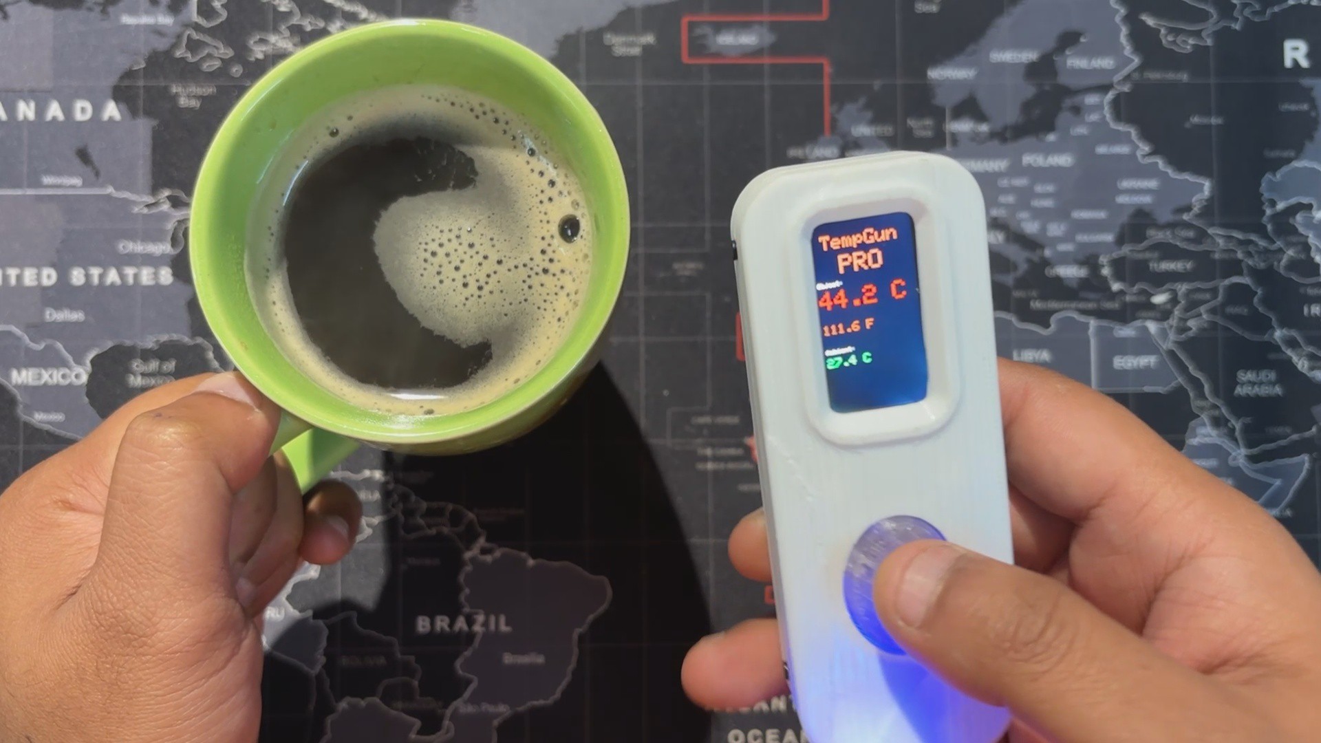
Next, for a hot test, we brewed some black coffee and measured the mug’s outer surface from the same distance, which came out to 44.2°C.
With TempGun Pro, we can measure all kinds of everyday items. The MLX90614 sensor works best at close range, with an ideal measuring distance of 2–5 cm.
For longer‑range measurements, the setup can be upgraded to the MLX90640, which offers a wider capability for thermal detection.
-
7Conclusion
![]()
TempGun Pro is a portable, battery‑powered temperature gun that’s easy to carry and delivers accurate close‑range readings. It covers a wide range from –70 °C to +380 °C with about ±0.5 °C tolerance, making it reliable for everyday use.
I now use it to check electronics, 3D printer beds, and other components during work, a perfect alternative while my Fluke is out for repair.
Overall, the project has been a success, and I’ve shared all related files so you can replicate it too. Just remember to give credit.
Thanks for reaching this far, and I will be back with a new project pretty soon.
Peace.
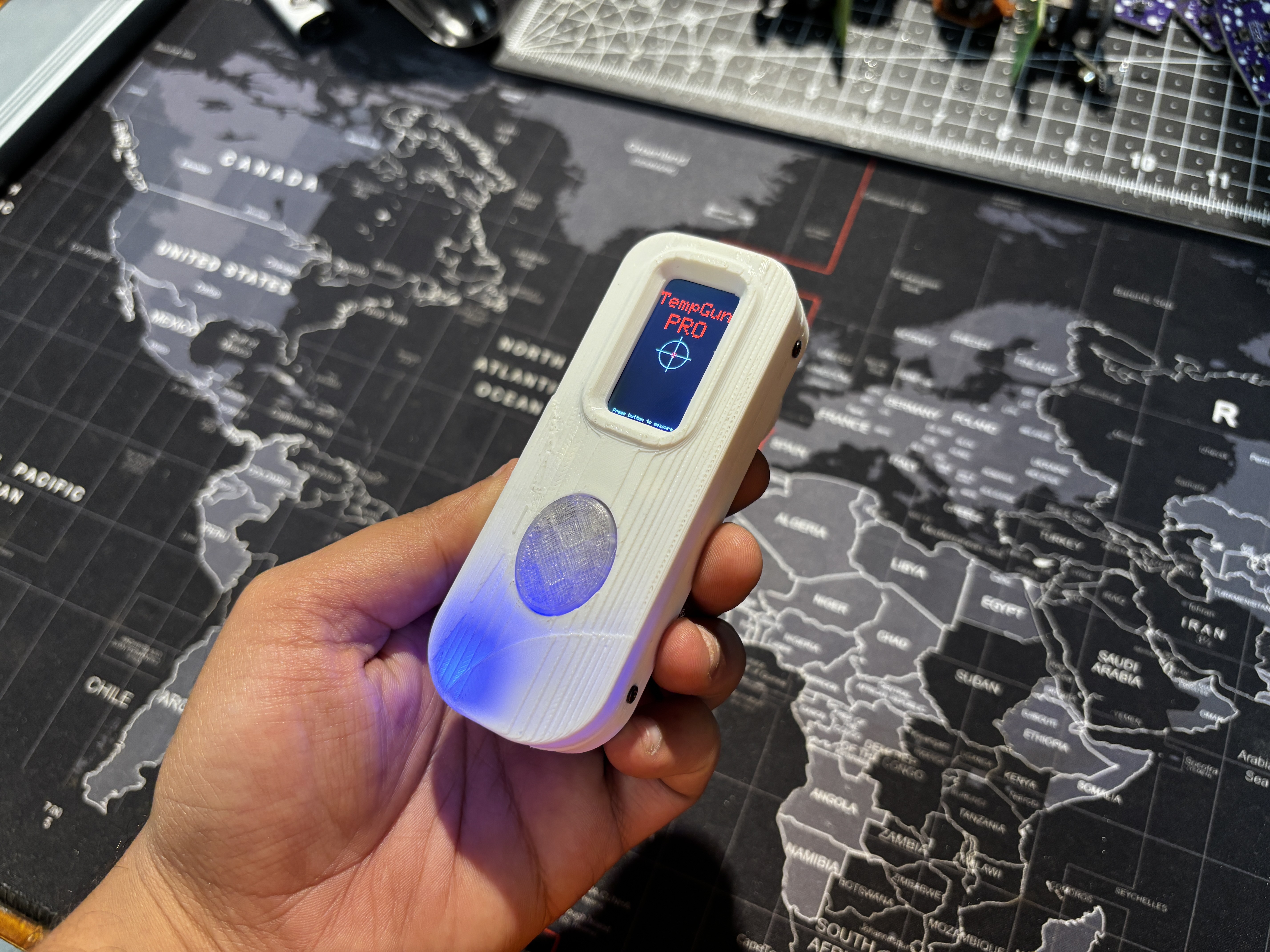
TempGun Pro
TempGun Pro is an open-source temperature gun powered by a custom ESP32 C6 devboard paired with an MLX90614 infrared temperature sensor.


Discussions
Become a Hackaday.io Member
Create an account to leave a comment. Already have an account? Log In.