 JohnsonFarms.us
A wireless pen plotter with simple, purpose-built code. Control it from any device with a web browser - draw on almost any device, hit send, and watch your creation plot in real-time.
It has custom firmware that does exactly what a WiFi pen plotter needs - nothing more, nothing less. The entire system is about 500 lines of C++ code that:
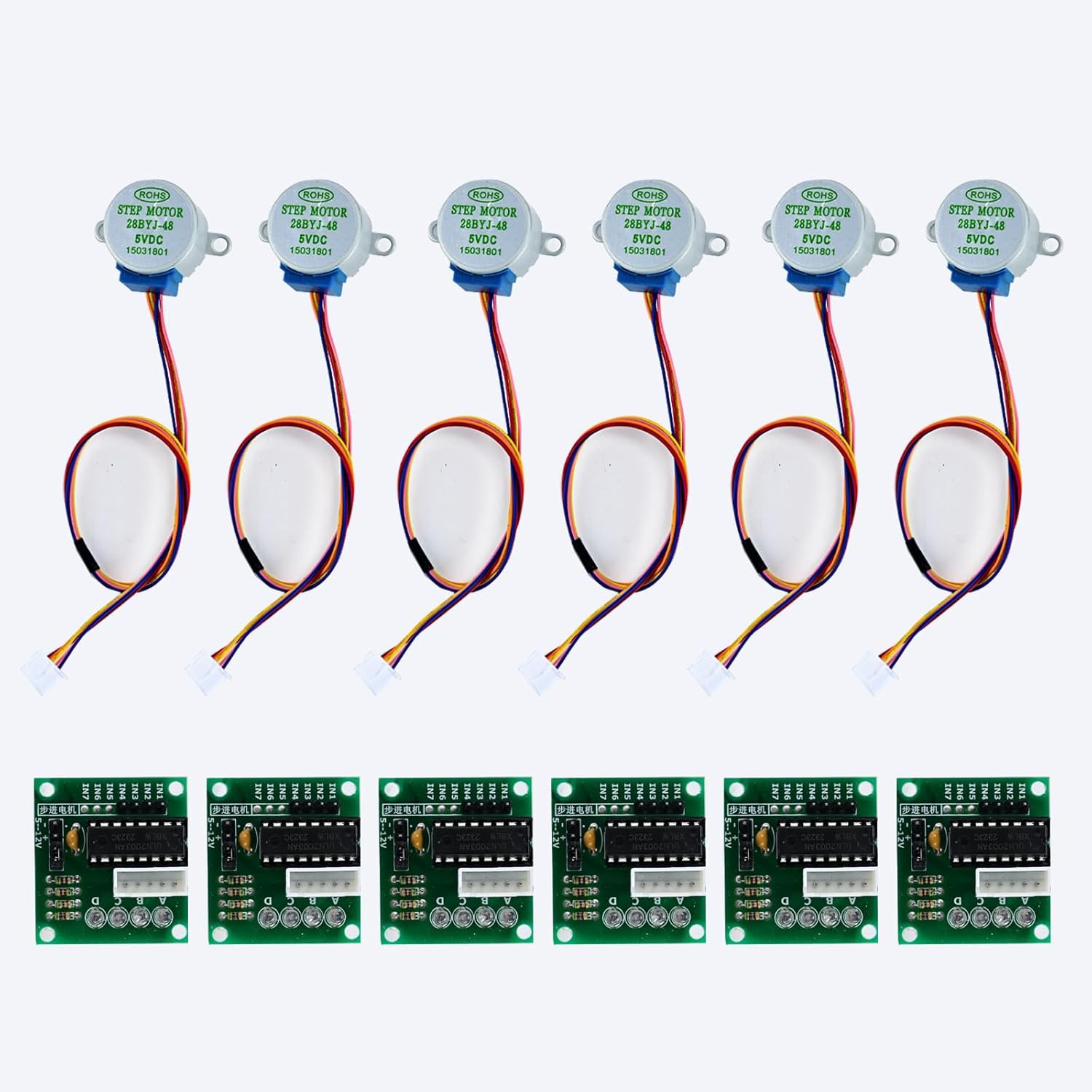
- Directly controls stepper motors: Uses half-step sequences to drive three 28BYJ-48 motors through ULN2003 drivers. No external motion control libraries needed.
- Serves a web interface: The entire HTML/CSS/JavaScript UI is embedded in the ESP32's flash memory using PROGMEM. No SPIFFS, no external files, no filesystem overhead.
- Parses basic G-code: Implements just the commands needed for plotting. The parser is simple, readable, and debuggable.
- Runs a WiFi access point: Powers on, creates "PlotterBot" network, serves interface at 192.168.4.1. That's it.
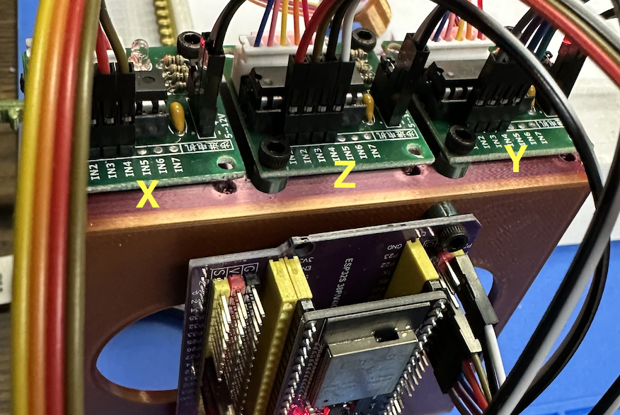
Hardware Setup
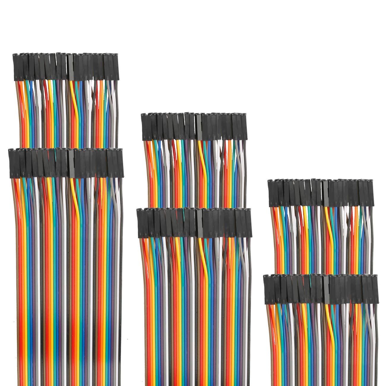
The electronics are intentionally simple:
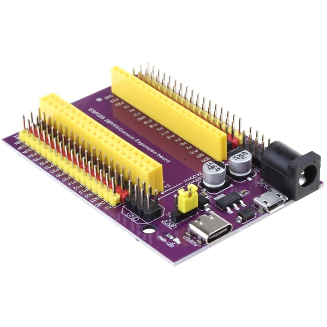
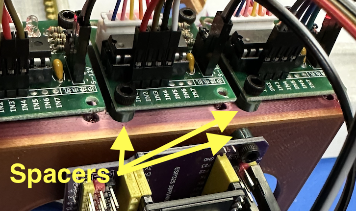
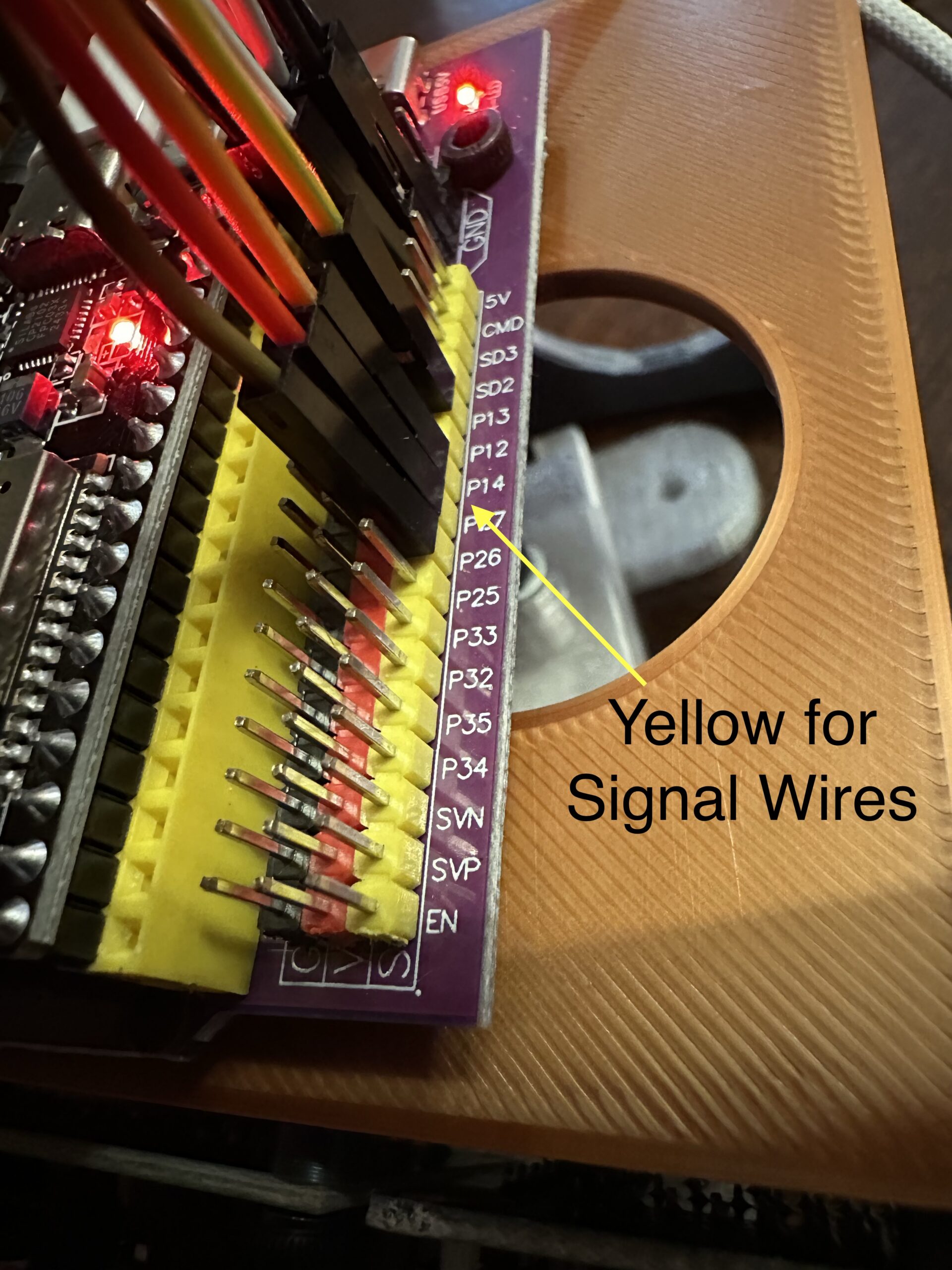
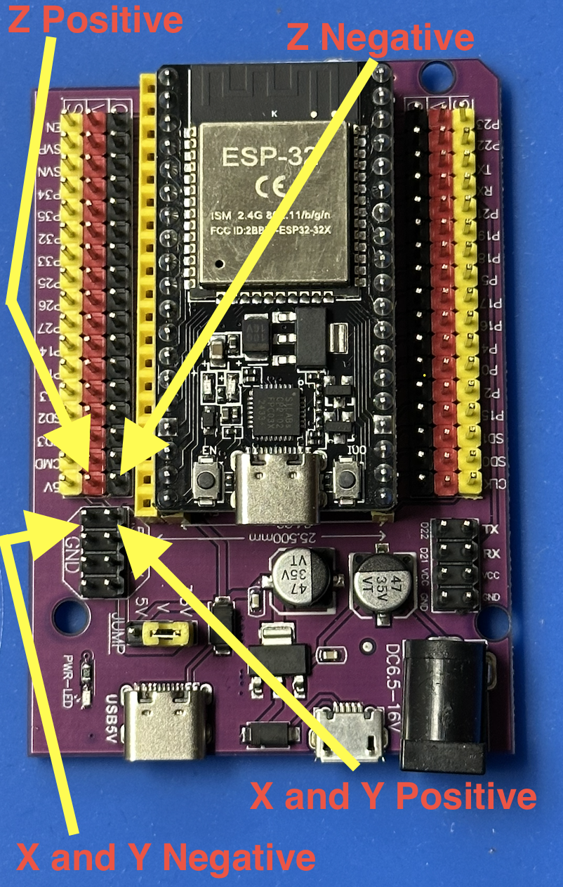
- ESP32 DevKit (any 38-pin variant)
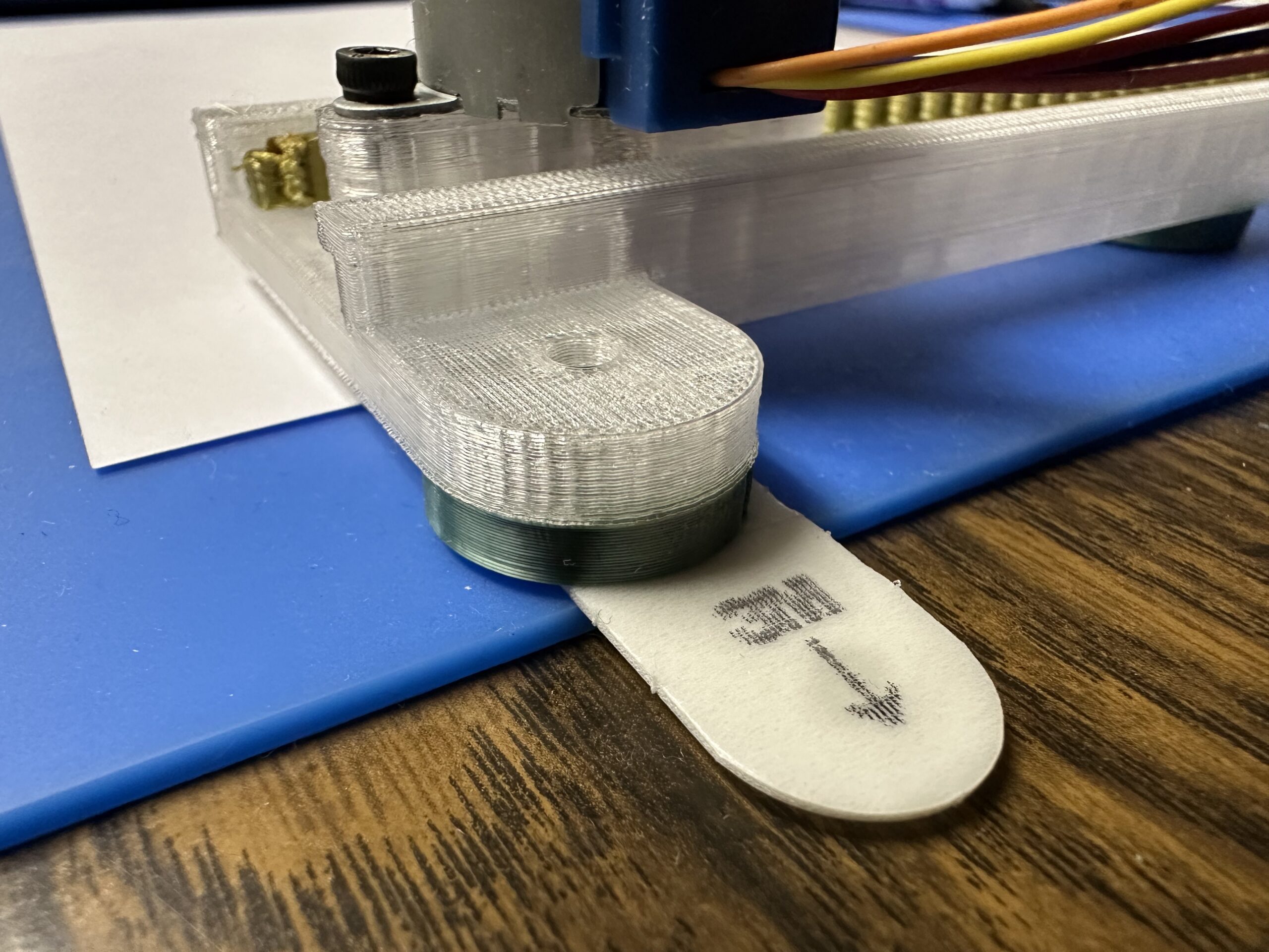
- 3× 28BYJ-48 stepper motors
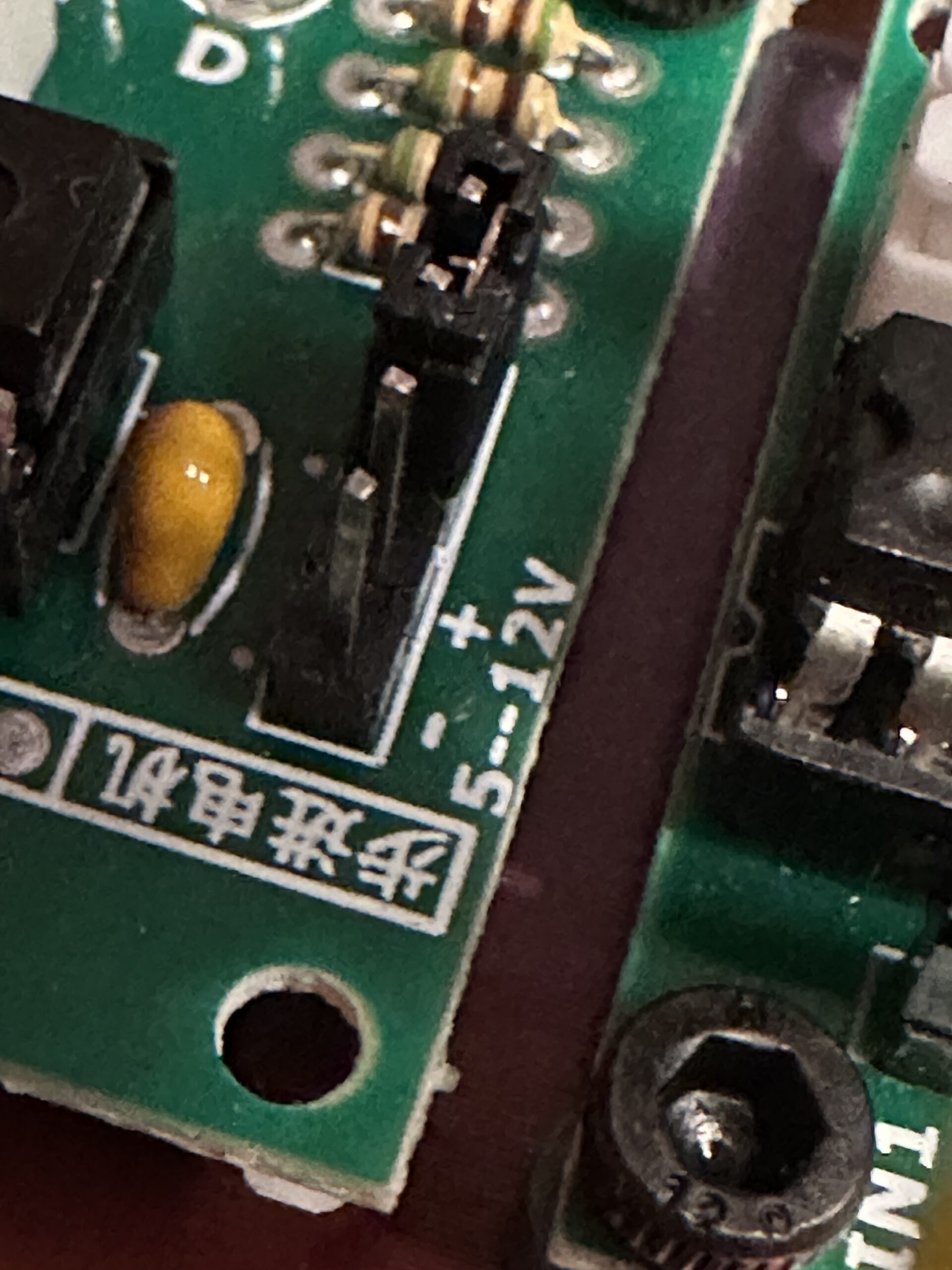
- 3× ULN2003 driver boards
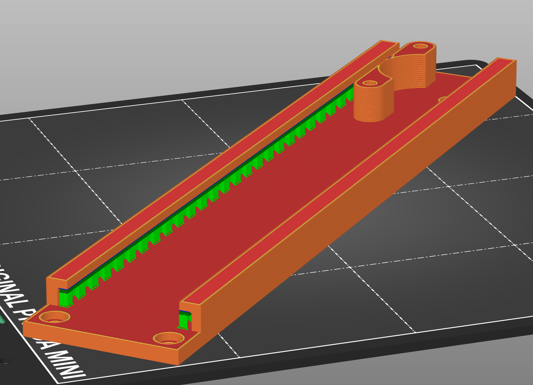
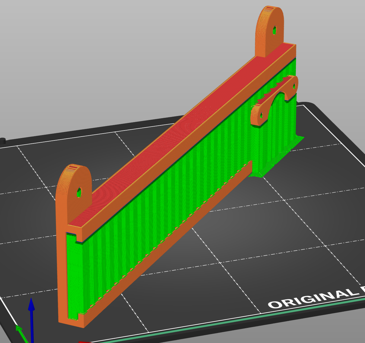
- 3D printed frame
Total electronics cost: under $15 if you shop around.
Software Architecture
Motor Control (motor_control.h): Direct GPIO manipulation using half-step sequences. Simple variables track current position in mm, and a basic moveTo(x, y, z) function handles motion planning with pen up/down logic and simultaneous X/Y movement. No fancy acceleration curves needed for a pen plotter running at reasonable speeds.
G-code Parser (gcode_parser.h): A straightforward string parser that handles G0/G1 moves, G28 homing, M3/M5 pen control, and M114 position reporting. It's intentionally minimal - unsupported commands are simply ignored.
Web Interface (web_interface.h): An MS Paint-style drawing canvas built with vanilla JavaScript and HTML5 Canvas API. Touch/mouse drawing with four tools (freehand, line, rectangle, circle), real-time preview, and client-side G-code conversion. The entire interface is stored as a string literal in PROGMEM - no filesystem required. The ESP32 serves it via a simple web server on port 80.
WiFi Setup (main.cpp): Configures the ESP32 as an access point with a captive portal that guides users directly to the interface when they power on.
The User Experience
- Power on the plotter
- Connect phone/tablet to "PlotterBot" WiFi (password: plot2025)
- Browser automatically opens interface, or navigate to 192.168.4.1 or plotter.local
- Draw something with your finger
- Tap "Send to Plotter"
- Watch it plot
No apps to install, no drivers, no configuration. Works on iOS, Android, laptops - anything with WiFi and a browser.
Technical Challenges Solved
Motor Synchronization: The cheap 28BYJ-48 motors have significant mechanical variance with 3D printed parts. A simple simultaneous stepping algorithm keeps X and Y axes synchronized by stepping them in the same loop iteration.
Calibration: The firmware includes easily-adjustable calibration constants like STEPS_PER_MM_X/Y/Z and X_INVERT/Y_INVERT to match your specific mechanics without rewiring. These are set to a safe limit for the 3d printed frame we are suing, but can be fine tuned or scaled as desired.
Touch Interface: Careful handling of both mouse and touch events with proper coordinate translation accounting for canvas scaling. The interface tracks drawing state and converts gestures to shapes in real-time.
Memory Constraints: The entire web interface had to fit in ESP32 flash. Minimal HTML/CSS/JS and no large libraries kept the embedded interface to ~15KB.
Why This Matters
This project helps demonstrate you don't need complex CNC firmware for every motion control application. Sometimes a simple, purpose-built solution is better than a general-purpose tool.
The code is intentionally readable and well-commented. If you want to understand how stepper motor control works, how to parse G-code, or how to build a web interface on an ESP32 - this is a great learning resource.
Plus, it actually works...
Read more »


 Taiwo
Taiwo
 Sergio García Sánchez
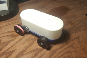
 Matthew James Bellafaire
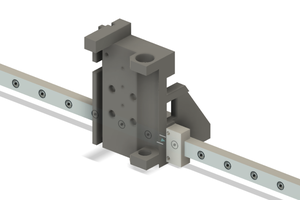
 arcade perfect