 JohnsonFarms.us
-
13d Printing
The 3d printed parts are all easy prints. Nothing too complicated and a fairly quick print as well. The test prints were done in PETG and PLA including intermixing components of both materials within a build and there were no issues. Print files are available at Printables.
You need one of everything, and multiples of the following:
- 2 x gear.stl
- 3 x x_frame_spacer.stl
- 9 x electronics_mount_spacer.stl
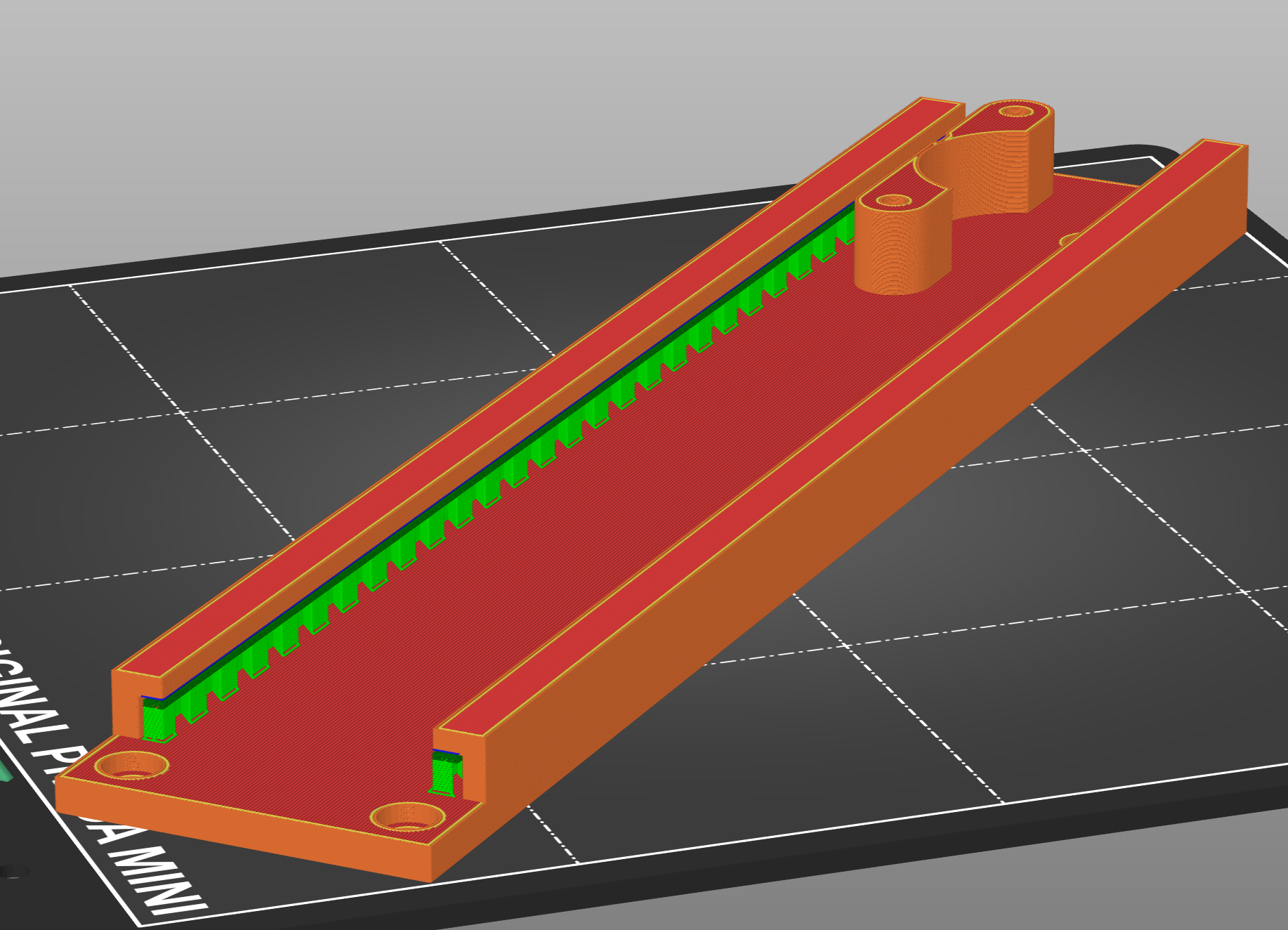
The only parts that need support are the x_frame.stl and y_frame.stl along the interior of the rail where the x_movement.stl and y_movement.stl slide within the frames. Snug supports were easiest to remove by running a small flathead screwdriver down the rail. See the image below for an example of supports.
![]()
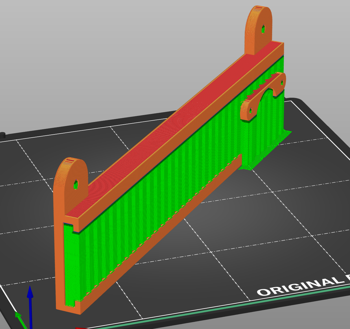
The parts can be printed on a printer as small as the Prusa Mini, but it does require some alternate orientation for the x_frame.stl to fit (everything else fits no problem). It needs turned onto onto an edge and rotated diagonal on the plate to fit. This is not ideal, but possible if it is your only option. See image below for an example of orientation for smaller build plates.
![]()
-
2Hardware Assembly
Frame Assembly
Courtesy of Maker101 on YouTube. Here is a simple breakdown of frame assembly.
The main 3d parts for the pen plotter frame are the same as this project. This makes for a nice assembly guide, but the glued part can also be screwed into place as well.
Since this was adapted from an existing project, the x_frame_spacers will need to be added to level out the frame. You can get away with two and just glue them directly under the screw holes for the x_frame piece. A third spacer can be added centered between the two directly under the x_frame if desired.
![]()
Electronics Mount
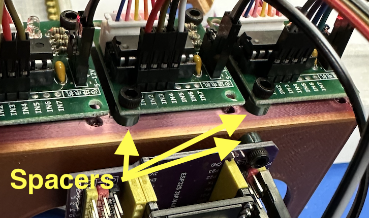
For the electronics, use the electronics_mount and the electronics_mount_spacers with M3 screws. See the photo below for an example. Just place the spacers between the boards and the mount.
![]()
Mounting Tip
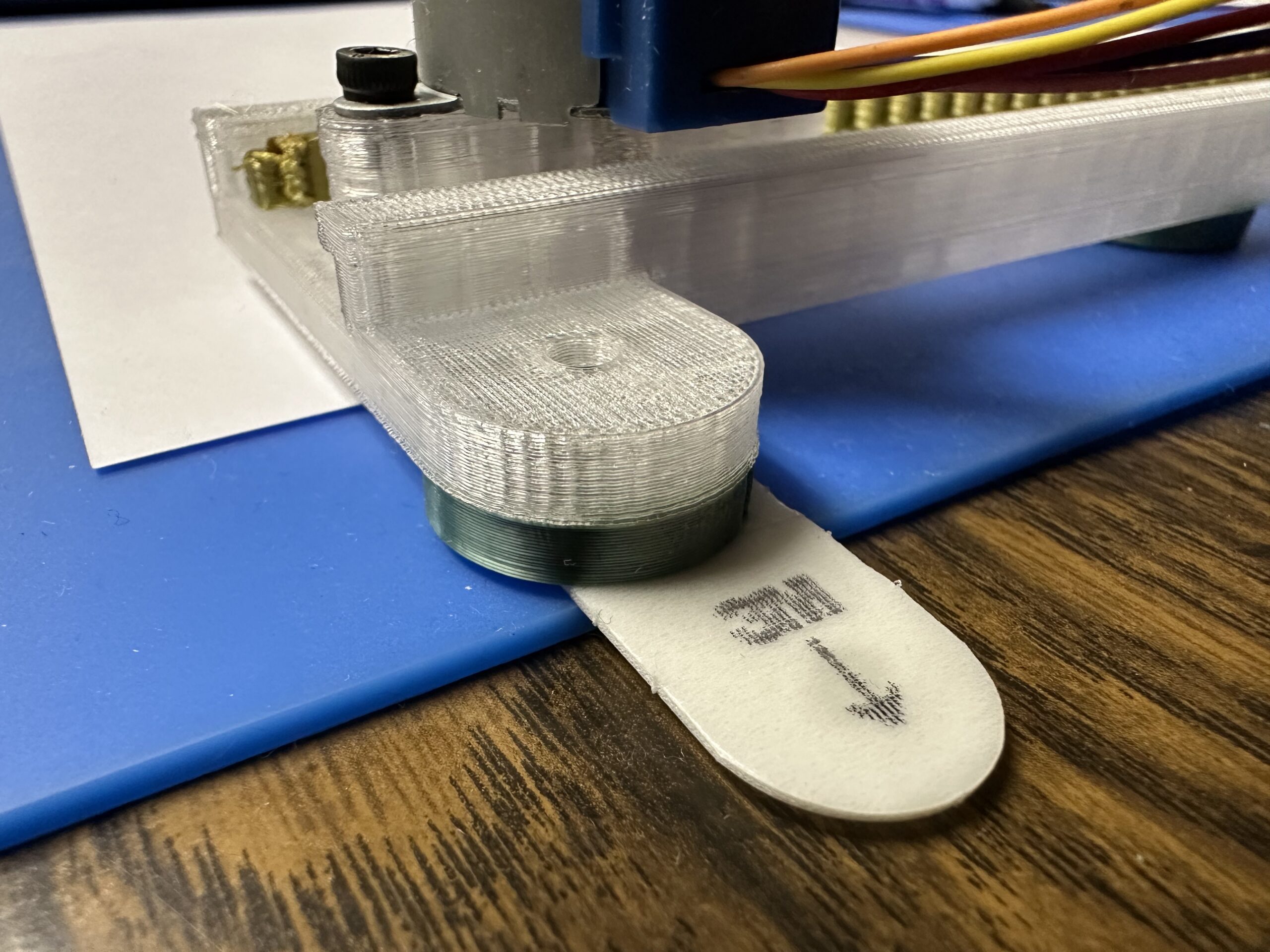
You do not have to screw the frame to a board, though that may be convenient depending on your use. We just used a couple removable command strips to stick it to a surface (you can see this in one of the above photos), in our case a silicone work mat. The mat has the added benefit of a bit of texture and squish which has helped hold the papers in place and allow for a bit of give for stiffer writing implements like ball point pens.
-
3Wiring
The wiring is pretty straight forward. However, caution is needed when connecting the power. The motor controllers are supposed to have reverse polarity protection, but experience has shown that to be false. So keep track of your negative and positive wires carefully.
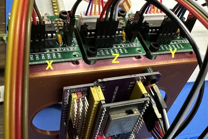
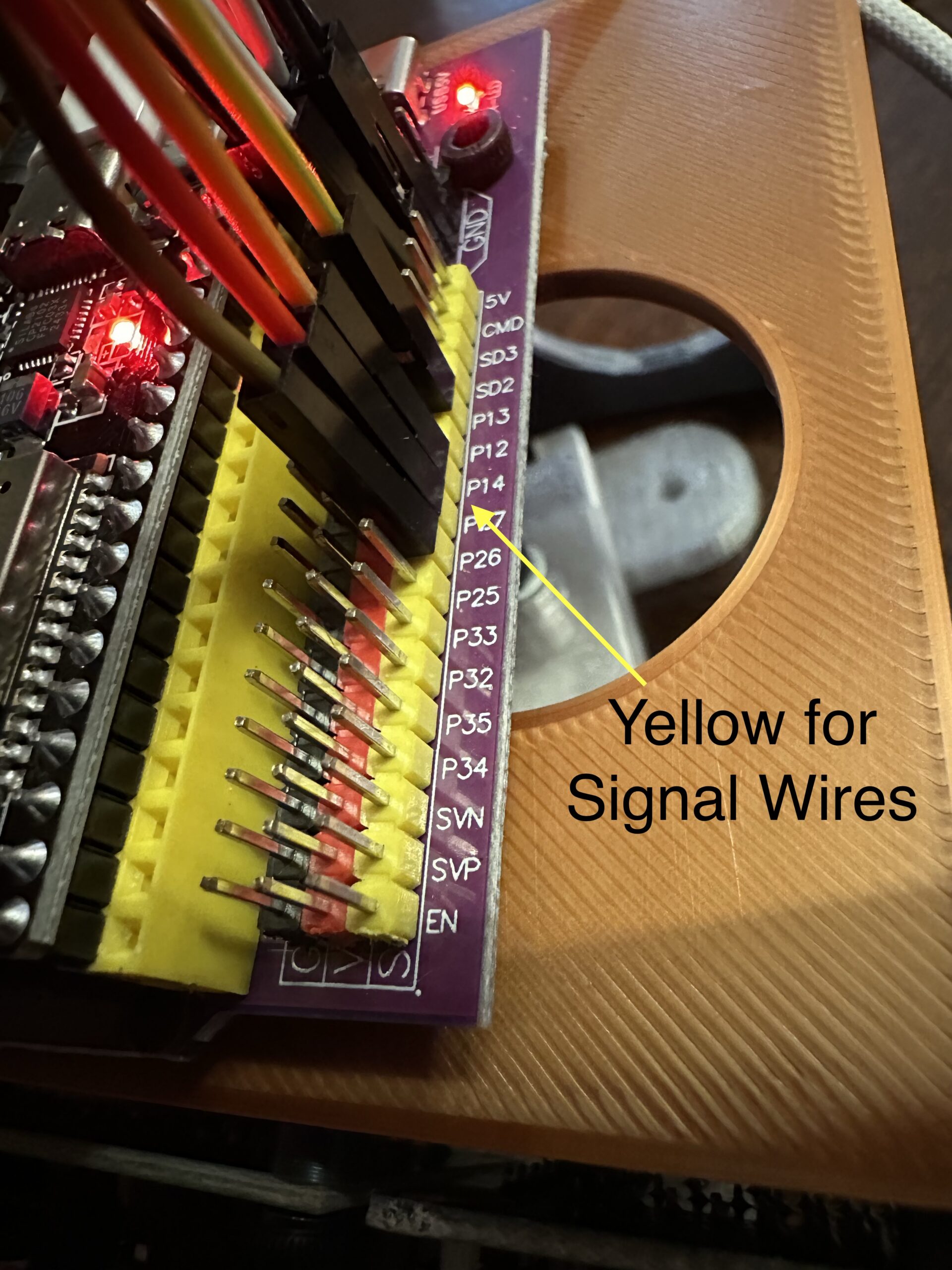
The motor wires just plug directly into the motor control boards, the plugs only fit one way so you can't mess this up. When you wire from the motor control board to the dev board you want to use the yellow column of pins. Just for reference the red column is positive voltage and the black is negative. So if you connect these signal wires to the red or black column it can fry your board.
![]()
X-Axis
GPIO 13 --> IN1
GPIO 14 --> IN2
GPIO 27 --> IN3
GPIO 26 --> IN4Y-Axis
GPIO 16 --> IN1
GPIO 17 --> IN2
GPIO 5 --> IN3
GPIO 18 --> IN4Z-Axis
GPIO 19 --> IN1
GPIO 21 --> IN2
GPIO 22 --> IN3
GPIO 23 --> IN4![]()
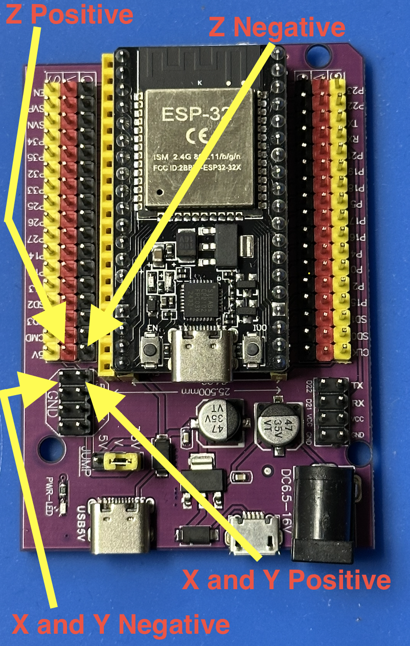
For the power we use the power plugs on the dev board for the X and Y and the 5v pinout for the Z, see image below. Be cautious here, the plugs are right near each other, but the plugs for the Z power are switched left right from the X and Y right next to it.
![]()
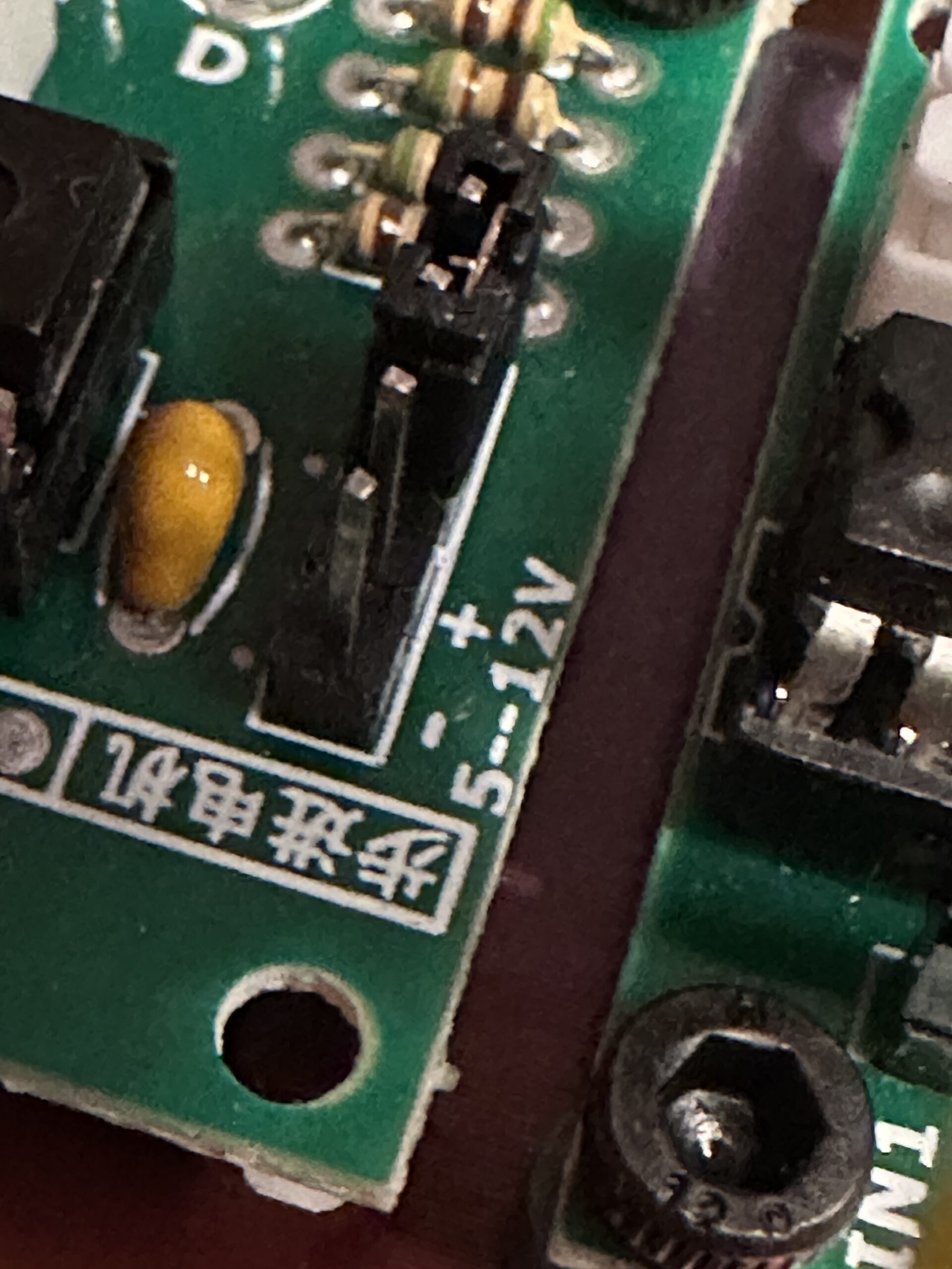
The positive and negative are clearly marked in the corner of the mortar control board.
![]()
-
4Software Installation
For the firmware installation you will need to use terminal mostly. The commands are simple but you will need to be able to navigate to the folder you downloaded the firmware to.
Get the Firmware
Option 1: Download Release (Recommended)
- Go to the Releases page on Github.
- Download the latest release (
.zipfile) - Extract the zip file to a folder on your computer (e.g.,
Downloads/pen-plotter-esp32)
Option 2: Clone from GitHub
git clone https://github.com/johnsonfarmsus/pen-plotter-esp32.git
cd pen-plotter-esp32
Prerequisites
Install PlatformIO Core:
Windows:
# Install using pip (requires Python 3.6+)
pip install platformio

# Verify installation
pio --version
macOS/Linux:
# Install using pip
pip3 install platformio

# Verify installation
pio --version
For detailed installation instructions, see the PlatformIO installation guide.
Upload the Firmware
Connect your ESP32 to your computer via USB, then navigate to the firmware folder and upload:
Windows:
cd pen-plotter-esp32/plotter_sketch
pio run --target upload
macOS/Linux:
cd pen-plotter-esp32/plotter_sketch
pio run --target upload
What happens during upload:
- PlatformIO detects your ESP32 and compiles the firmware
- Upload takes 30-60 seconds
- You'll see a "SUCCESS" message when complete
If upload fails:
- Press and hold the "BOOT" button on your ESP32, then try uploading again
- Some boards require holding BOOT + pressing RESET to enter programming mode
- Verify your USB cable supports data transfer (not just power)
-
5Operation
Setup
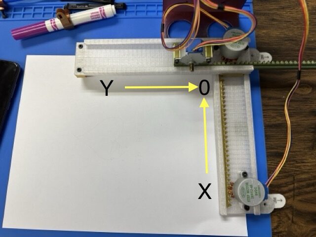
To get started the device needs to be at zero on the x and y and assumes the pen is in the down position. With the power off, you can just push each axis to the start position.
![]()
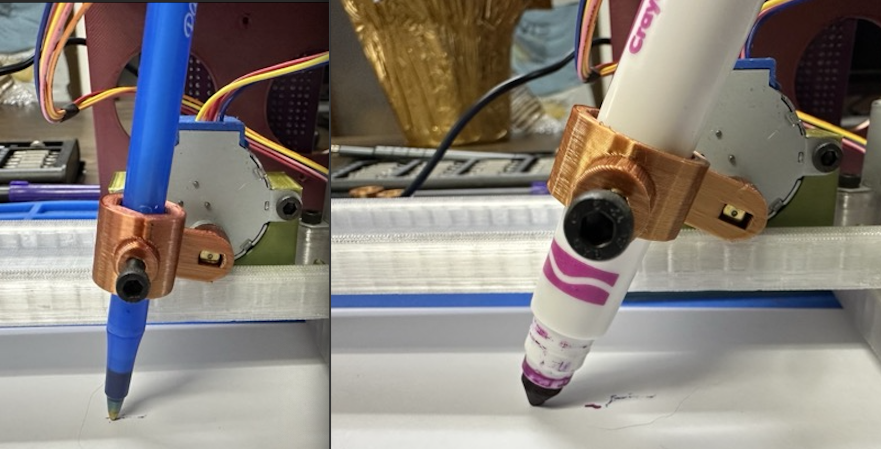
Use whichever pen holder best fits your desired writing utensil. If you use a ball point pen it helps for the down position to be more vertical while something like a crayola marker works well with a little angle. You can just turn the pen holder (z axis) by hand to adjust it to accommodate your pen.
![]()
We tend to print multiple pen holders and just leave the writing utensil mounted in the holder once we find a sweet spot and just swap holders and twist the z motor accordingly when we want to switch.
Once you have the pen adjusted you can hit "Pen Up" in the interface to raise the pen and load your paper.
Connect to PlotterBot WiFi
- SSID:
PlotterBot - Password:
plot2025
Open Web Interface
The web interface should automatically open, but if not open your browser to:
http://192.168.4.1orhttp://plotter.local![]()
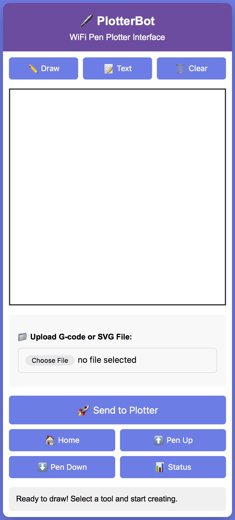
Draw and Plot!
- Select a drawing tool (Draw or Text)
- Create your design on the canvas or upload an SVG/G-code file
- Click "Send to Plotter" to start plotting
- Watch your creation come to life!
![]()
- SSID:
-
6Tuning and Troubleshooting
Coming Soon
Pen Plotter ESP32
3d Printed Pen Plotter with ESP32 and WiFi interface for under $20.
Discussions
Become a Hackaday.io Member
Create an account to leave a comment. Already have an account? Log In.