electronicsworkshops
Introduction
This system uses ESP32 modules to control street lights through a centralized IoT server.
Each street light is equipped with an ESP32 which connects to the same Wi-Fi network.
A central server or cloud dashboard sends commands to all street light control unit.
For Full Project:
https://electronicsworkshops.com/iot-based-automatic-street-light-controller-using-esp32/
Bill Of materials
1) ESP32 (one per light or per group)
2) Wi-Fi router (for network)
3) LED driver / MOSFET controlled by ESP32 PWM pin
4) Server (local Node-RED / cloud MQTT / Firebase / custom backend
5) LED PWM controlled
Working Principle
The IoT-based automatic street light controller using an ESP32 works by connecting each street light to a common Wi-Fi network, where a central server sends commands to control the lights. The ESP32 in each light receives these commands—such as ON, OFF, or brightness level—through MQTT or HTTP communication. Based on the command, the ESP32 activates its output pin to switch the light ON/OFF through a relay or MOSFET, and adjusts brightness using PWM signals to control dimming smoothly. This allows all street lights to be centrally managed in real time without any sensors, enabling efficient, remote, and programmable control of the entire lighting network.
Circuit Diagram
24 volt Led Driver Circuit
This 24V LED driver circuit uses a MOSFET-based switching stage controlled by a dedicated LED driver IC (U1) to regulate current through the LED load. The 24V supply is filtered using multiple capacitors (C4, C5, C7, C9) for stability, while an inductor (L1) and Schottky diode (D3) form the buck-converter output stage that drives the LED string. The driver IC senses LED current through the low-value resistor R10 and adjusts the MOSFET (Q1) gate accordingly to maintain constant current. Additional components—including soft-start and enable pins, compensation capacitors, and input filters—ensure stable operation, controlled startup, and proper current regulation. The result is a smooth, efficient, and protected constant-current LED driver suitable for 24V lighting applications.
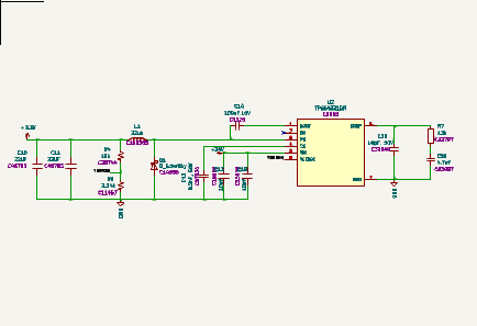
22 volt to 3.3 volt converter
This 22V-to-3.3V converter circuit uses the TPS54331 buck regulator (U2) to step the 22V input down to a stable 3.3V output. The input voltage is filtered by C13 and C18 before entering the regulator, while the high-frequency switching occurs at the PH pin, driving the inductor L1 to store and release energy for voltage conversion. The diode D1 provides a freewheeling path for inductor current during switching transitions. Output capacitors C10 and C11 smooth the 3.3V output, and the feedback divider formed by R4 and R5 sets the output voltage by feeding a scaled version of it into the VSENSE pin. The soft-start capacitor C12 controls the ramp-up speed of the regulator, and the compensation network (R7, C19, C20) connected to the COMP pin stabilizes the control loop. Overall, this circuit efficiently steps 22V down to 3.3V with good regulation and low ripple.
PCB Diagram

Order Directly from PCB WAY
I have...

 Hulk
Hulk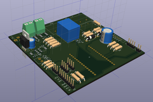
 Guillermo Perez Guillen