Key Components
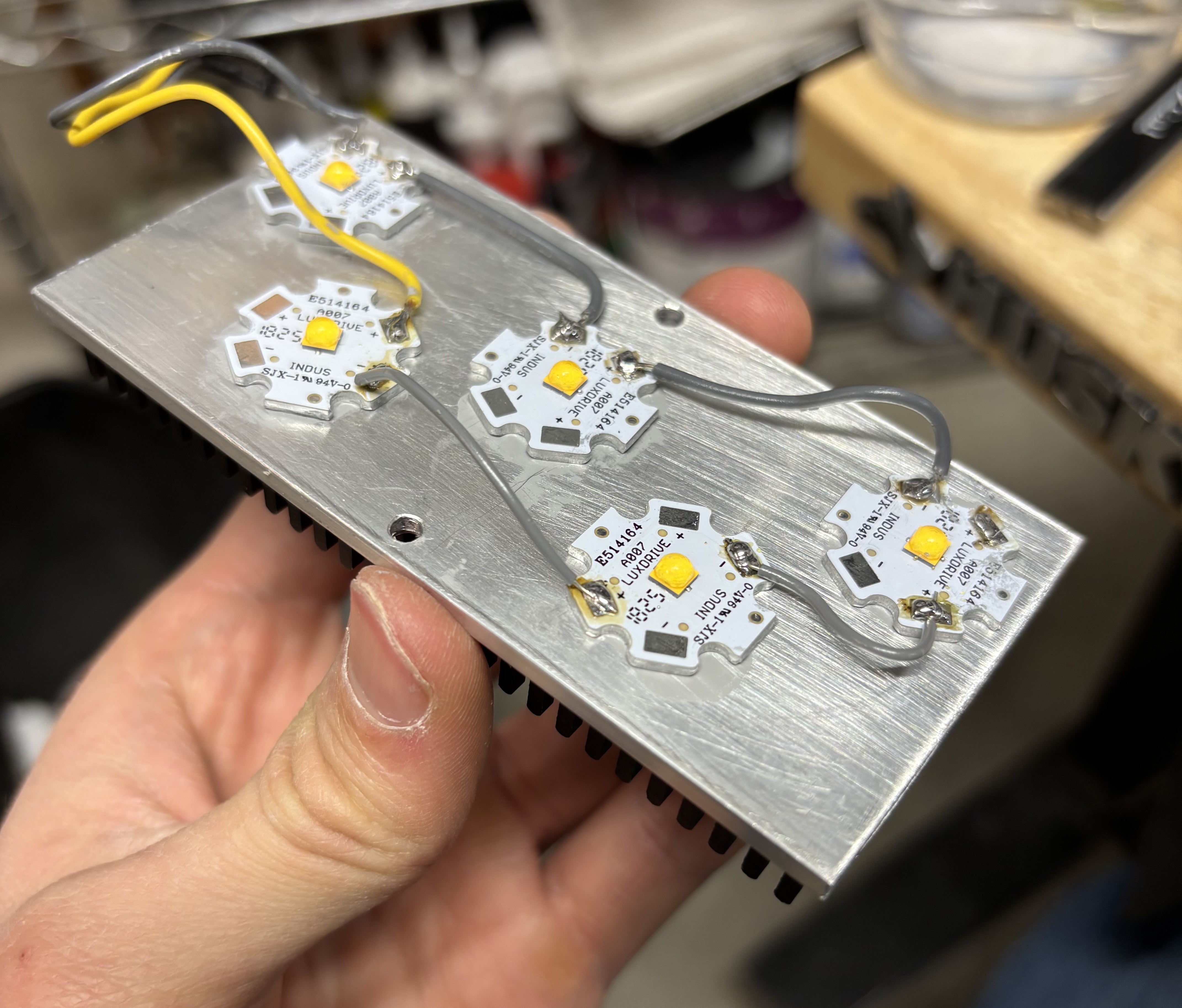
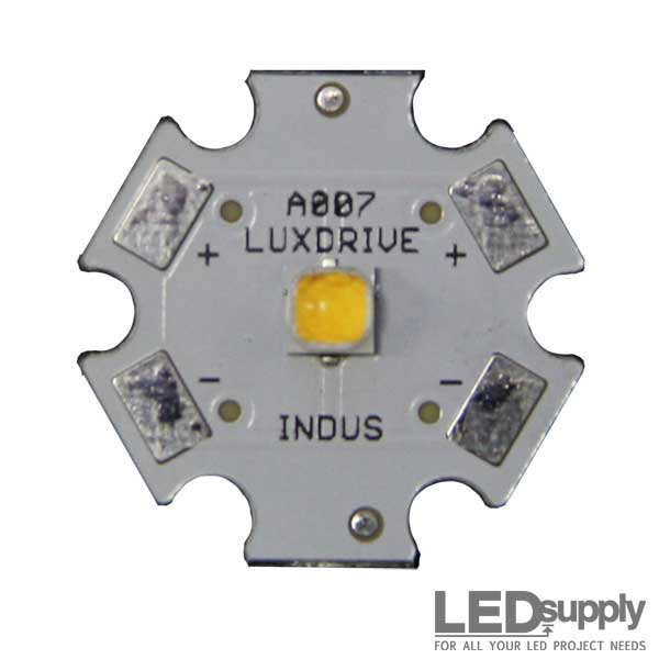
- 5x Cree XP-L 4000K LEDs: These are wired in series and being driven at 1A by the boost converter.
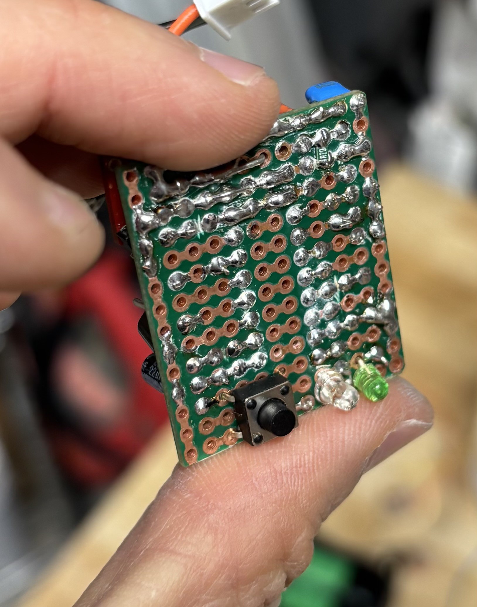
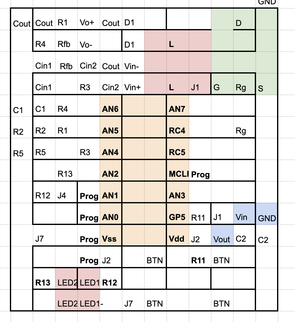
- Custom control board with a PIC16F1765 MCU and the boost converter circuit. Check out the project links for the firmware Github and protoboard design spreadsheet.
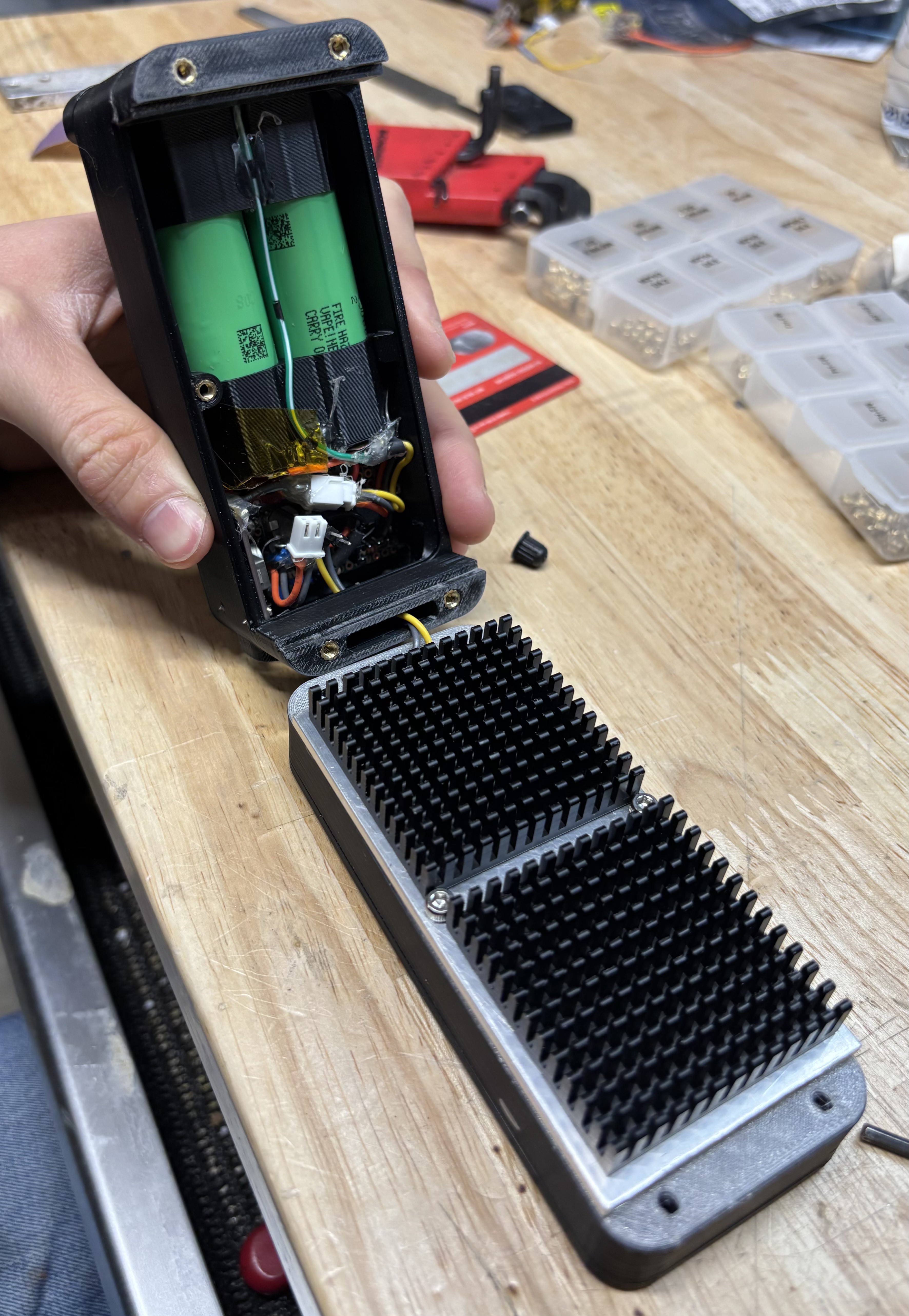
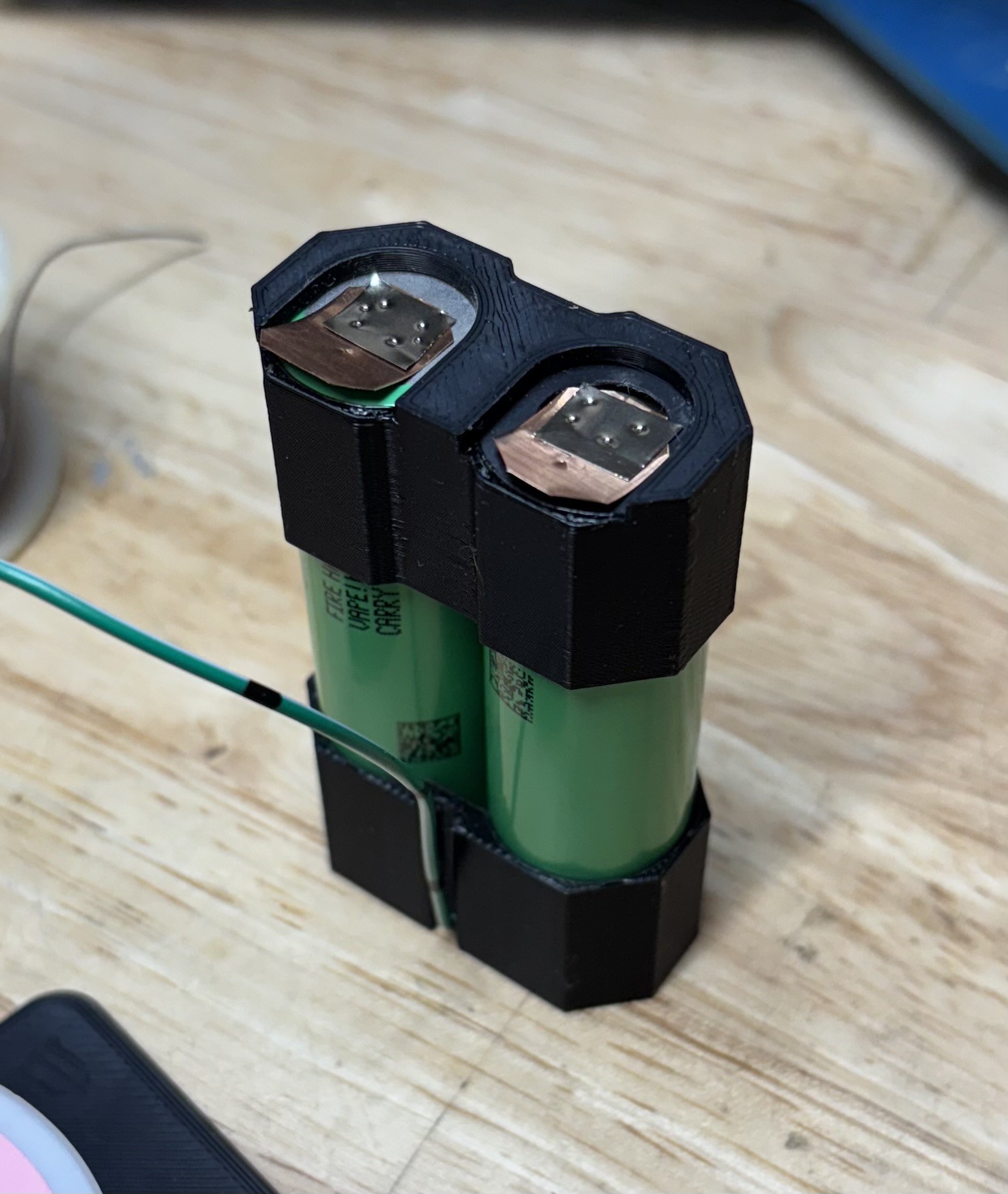
- 2x Samsung 50S cylindrical Li-Ion cells (18Wh each), wired in series
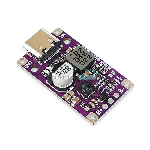
- USB-C 15W 2S battery charge and balance PCB (from eBay)
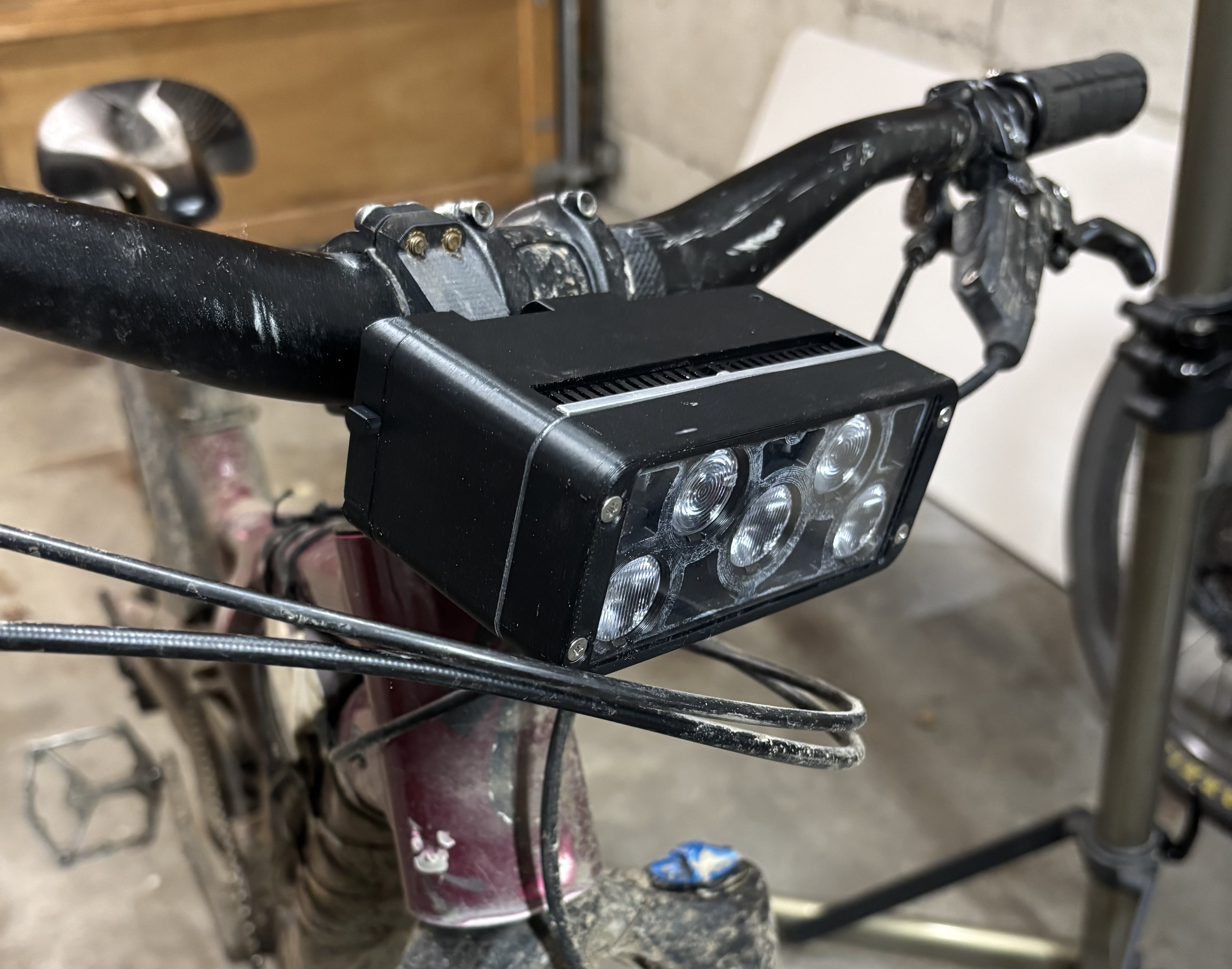
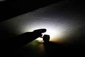
- 3x 30-degree by 15-degree elliptical TIR optics: These provide an oval-shaped beam pattern that puts more light to the sides.
- 2x 30-degree circular TIR optics: These provide a circular spot to give a bit of extra throw down the trail.
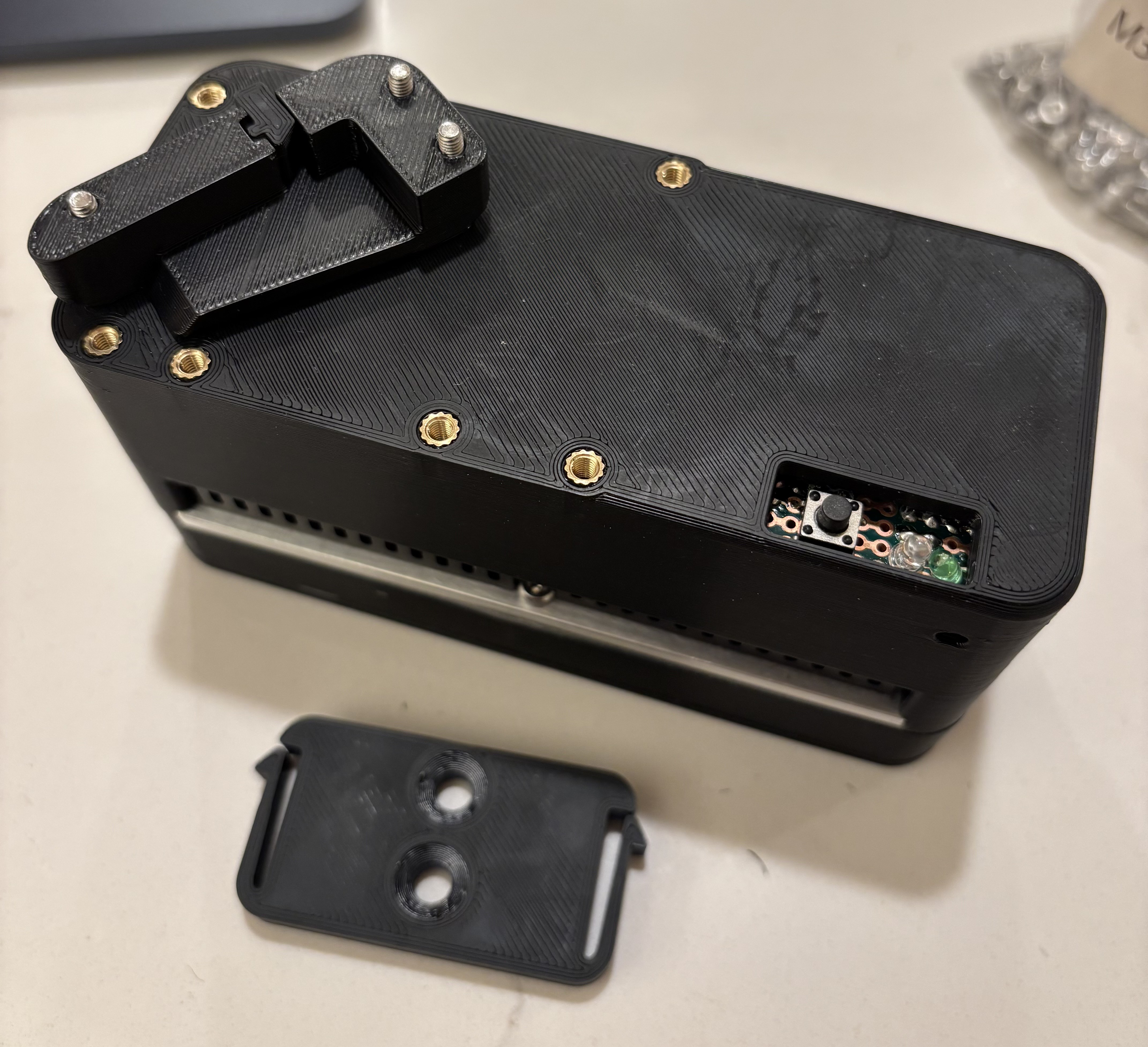
- ABS enclosure with a clear TPU gasket and status LED/button window and charge hole plug.
Check out the Components section for a full list with part numbers.
Photos
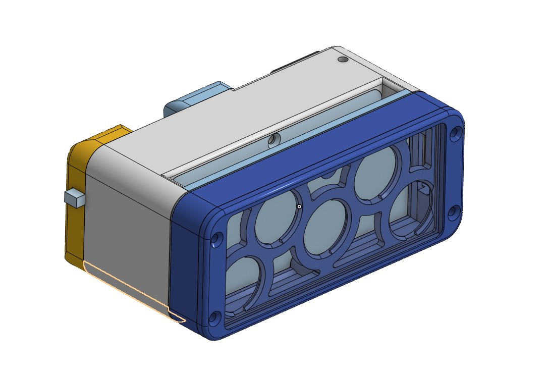

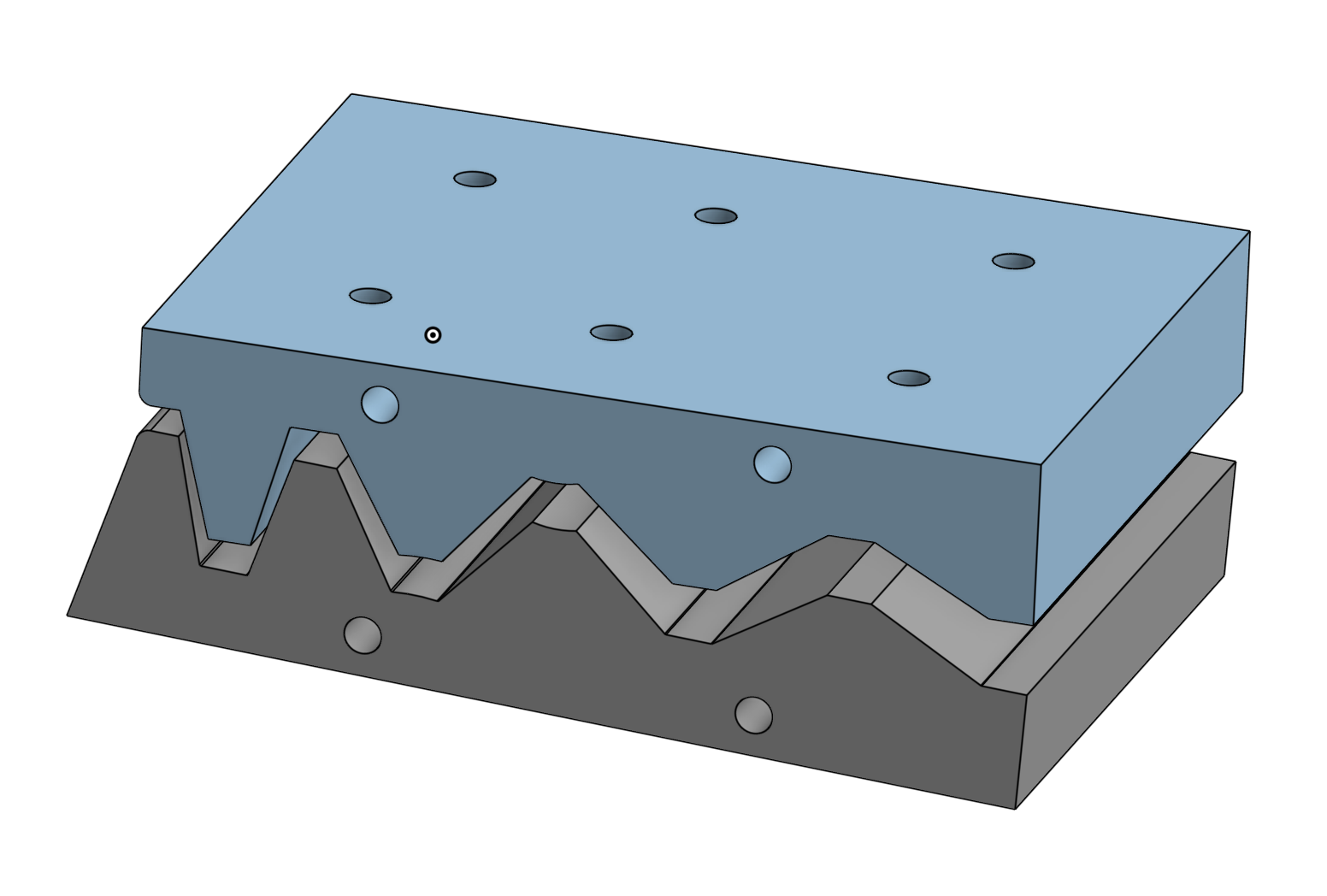
In the cross-section above, you can see the components of the enclosure and the two PCBs that are in there with the batteries. Here's the stackup from right to left:
- The bezel, in dark blue on the right, is split into two pieces so that the side that touches the plexiglass lens can be printed directly on the bed so it's nice and smooth.
- The front lens, in transparent gray, is a sheet of 3mm plexiglass that I scored and snapped into a rectangle. I solvent-welded the lens to the smooth face of the bezel with acrylic cement, which works fine for ABS as well. That provides a strong bond and nice waterproof seal.
- The LED mounting plate, light blue on the right, is a 1/8" thick 2" wide flat aluminum extrusion. The LEDs, TIR optics, and optic holders get sandwiched between this and the bezel.
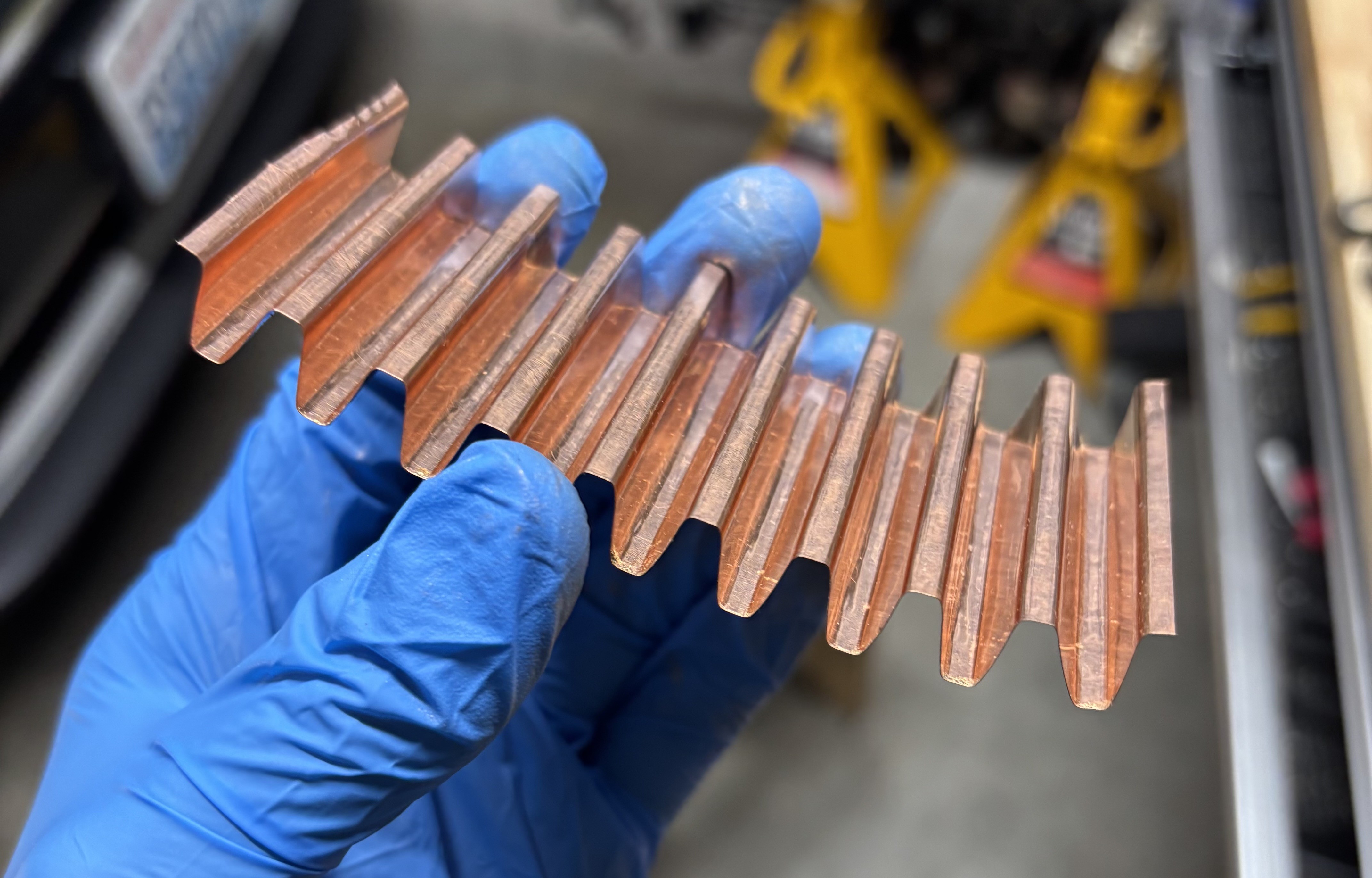
- The heatsinks aren't shown, but they're stuck to the mounting plate with thermal adhesive.
- The door, light blue on the left, slides in and out to provide access to the batteries and electronics.
- The USB battery charger PCB is the orange thing on the bottom
- The boost/UI PCB is orange on the left
- The dark gray thing is the transparent TPU window that lets you see the status LEDs and press the power button.
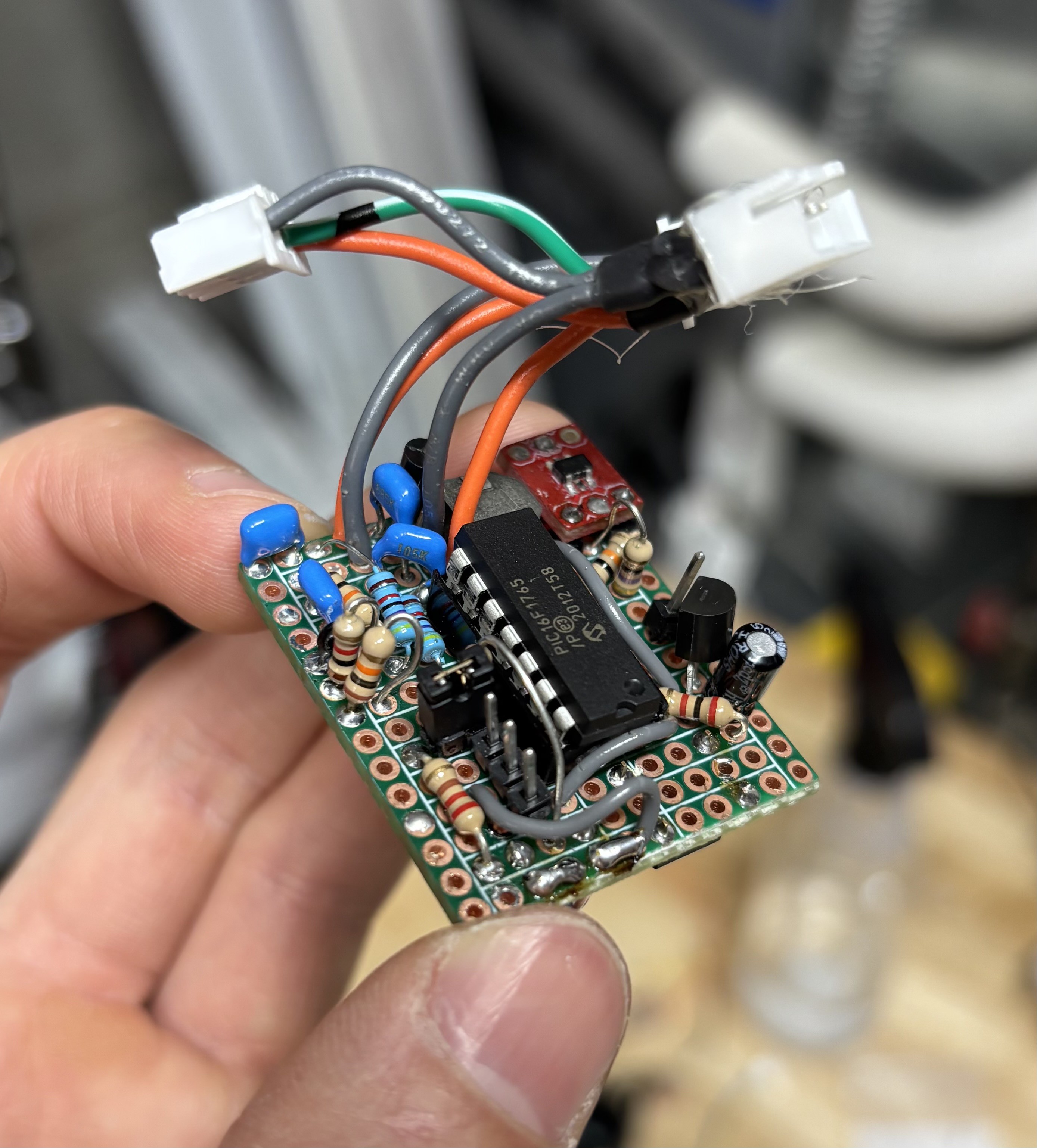
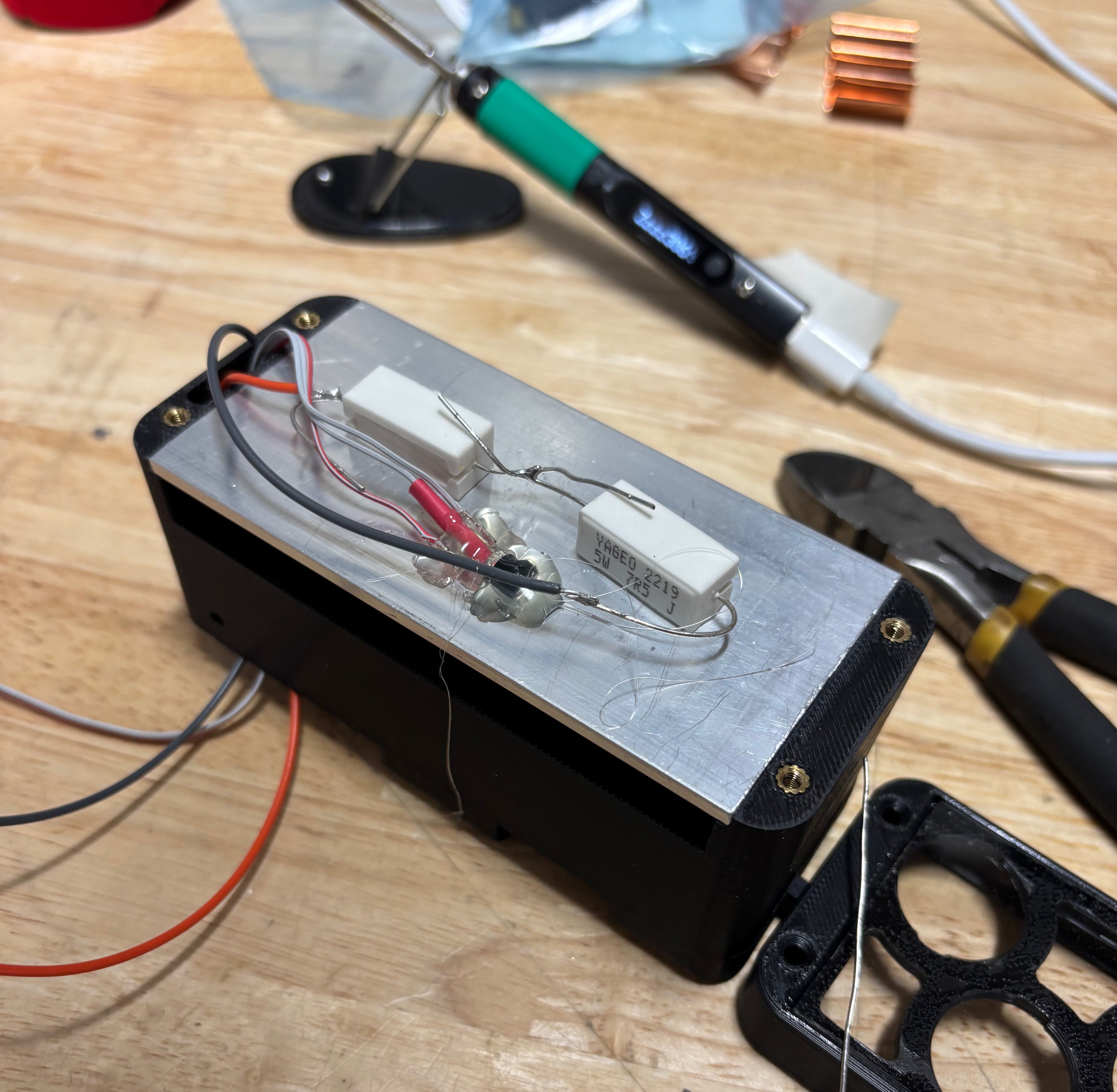
The LED driver is a standard boost converter topology, plus a 0.2-ohm current sense resistor between the LED- and ground. It takes 6.6V-8.4V from the battery and converts it to ~15V/1A for the power LEDs. It took me a few iterations to get to this point, and by the end it became clear that a custom PCB would have served me better than a protoboard. But hey, it works!
The MCU switches the circuit at 150kHz, which is on the low side for a small boost converter, but keeping the frequency low was necessary to give sufficient PWM resolution to accurately regulate drive current. The PIC16F1765 has a couple pins with 100mA source/sink capabilities; these provide just enough current to directly drive the gate of the FET (in the upper right, on a Sparkfun SOT23-to-DIP breakout) without a dedicated driver IC.
Check out the Components section of the project for the PCB BOM and component values.

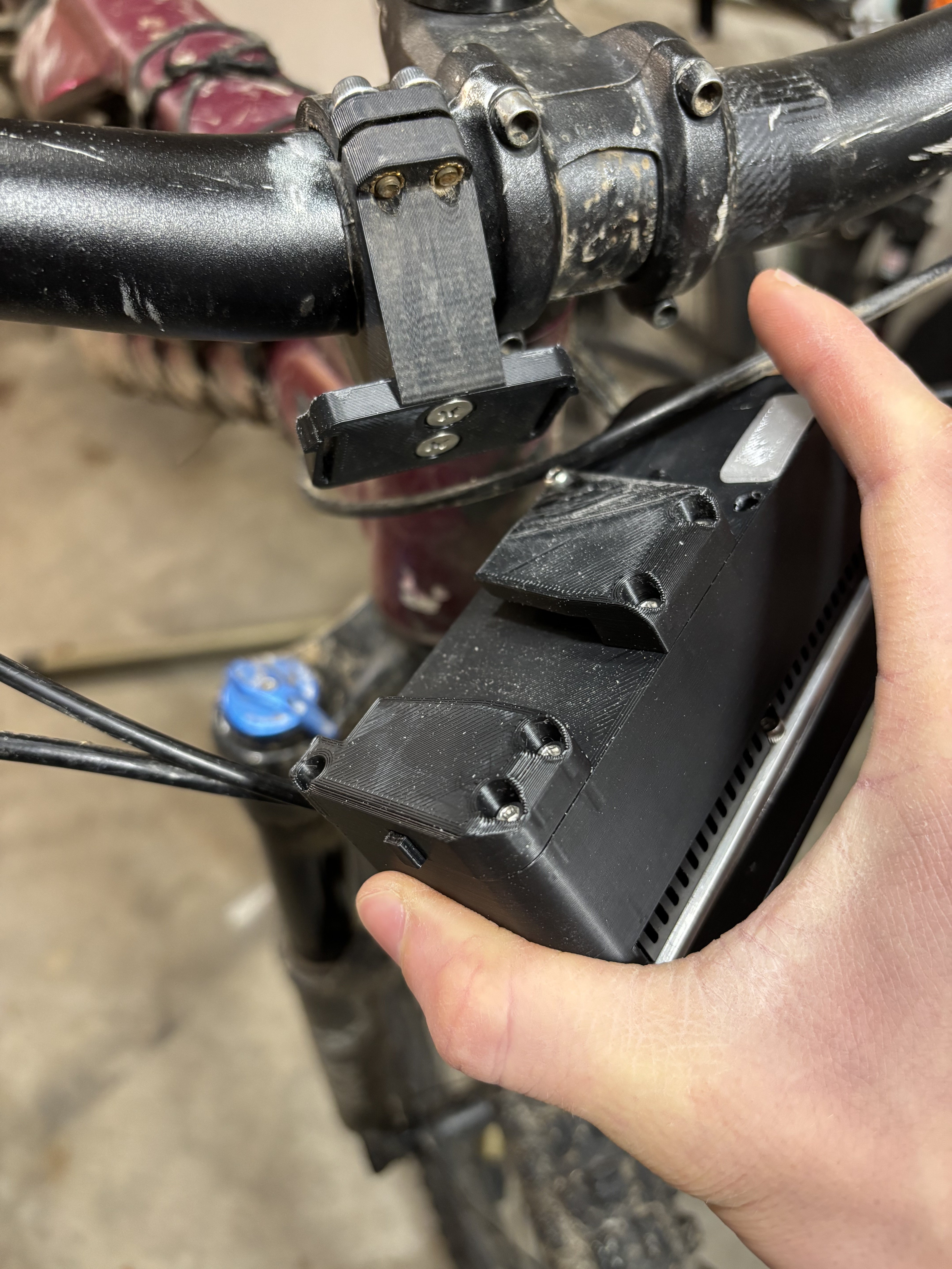
 Aluminum Top Mount")

 Lyon
Lyon
 Peter Fröhlich
 Said Alvarado Marin