-
DIY Corrugated Heatsink
3 days ago • 0 commentsAs soon as I got the light together, I realized the headlight was even chunkier than expected, coming in at almost exactly 400g. I'm no weight weenie, but almost 1lb is a bit on the hefty side to have hanging off the front of the handlebars. Plus, the more weight, the more stress on my 3D printed mount.
Original Hefty Heatsink
The most obvious suspect was the LED heatsinks. These are two off-the-shelf aluminum 46mm x 46mm chip heatsinks that I placed on the back of the aluminum plate. This part was one of the few heatsinks that I could find with a spec'd thermal resistance @ 0 airflow, but unfortunately no weight info was provided in the datasheet. They ended up being about 24g each, making up 12% of the total weight of the headlight. These are farther from the handlebar mounting point than the batteries, which at 140g are the other main contributor to weight. This means the heatsinks will have a larger moment of inertia about the mount axis and the steer tube axis, which translates to more stress on the mount and heavier steering.I looked around at other commercially available heatsinks and it seems like there aren't many that are designed to optimize for weight. I figured most engineers working on weight-optimized designs end up designing their own heatsinks, so I decided to do the same! Here's the current status.
![]()
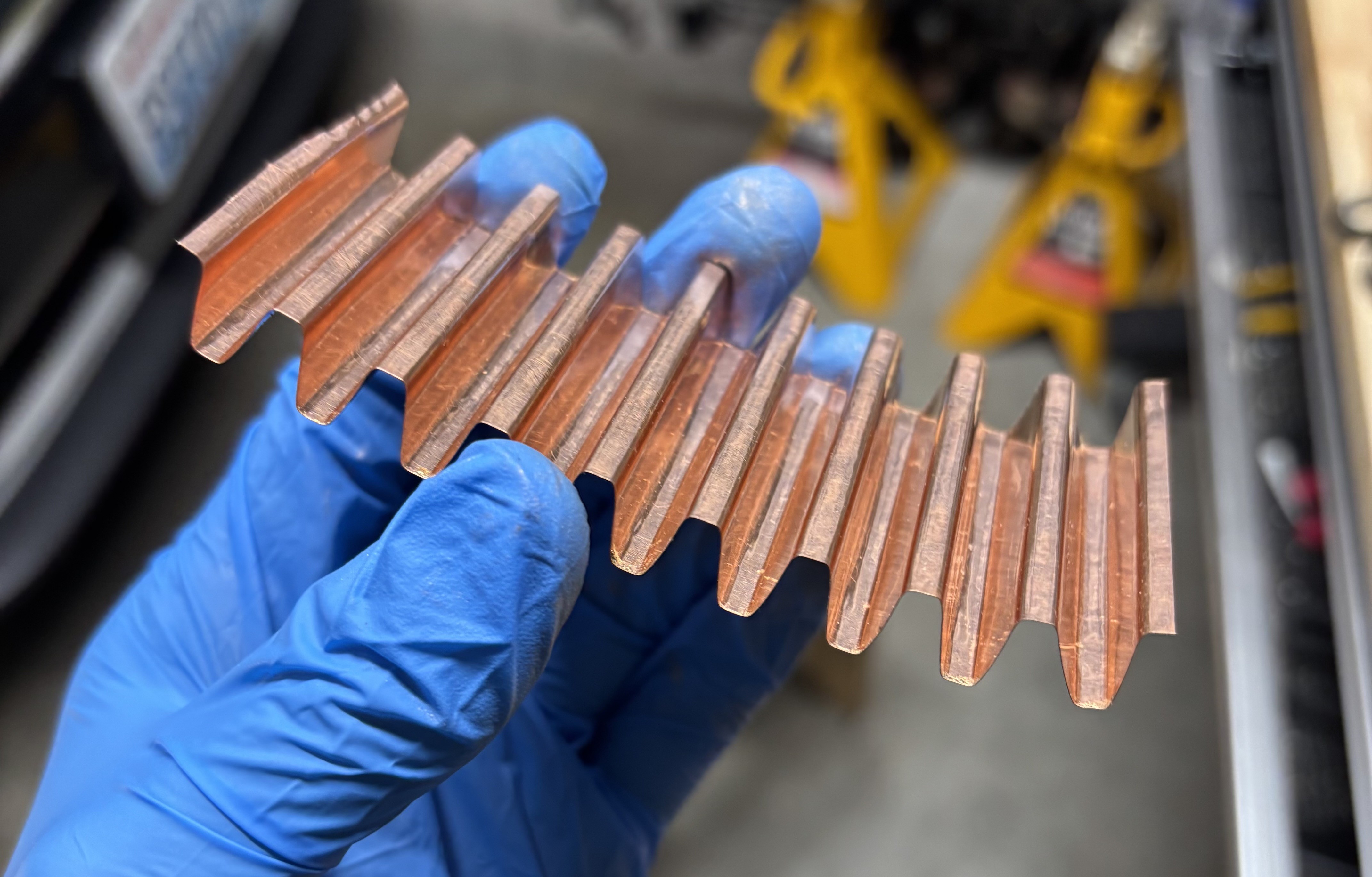
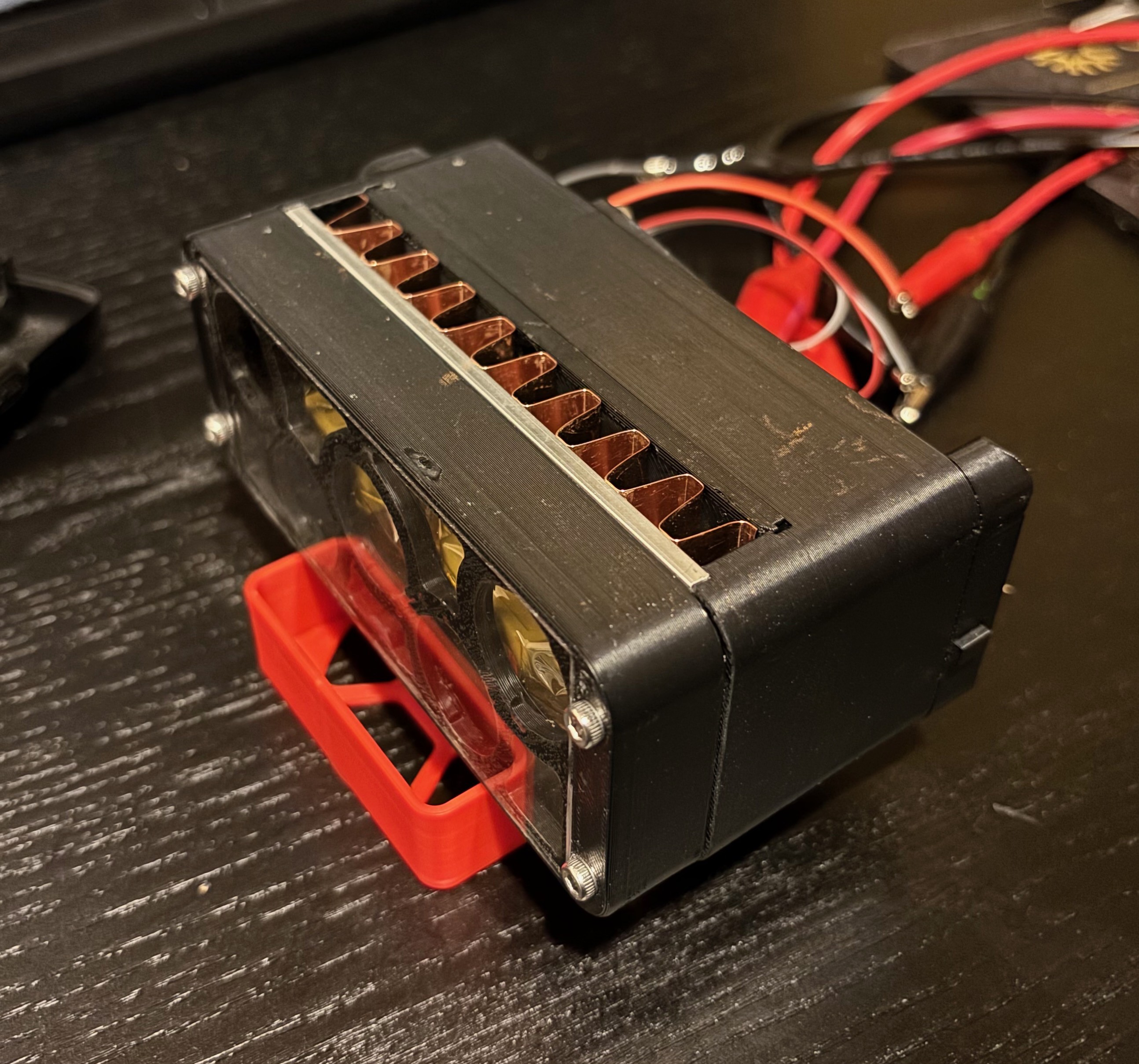
New, lightweight heatsink! I did the math and figured that a folded sheet of aluminum or copper, at least 0.1mm thick, should be thermally conductive enough and provide enough surface area to match the performance of the heatsinks currently in use. I conveniently had some 0.1mm copper sheet laying around from spot-welding my eBike battery cells. It's not gonna be very durable out in the open, but thankfully it safely resides in the cavity between the LEDs and the enclosure.
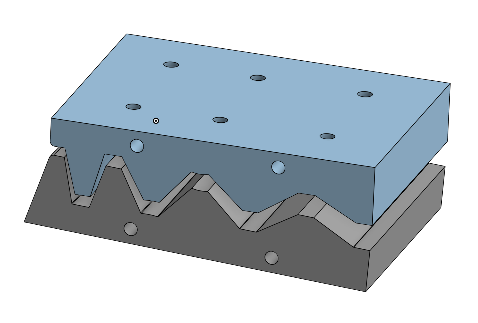
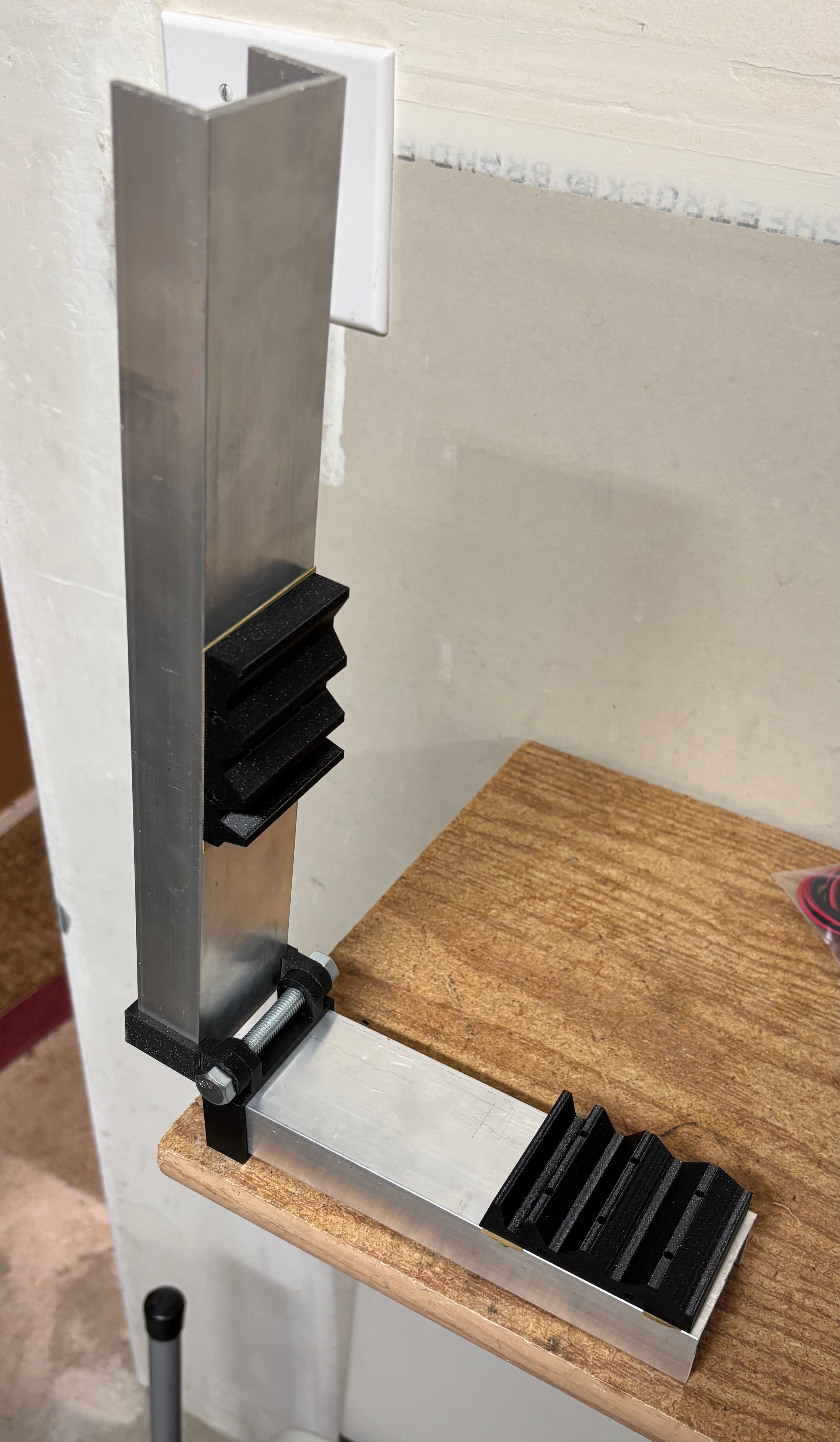
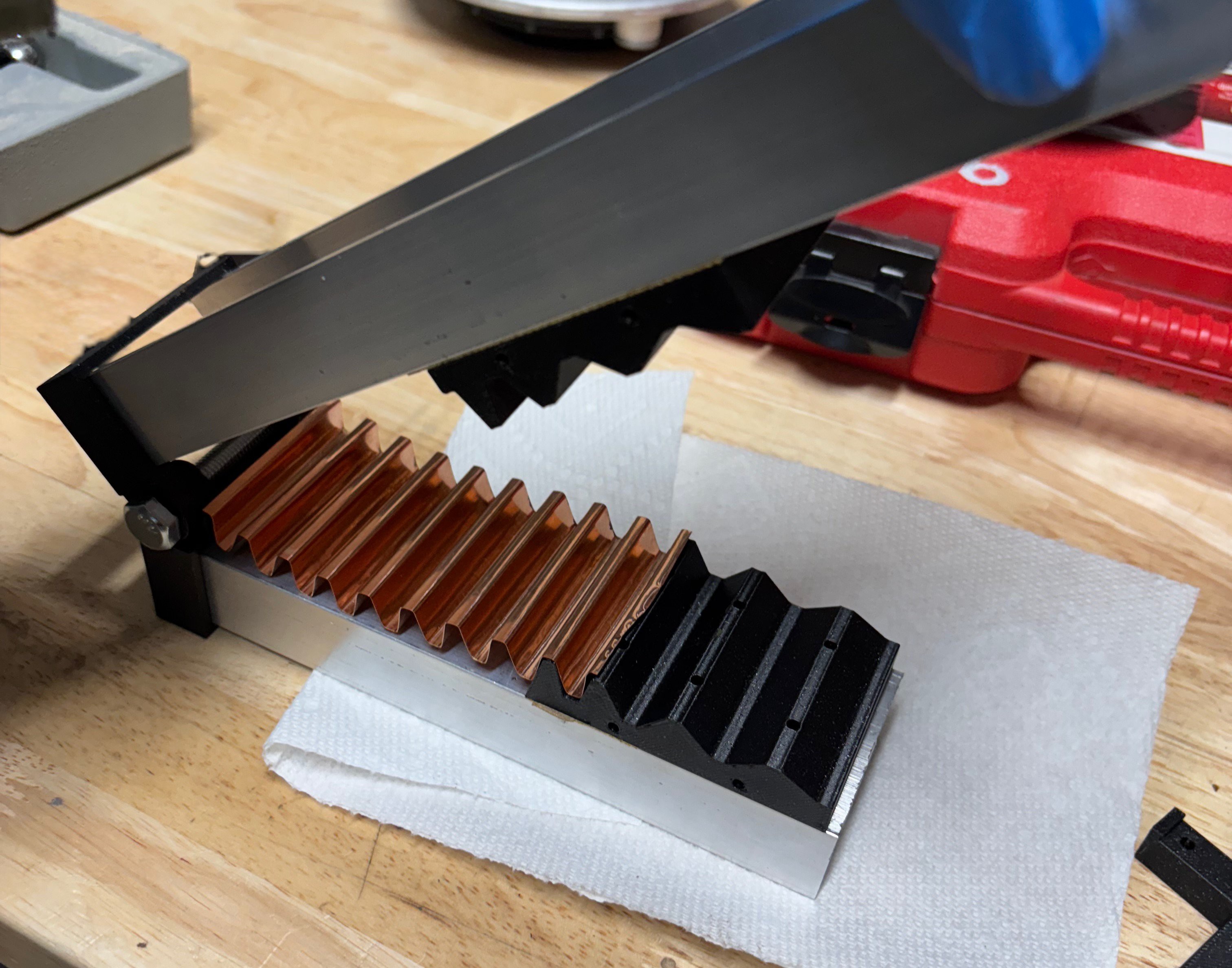
To keep my sponsors happy, I had to find a way to incorporate 3D printing, so I made a 3D printed die and stamping rig with leftover aluminum extrusions from the first version of the light.
![]()
![]()
![]()
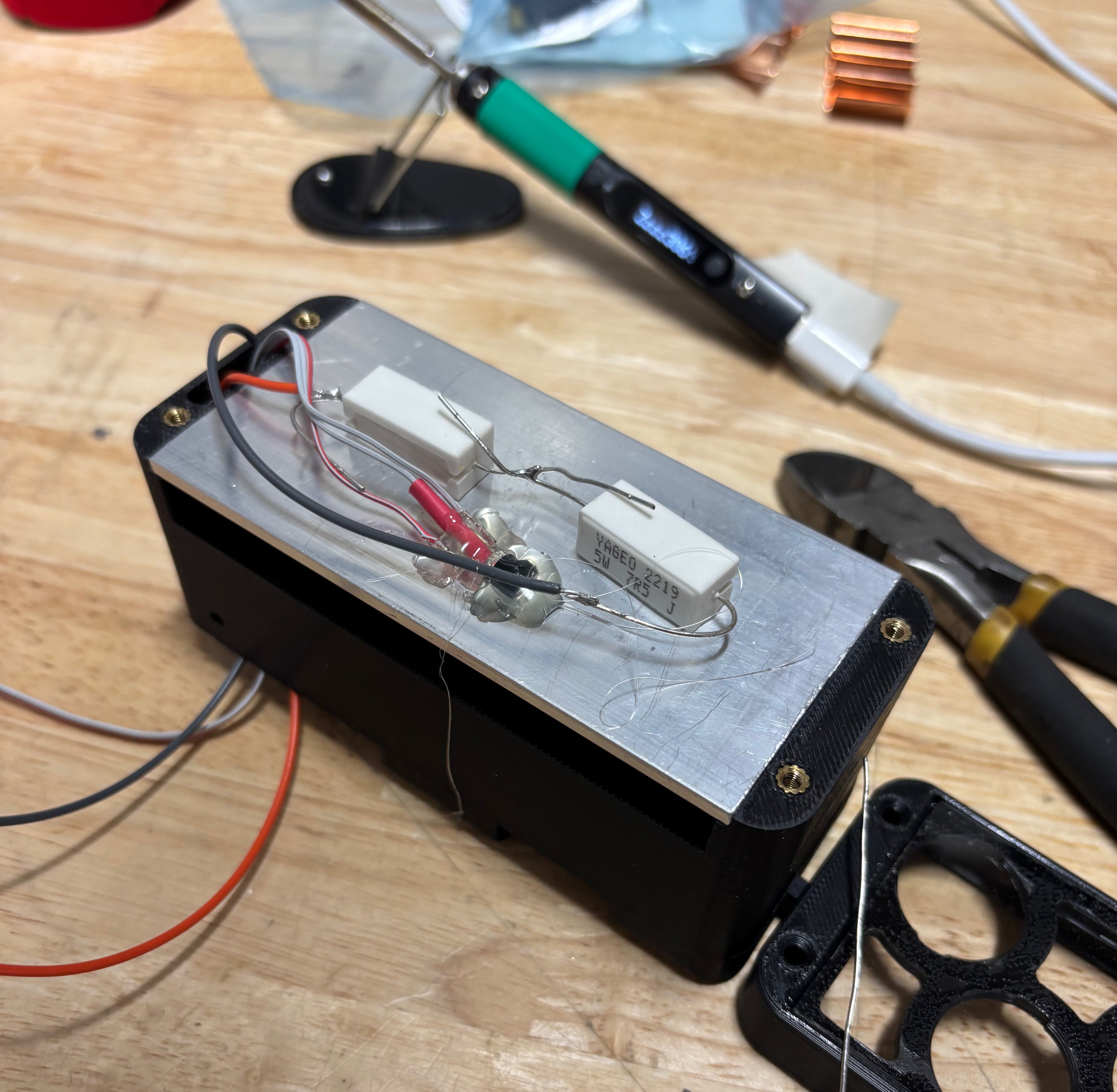
Once I'd turned my copper sheet into a weird cardboard looking thing, it was time to test it. I superglued a couple power resistors and a TMP36 analog temp sensor to the aluminum plate and put it all in a spare enclosure that I had.
![]()
Don't worry, this was just for testing ![]()
The test rig Thermal Resistance Measurement Results
The data was pretty interesting. My number to beat was 5.4K/W, which was the spec'd thermal resistance of the two off-the-shelf heatsinks, and would give me a max LED junction temperature rise of around 120˚ C at 15W dissipated. Somehow, my DIY heatsink ended up measuring almost exactly the same as what I was replacing, at 1/3 the weight!Heatsink type Surface area (cm^2) Measured K/W Aluminum plate, bare 52 9.5 Aluminum plate with copper heatsink 217 5.6 Aluminum plate with copper heatsink
bonded with thermal compound217 5.4
Here's a google sheet with all my test data
There were two surprises here:1. Thermal compound made almost no difference. I guess that either the coupling between the aluminum and copper is so poor that it couldn't be filled, or so good that thermal compound didn't help?
2. The copper reduced the overall thermal resistance by less than half, implying that it has a higher thermal resistance than the bare aluminum plate, despite having more than 3 times the surface area.
I have a few theories to explain the second surprise.
1. A significant amount of heat is radiating out the other side of the aluminum plate and through the front of the light. This would effectively give it more surface area.
2. The thermal contact between the copper and aluminum is really bad. I might try thermal epoxy or adhesive to remedy this.
3. The copper slows down the ambient air currents that keep the aluminum cool.
-
Component Selection
12/16/2025 at 01:07 • 0 commentsMy criteria for this build were:
- Mechanical strength: It's gotta stay in one piece when I land 5 feet short on a tabletop jump and bottom out my suspension hard enough to pop both tires
- Water resistance: PNW winter means muddy water everywhere, both from the sky and from my tires
- Brightness: >1k lumens, ideally closer to 2k from what I've read online
- Battery life: >2 hours on full brightness (I'm rarely descending for this long, but it's good to have a buffer)
- Brightness levels: At least 2; full power for descending and sorta bright for climbing
- Beam pattern: Wide so I can see around corners but with a decent throw for when I'm going fast
- No sharp edges, to minimize danger in a crash
- Easy to install and remove from handlebars
- Easy charging (ideally USB-C)
- Weight: not too heavy I guess
These requirements, and their implications for the mechanical and electrical design, made the project more involved than I initially expected. Not that I'm complaining.
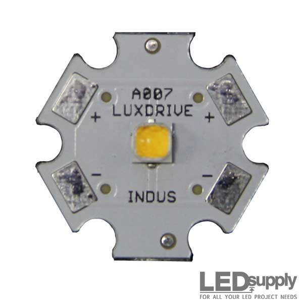
My choice of LED was mostly based on availability. There's plenty of white LEDs out there with tradeoffs between CRI, brightness, thermal resistance, and so on. The Cree XP-L HD is older but still holds up alright, and you can get it mounted on a star MPCB from LEDSupply for a decent price.
![Cree XLamp XP-L High Density LED Star]() For the battery, the choice of 21700 cells was easy. They're mechanically robust and readily available with excellent energy density. Plus, I built a battery for my eBike with this cell format a couple years ago so I already had a spot welder from Maletrics. With the format selected, the Samsung 50S cell was a great choice - 5Ah/18Wh per 70g cell, for around 250Wh/kg!
For the battery, the choice of 21700 cells was easy. They're mechanically robust and readily available with excellent energy density. Plus, I built a battery for my eBike with this cell format a couple years ago so I already had a spot welder from Maletrics. With the format selected, the Samsung 50S cell was a great choice - 5Ah/18Wh per 70g cell, for around 250Wh/kg!
![Samsung 50S 21700 5000mAh 25A Battery]() Doing the math on power, if I want 1500 lumens and assume I can get 100 lumens per watt, that means the LEDs would pull around 15 watts. Add a little extra for loss in the LED driver, and two 18Wh cells should give me right around 2 hours of light.
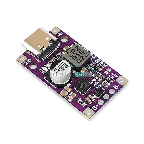
I put the two cells in series because my original design was based around the Sparkfun Picobuck LED driver, which has a minimum input voltage of 6V. The annoying thing about this is that when you have Lithium-Ion cells in series, you should really have a way to keep an eye on the voltage of each cell and make sure they stay balanced. Luckily, I found this cool little charger board that can charge and balance 2 Lithium cells at 15W from USB-C! It's based around the IP2326 chip that handles the USB QC negotiation, voltage conversion, and charge monitoring.
Doing the math on power, if I want 1500 lumens and assume I can get 100 lumens per watt, that means the LEDs would pull around 15 watts. Add a little extra for loss in the LED driver, and two 18Wh cells should give me right around 2 hours of light.
I put the two cells in series because my original design was based around the Sparkfun Picobuck LED driver, which has a minimum input voltage of 6V. The annoying thing about this is that when you have Lithium-Ion cells in series, you should really have a way to keep an eye on the voltage of each cell and make sure they stay balanced. Luckily, I found this cool little charger board that can charge and balance 2 Lithium cells at 15W from USB-C! It's based around the IP2326 chip that handles the USB QC negotiation, voltage conversion, and charge monitoring.
![15W 2S / 3S Type-C Li-ion Battery Charger Module Charging Board QC Fast Charging - Picture 1 of 20]()
 Aluminum Top Mount")