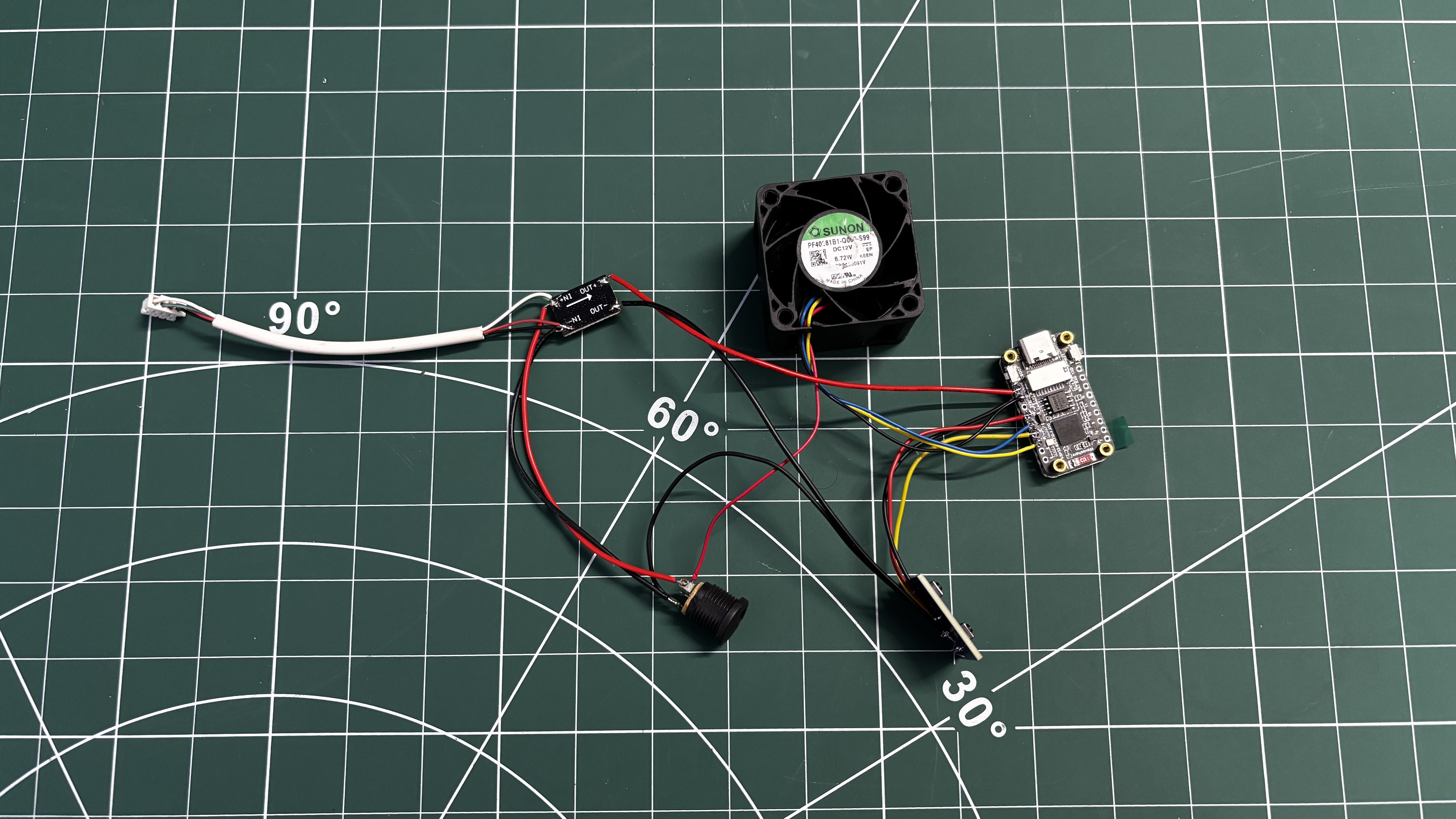
We then moved on to the wiring stage by following the prepared wiring diagram and connecting all components together.
The switch PCB was connected by wiring button A and button B signal lines to GPIO 2 and GPIO 3 of the ESP32-S3 board, with the switch ground connected to the common GND.
Next, the power connections were made. The output side of the DC–DC buck converter was connected to the ESP32-S3 board, with 5 V routed to the VIN pin and GND connected to ground.
On the input side of the buck converter, a barrel DC jack was added to supply the main input voltage.
In addition, a CON4 connector was connected in parallel with the barrel jack’s VCC and GND.
This connector is used to supply 12 V power to the LattePanda Delta using the same external adapter, allowing both the control electronics and the SBC to be powered from a single power source.
2
3D MODEL
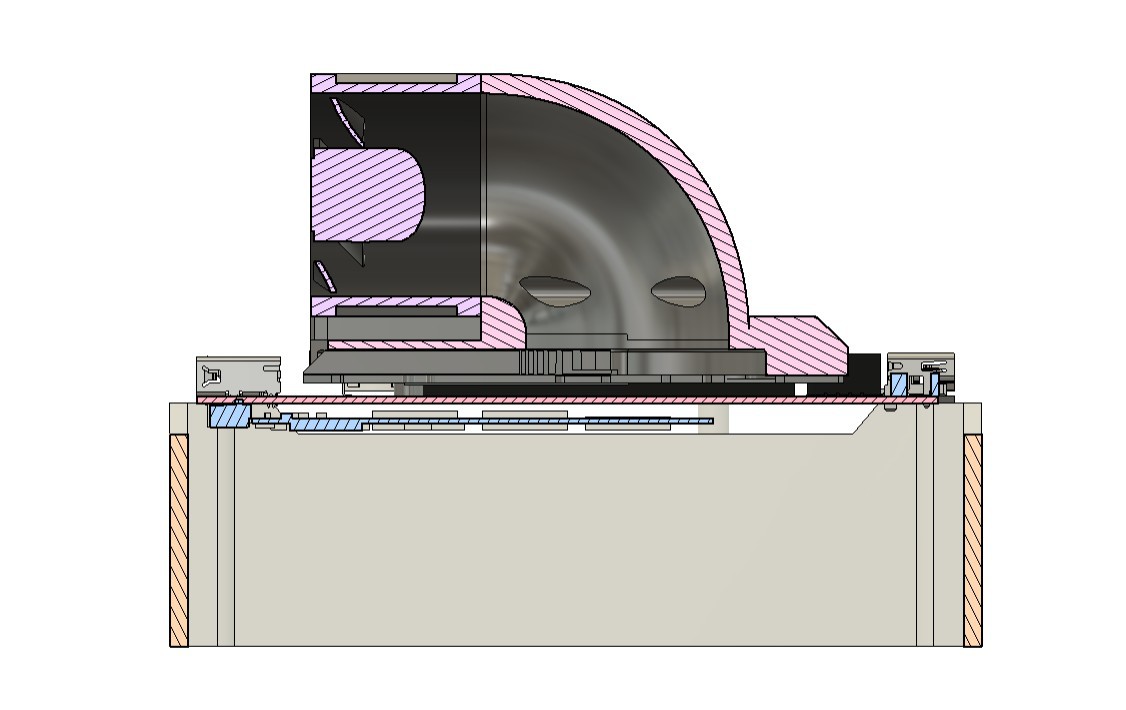
The entire 3D design process was based around the idea of adding a server fan on top of the heatsink. The goal was for the fan to intake air from the front and direct it at high speed onto the heatsink, allowing the air to pass through the fins and maintain a stable operating temperature.
In the stock design, the fan is positioned horizontally inside a pocket in the heatsink and covered by a plastic cover. This cover acts as a duct, with an opening only above the fan blades, allowing the fan to pull air in and force it through the heatsink fins.
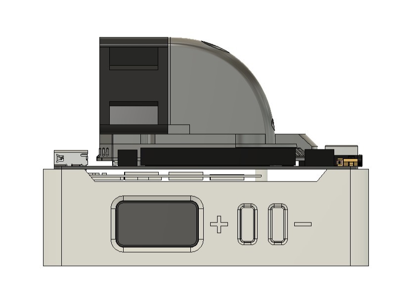
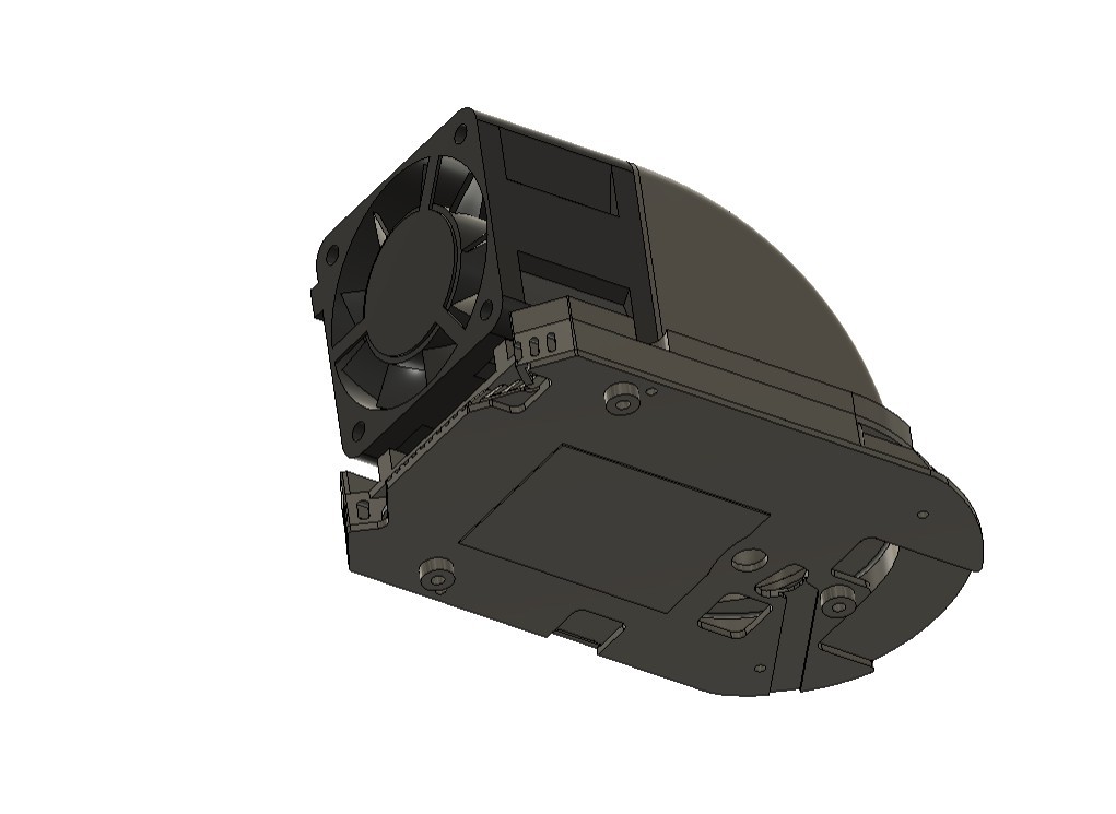
We initially tried to replicate this approach by placing our server fan over the heatsink and creating a cover based on the original heatsink file. This modification allowed us to mount the fan correctly, but it did not provide optimal airflow control. After testing several design iterations, we finalized a solution where the fan is mounted tangentially. In this configuration, the fan draws air from one side and directs it into the heatsink through a custom duct. This duct also acts as a heatsink cover, ensuring that when high-speed air enters the heatsink, the only exit path is through the fins.
All of these modifications were possible because the official 3D models of the LattePanda Delta 3 were available on the DFRobot wiki pages, allowing accurate alignment and mechanical integration.
The next step was to design a base or holder that supports the LattePanda Delta while also housing the ESP32 display, the switch PCB, and dedicated button actuators for operating the push buttons.
After finalizing the design, the duct, LattePanda holder frame, and button actuator components were exported as mesh files and 3D printed using an Anycubic Kobra S1 with white PLA.
3
THREADED INSERT PROCESS
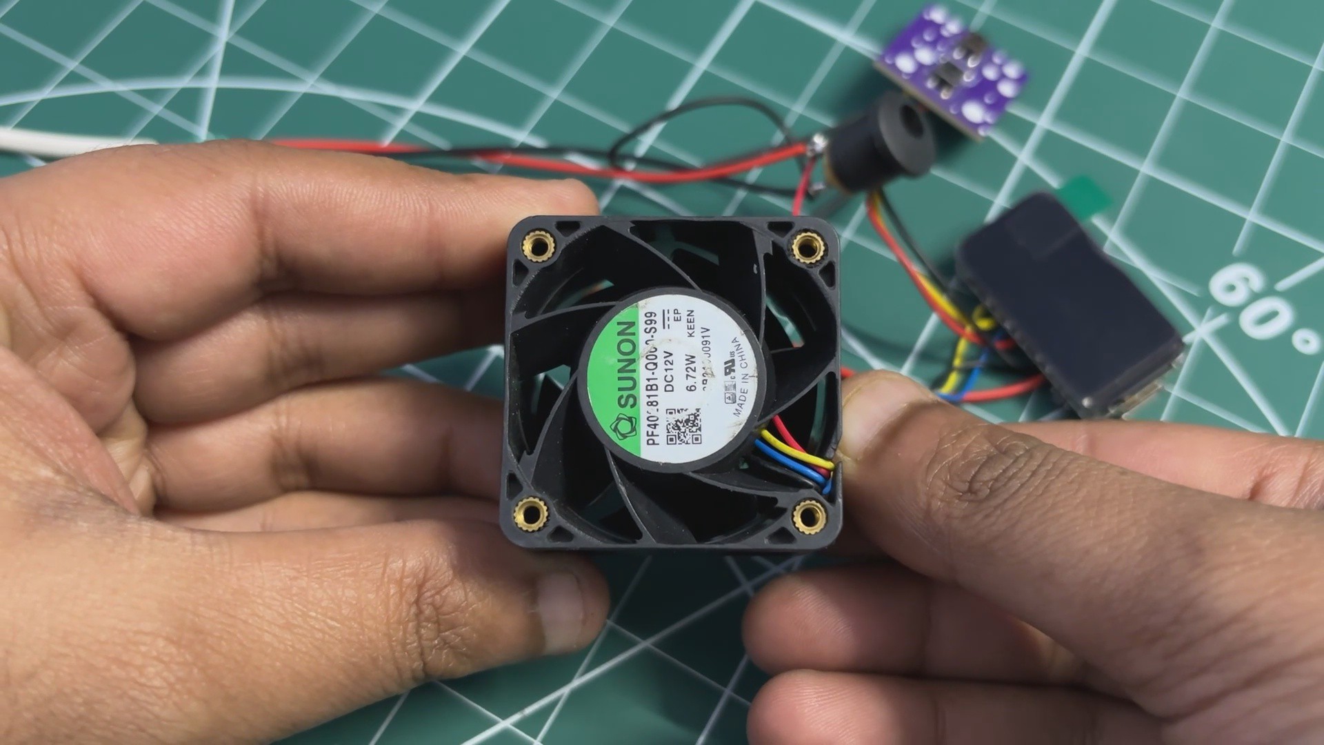
Our original plan was to mount the fan to the duct using M2.5 screws and nuts. However, the DC fan does not have threaded mounting holes.
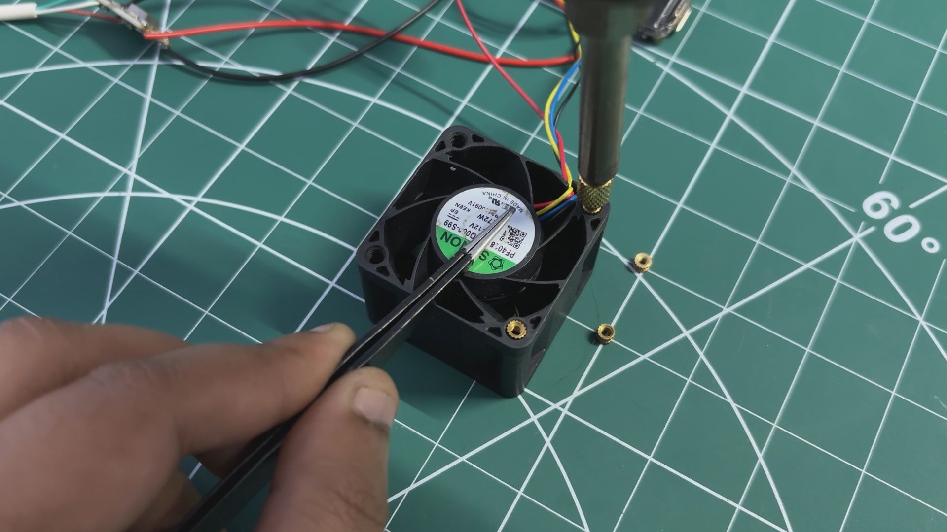
To solve this, we added M2.5 threaded inserts to all four mounting holes of the fan. A soldering iron set to around 250°C was used for this process.
Each threaded insert was carefully placed over a mounting hole and then pressed in using the heated soldering iron tip. The heat softens the plastic around the hole, allowing the insert to sink in smoothly. Once the plastic cools down, the insert locks firmly in place.
By adding threaded inserts to all four mounting points, we created proper, durable threads in the fan body. These threads are then used to securely mount both the BLDC fan and the duct component, resulting in a strong and serviceable mechanical assembly.
4
HEATSINK ASSEMBLY
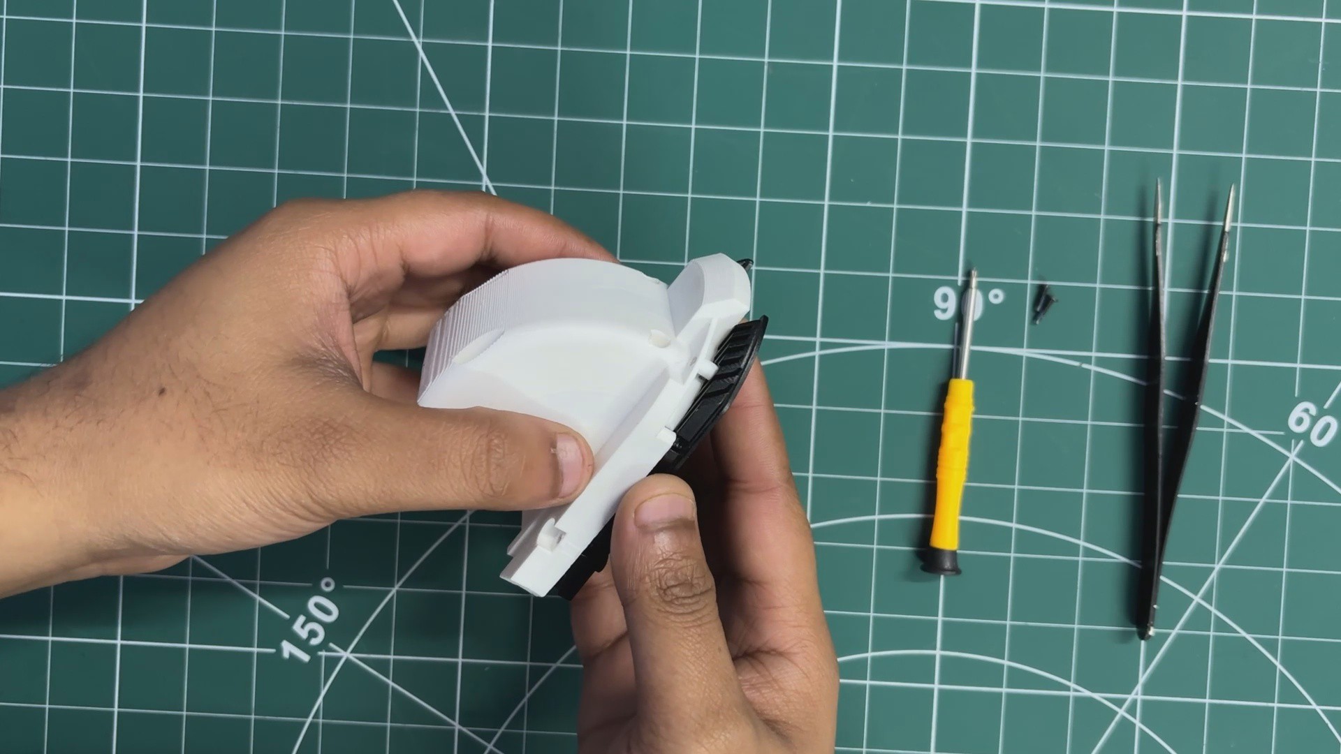
We start the heatsink assembly process by placing the duct part over the aluminum heatsink.
The duct is positioned by aligning the mounting holes of both parts together.
Using M2.5 bolts, we secure the duct firmly to the heatsink.
Next, we apply a sufficient amount of silicone-based thermal grease over the processor die and spread it evenly to ensure proper heat transfer.
The heatsink assembly is then placed over the CPU, carefully aligning the mounting holes of the LattePanda with the screw bosses on the heatsink.
From the bottom side, we fasten the heatsink in place using the mounting screws, completing the heatsink installation.
5
FINAL ASSEMBLY
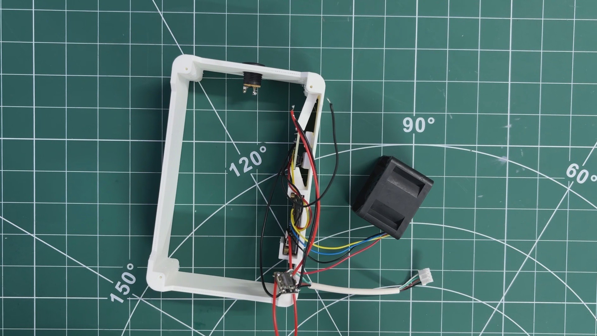
For the final assembly, we first placed the ESP32 display board into its designated position inside the LattePanda holder.
Next, the button actuators were inserted into the slots provided in the holder, followed by installing the switch PCB behind them so that the actuators aligned correctly with the push buttons.
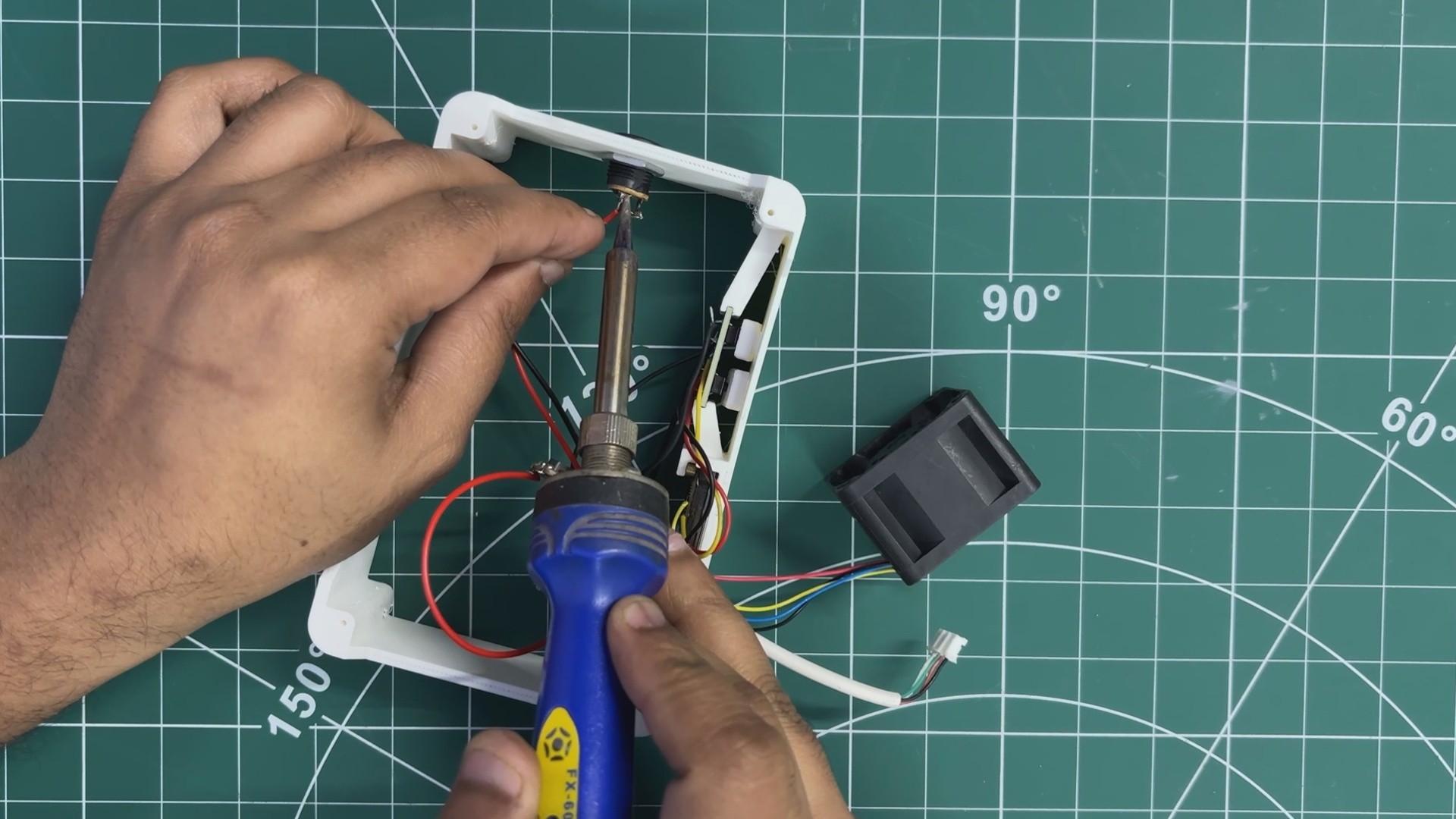
The DC barrel jack was then mounted in its cutout and secured using the included nut. After that, the VCC and GND connections from the input side of the DC–DC buck converter were connected to the DC jack.
The LattePanda Delta was then placed onto its mounting position and secured using four M2 screws.
Finally, the CON4 connector was connected to the LattePanda’s power input, allowing the board to be powered directly from the DC jack.
6
RESULT
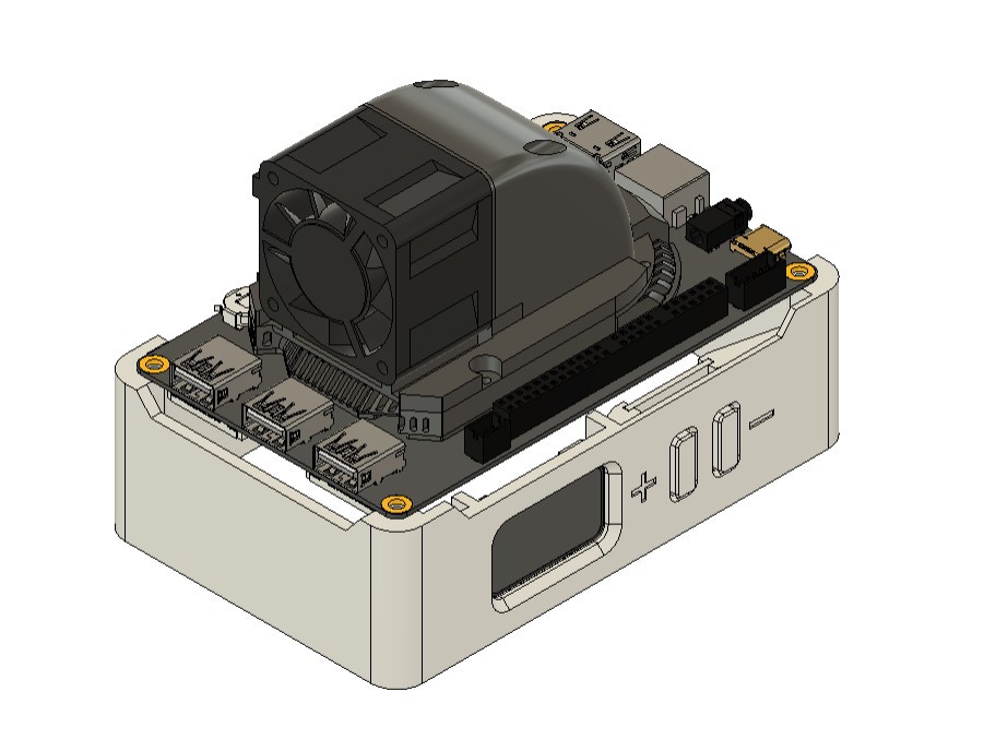
The end result of this build is a LattePanda Delta equipped with a completely custom cooling solution. The system consists of a high-airflow server fan paired with a custom-designed airflow duct, along with a compact stand that houses a display and two control buttons while also serving as a stable holder for the board.
With this setup, the entire cooling section of the LattePanda Delta has been redesigned. Since the new fan provides significantly higher airflow than the original one, the system now has enough thermal headroom to safely handle higher CPU loads and even light overclocking, with the fan and heatsink keeping temperatures under control.
Pressing the plus (+) button moves the device into the first fan mode, and continued presses increase the fan speed at a fixed step rate. The minus (–) button reduces the fan speed in the same manner. The current fan RPM and operating mode are displayed live on the screen, providing immediate feedback.
With this cooling solution in place, the system now idles at around 26–35°C, which is a significant improvement compared to the earlier setup.
Previously, with the stock fan and control circuitry no longer functioning, idle temperatures exceeded 60°C, and the board would shut down under load. This modification restores stability and makes the LattePanda Delta usable again for sustained operation.
7
CONCLUSION
The motivation behind modifying the cooling system of the LattePanda Delta came from another ongoing project. I was working on a game emulator build, with the goal of creating a small, Steam-machine-like device capable of running retro games. The LattePanda Delta 3 is more than powerful enough for this purpose, as demonstrated in my earlier Latteintosh project, so I needed the board to operate at its best for extended periods.
During this process, the stock cooling fan on the board failed. Instead of waiting for a replacement fan module, I decided to take the opportunity to design an externally controlled cooling system. This approach not only solved the immediate cooling problem but also resulted in a more flexible, higher-performance solution that turned out to be both effective—and admittedly loud.
Overall, the project was a success, and all design files, code, and resources related to this build are attached on the project page.
 Arnov Sharma
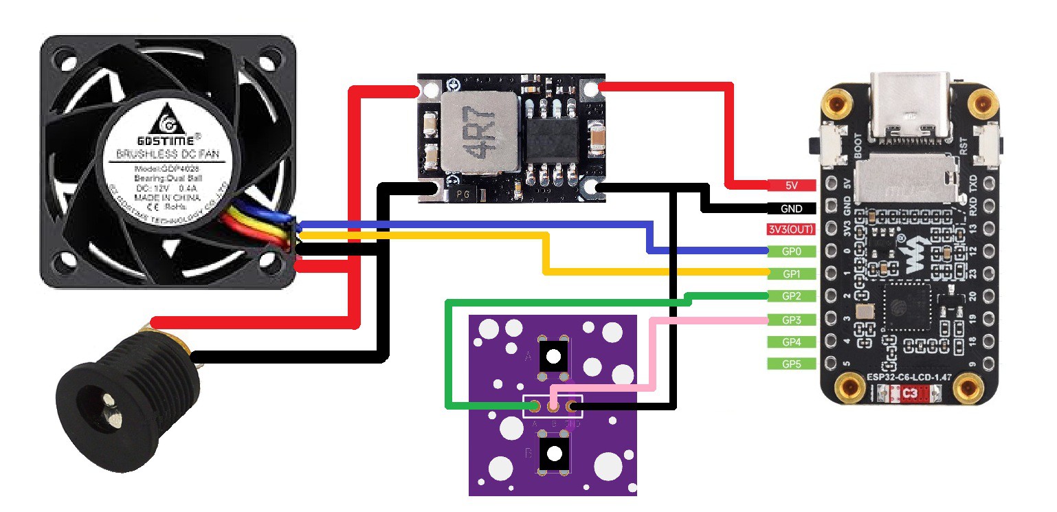


Discussions
Become a Hackaday.io Member
Create an account to leave a comment. Already have an account? Log In.