 Sagar 001
In one of our previous articles, we discussed the constant current and constant voltage profiles in detail. These are the most important for an analog engineer working with a lot of equipment. We have to test the DC supplies a lot, and most of them are batteries of various types. You will find a lot of battery-charging-related stuff in my profile. However, when it comes to performance testing, I must test the battery under a load. Changing the type of load is not always possible; I can use a simple big resistor made for current sensing. However, the fact is that they are not variable, and I am unable to find any high-wattage resistor. That’s how I address the issue and create my own electronic load version 1.0.
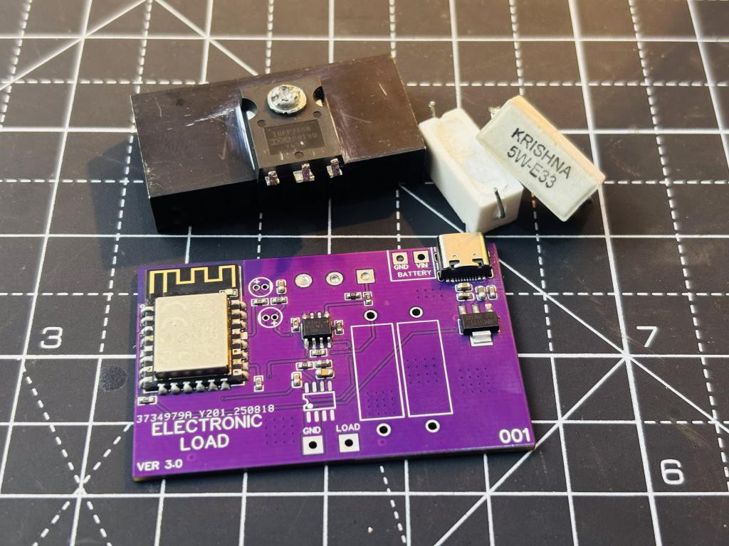
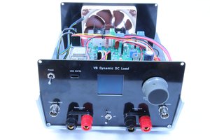
Eload basically acts as a variable resistor, but if I say from my engineering mind, it is a constant current load. Means that whatever the voltage, if we fix the current, it will only draw that constant amount of current. In this way, the name can be CC load. Now, in version 1.0, we can vary this constant current by rotating the potentiometer and set coarse/fine values. But after using it for a month or so, I have addressed some issues. First, I do not need that much wattage, so I reduced the size of the heatsink. I also need digital control and a measuring display. I do not need ultra precision, but it should be easy to monitor the real-time current and wattage. And here is the modified version of our electronic load.
Electronic load V3:
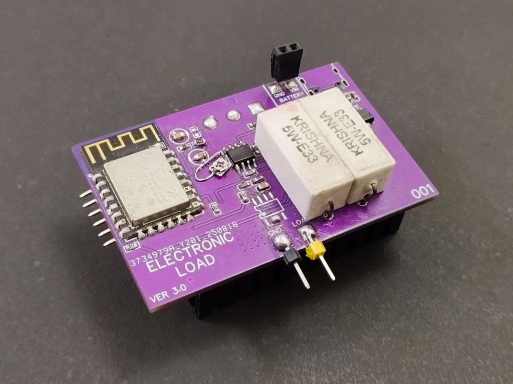
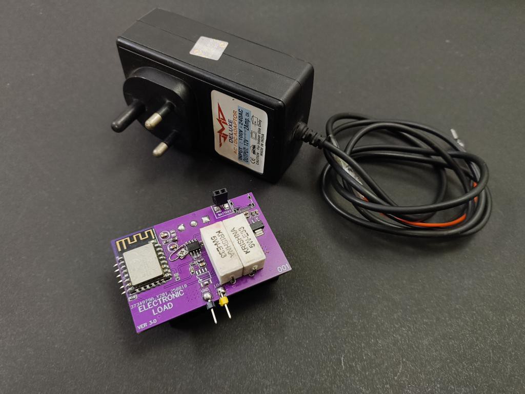
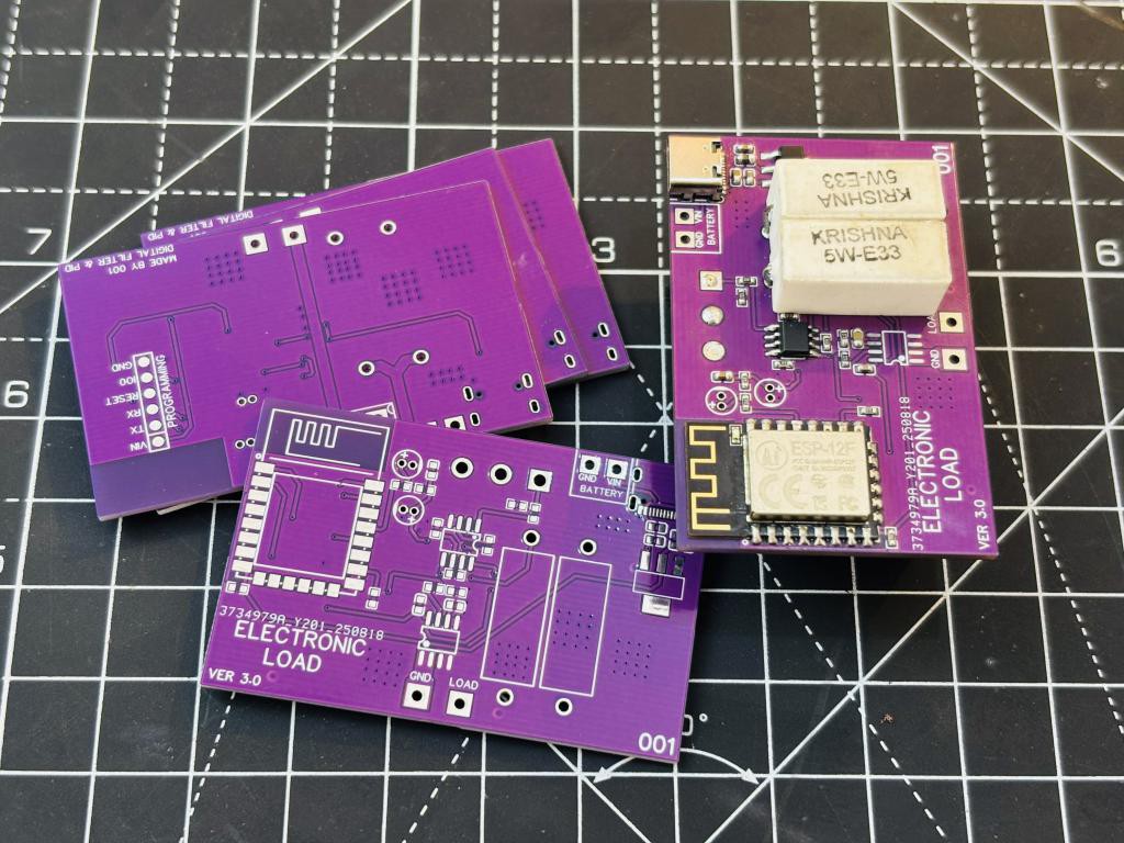
I used a low-value shunt resistor to minimise the drop across it. I have used a PCB mount heatsink on the transistor. To display everything and control this load easily, I have designed a web server and integrated all the current monitoring there. It is still powered by 12V, and an ESP8266 is used for controlling the load. Moreover, I reduced the BOM cost, and after testing, I modified the design slightly; the PCB design is attached below. This can work fine up to 30 watts in continuous current mode, which is more than enough for testing single-cell batteries and USB PD ICs.
The design:
A power MOSFET with a low-value current shunt resistor is used; in this case, 0.165 ohms. This means that if 1A flows through the load, the voltage drop across the shunt resistor is 165 mV. This value goes into an op-amp and is compared to a reference voltage. When both are the same, the load is locked. For example:
vREF: 165mV
Current shunt drop: 165mV
Electronic load is locked to 1A.
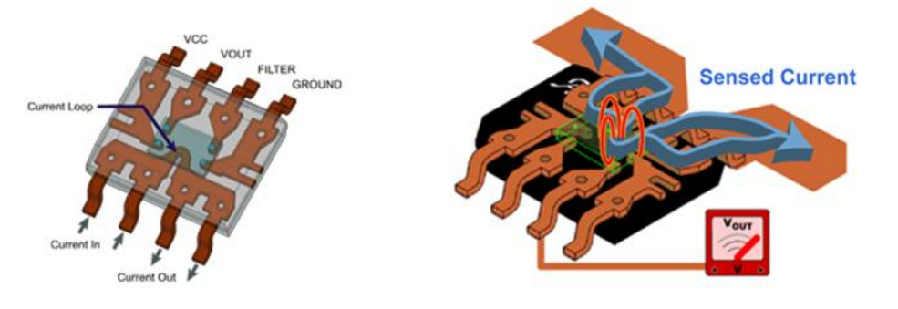
However, 165mV is a very small value, which is why I used an DC amplifier to raise the level by 2-3x. Then it is compared with the reference. The reference voltage is produced by potentiometers in the older design, but for digital control, we used the PWM method here. PWM duty cycle determines the voltage; for more information, please refer to the full details. After this, if we apply any voltage source across the terminals of Eload, it will start loading that supply. To maintain the set value and lock value equal, I have implemented an ACS712 current measurement and used a PID controller to fine-tune the PWM. This feature is currently under testing and will be fully updated within a week or so.
Components required:
- ESP8266 12e Wi-Fi MCU
- IRFP260N N-channel MOSFET
- LM358 Operational amplifier
- ACS712 hall effect sensor
- 10K SMD potentiometer
- Decoupling capacitor 100n and 1uf
- 10K, 4.7 K, and 1K resistors
- 0.33Ohm 5W resistor (or 0.165ohms)
- 12V adapter
- PCB from NEXTPCB
Circuit Description:
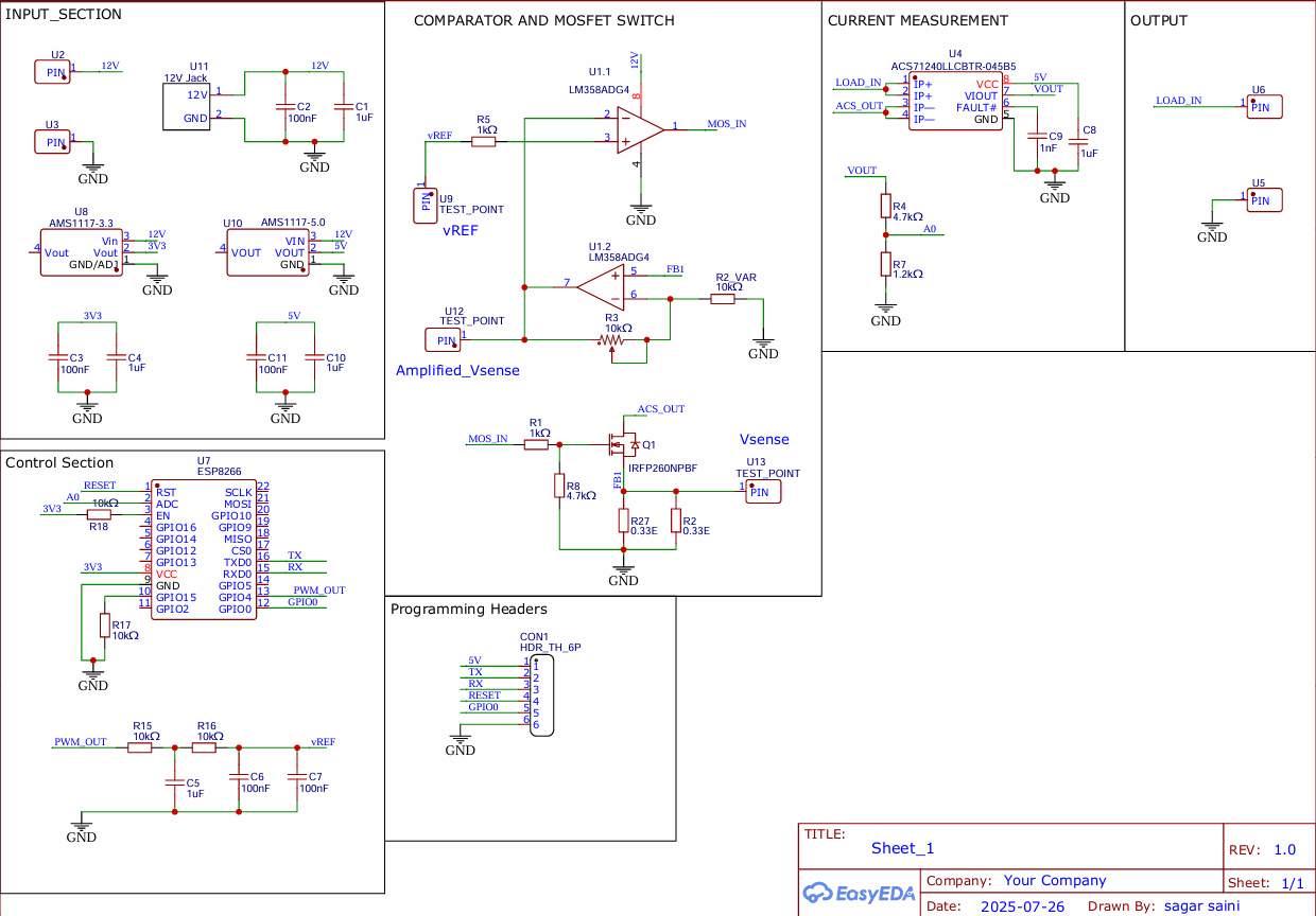
So, I have made the circuit in different sections, with the input on the left top and the outputs on the right side. The input section contains a USB-C input, which is later charged with a 12V DC jack, and some decoupling capacitors for the LDO AMS1117 3.3V. The second section consists of the MOSFET and control block, where the comparator serves as the MOSFET driver, and the MOSFET is connected in parallel with two 0.33 ohm resistors.
The third section is the PID feedback and current sensing section,...
Read more »
 Bharbour
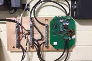
 Bud Bennett