Close
0%
0%

WEEDINATOR 2026 Agricultural Robot

After 7 years, the project is still very much alive!

Similar projects worth following
The WEEDINATOR project is focused on building a small robot to perform tasks in the agricultural realm. The hardware for the control system and the safety cameras modules is open source.

What is the WEEDINATOR?

The WEEDINATOR is a collection of modules to enable autonomous weeding of rows of vegetables by a robot tractor. It is not limited to weeding and can be adapted for planting and other functions.

What are the main components of the WEEDINATOR?

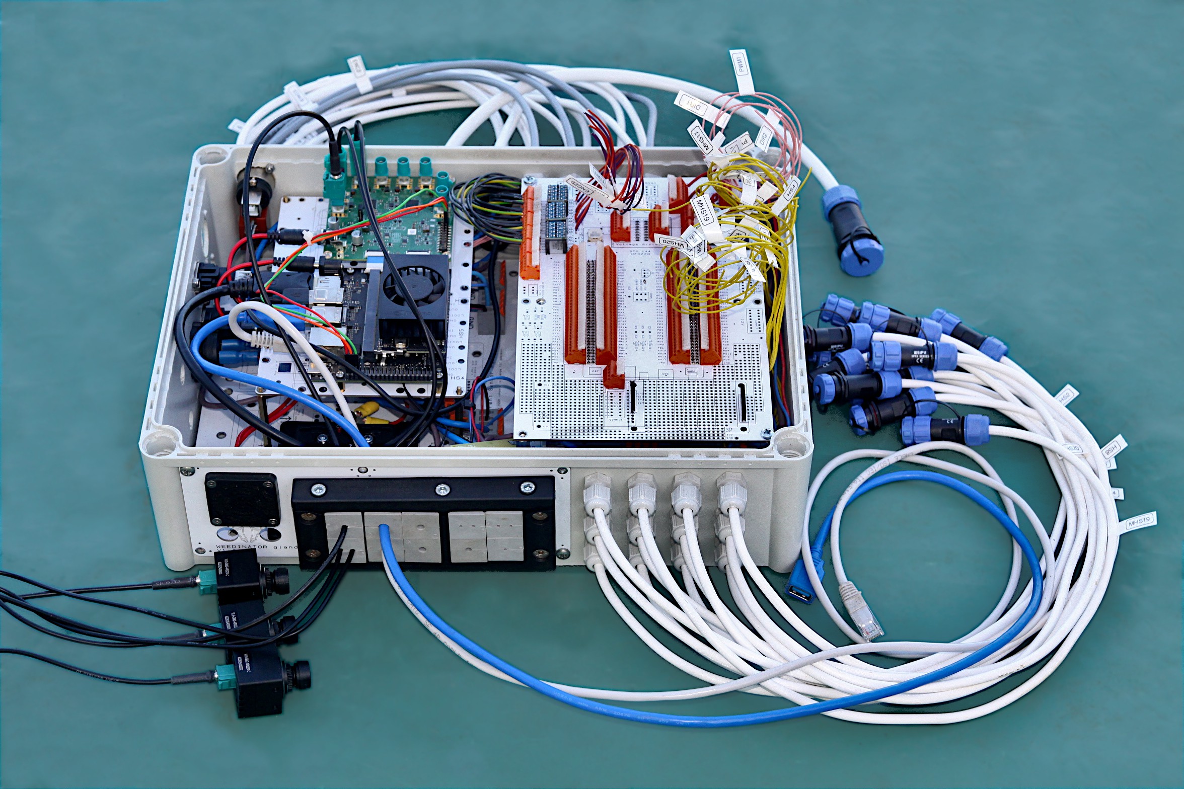
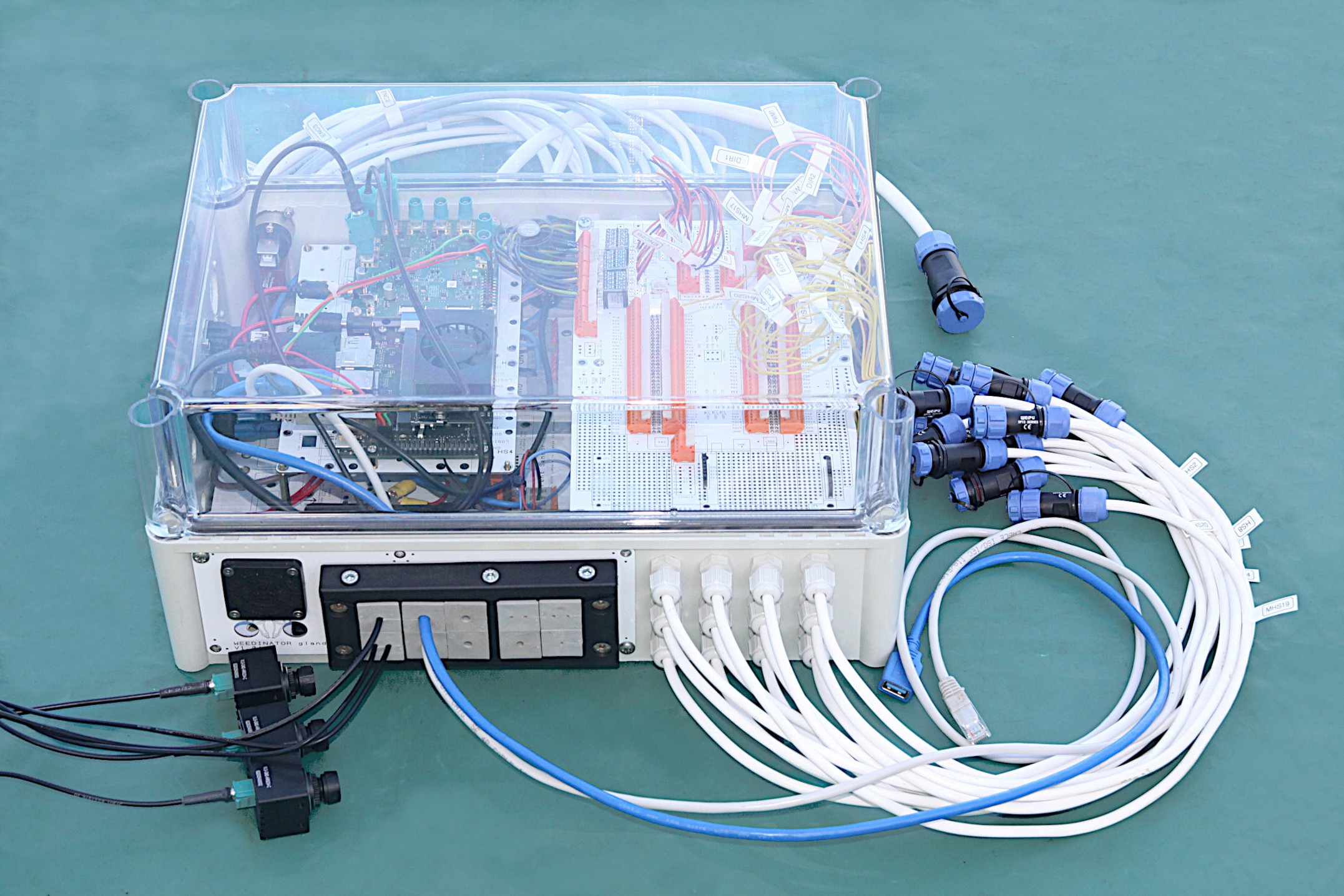
We call the 3 primary control modules Control Box 1, Control Box 2 and Safety Cameras. Box 1 is an infinitely hackable hardware system with a high end STM MCU, a set of automotive relays and automotive grade high side switches. Other sub modules in Box 1 include motor controllers and a 10 way fuse box. Box 2 can be configured in a similar way to Box 1 but would normally include a small board computer (SBC) for communication via 4G and crop detection with cameras and machine learning. WEEDINATOR Safety Cameras is a module for detecting the presence of people and a robot would normally have at least one at the front and back.

There is also a hydraulically powered cultivating (weeding) implement for towing behind the tractor.

More info to follow - watch this space!


Sponsored by PCBWay - the best quality and most reliable: https://www.pcbway.com/ . Other manufacturers exist, but we had quality issues with some of  them.

Apart from the primary control system we are working on the cultivating implement, which has an Ai camera attached that scans the grids of crops as in the video below:

This video shows how we've combined traditional, CPU intensive, Open CV type computer vision systems with modern YOLO26n Ai image inference to try and recognise, and predict, the position of grids of seedlings. The idea is to try and predict when there is a gap between the crops to momentarily stop the cultivator implement in the Y axis and quickly send a set of hydraulically driven rotating claws across the X axis, and back again. The red horizontal X axis line acts as a trigger point and when the system detects that a weighted combination of the inferred Ai driven grid center and the traditional CV grid center overlap, or are close enough to one another, a data point is added to the data array. The system is able to detect the next grid center which is useful if the system misses a trigger point. It's not perfect yet and you can see it does actually miss one prediction, but as long as it gets most of them, this should be ok.

  • Crop Grid Detection

    GOAT INDUSTRIES4 days ago 0 comments

    Apart from the primary control system we are working on the cultivating implement, which has an Ai camera attached that scans the grids of crops as in the video below:

    This video shows how we've combined traditional, CPU intensive, Open CV type computer vision systems with modern YOLO26n Ai image inference to try and recognise, and predict, the position of grids of seedlings. The idea is to try and predict when there is a gap between the crops to momentarily stop the cultivator implement in the Y axis and quickly send a set of hydraulically driven rotating claws across the X axis, and back again. The red horizontal X axis line acts as a trigger point and when the system detects that a weighted combination of the inferred Ai driven grid center and the traditional CV grid center overlap, or are close enough to one another, a data point is added to the data array. The system is able to detect the next grid center which is useful if the system misses a trigger point. It's not perfect yet and you can see it does actually miss one prediction, but as long as it gets most of them, this should be ok.

View project log

  • 1
    WEEDINATOR Ai Camera Control Box (Box 2)

    Weedinator Camera & Control Box Components

    • Enclosure & Mounting
    • Glands & Seals
      • Split Glands: Icotek KEL-ULTRA flex Large Split Glands for connectorized cables
      • M12 Glands: IP68 M12 Polyamide Cable Gland (Light Grey)
      • M16 Glands: IP68 M16 Polyamide Cable Gland (Light Grey)
    • Cooling & Environment
      • Vent Gland: IP66 Air Vent Gland, M12 x 1.5 (Prevents condensation)
    • Power Distribution
    • Voltage Regulation (On-Board)
      • 5V Regulator: D2-Pack 5V Voltage Regulator (LM2576 or similar)
      • 3.3V Regulator: D2-Pack 3.3V Voltage Regulator
    • Motor Control
      • Motor Driver: Cytron 10A Dual Channel Motor Driver (MDD10A)
    • Computing & High-End Vision
      • Jetson Nano: NVIDIA Jetson Nano Developer Kit
      • Vision Interface: VL-GM2-8CAM-RPI22 (GMSL2 8-Camera Hub for RPi/Jetson)
      • Camera Units: VLS-GM2-AR0234-C-S83-IR (Global Shutter GMSL2 Cameras)
        • Supplier: VizionCam
      • Coax Cables: Vizionlink-COAX1-Cable (0300 and 0500 lengths)
        • Supplier: VizionCam
    • Navigation & Logic
      • GNSS Receiver: SparkFun GPS-RTK2 Board - ZED-F9P (Qwiic)
      • Level Shifter: SparkFun 4-Channel Logic Level Converter
    • Connectivity & Fabrication

    Step by step video instructions on how to assemble the components onto the WEEDINATOR MCU PCB.

    This guide covers the assembly process for the WEEDINATOR MCU PCB, moving from precision surface-mount work to robust through-hole connectors.

    SMD Population and Stenciling

    The assembly begins with the surface-mount device (SMD) components. Precision at this stage prevents logic errors later.

    • Voltage Regulators: Install the 5V and 3.3V D2-pack regulators in the top-left corner.
    Note: Ensure the 3.3V component is the correct variant; several D2-pack components look identical but have different pinouts.
    • Stenciling: Use a microscope to align the stencil perfectly.
    • Maintenance: Clean the stencil immediately after use with isopropyl alcohol. If solder paste hardens in the fine apertures, it is nearly impossible to remove.
    • PCB Quality: High-quality fabrication (like PCBWay) is recommended. Lower-tier boards may have defects, such as pins pre-filled with solder, which complicate assembly.

    Component Identification & Reflow

    Before heating the board in the reflow oven, double-check component values and polarities.

    • Resistors (0603): Distinguish between 10k and 1k resistors. The 1k resistors typically have a "0" marking, while 10k resistors require a microscope to read the code.
    • LEDs & Buzzer: * LED Cathode: Look for the tiny green mark on the LED to identify the cathode.
      • Buzzer: Match the orientation of the writing on the buzzer to the silk-screen on the PCB.
    • Capacitors: Install the black crescent capacitors to stabilize the voltage supply.
    • Regulator Pins: On D2-pack regulators, the middle pin may not touch the PCB pad. This is acceptable as the large ground tab at the back provides the primary electrical and thermal connection.

    Through-Hole Components & Headers

    Once the SMD work is reflowed, move to through-hole soldering.

    • SBUS Inverter: Solder the ZX450 NPN transistor. The PCB graphics clearly indicate the flat-side orientation.
    • MCU Headers: 1. Tack-solder only the end pins first. 2. Slide the MCU onto the headers to check alignment. 3. Warning: Never force the MCU onto wonky headers; this can crack the silicon chip. If the headers are out of alignment, reheat the end pins and adjust until the MCU "clicks" into place easily.

    MCU Fitting & WAGO Connectors

    • Installation Hack: Use a small amount of WD-40 on the header pins. It significantly reduces the friction required to seat or remove the MCU.
    • Safe Removal: When prying the MCU off, use a screwdriver gingerly to avoid "banana-shaping" (bending) the PCB.
    • Terminal Blocks: This board uses orange WAGO-style spring connectors rather than traditional screw terminals.
      • They are more reliable under vibration.
      • Like the headers, solder only the ends first to ensure they are seated flush against the PCB before finishing the remaining pins.

    Final Setup and Commissioning

    • Grounding: Solder all available ground connectors—the more ground paths, the better the signal integrity.
    • GPS Support: Install headers for the daughterboard, which supports dual Ublox Series 9 units for precise heading data.
    • Hardware Jumpers: You must remove jumpers SB57 and SB31. This disables the Ethernet pins to free up PA1 and PA7 for system use.
    • The "Smoke Test":
      1. Check the 5V and 3.3V rails with a multimeter.
      2. Power the board with preloaded test code. A successful build will trigger an audible beep from the buzzer and a flash from the LEDs.

    Populating the 20 Channel High-side Switch PCB

    PCB Design and Enclosure Logistics

    • PCB Color Choice: For this project, white PCBs were specifically chosen over black. In a closed enclosure, white surfaces reflect ambient light, making it much easier to see the wiring and components during maintenance.
    • High-Side Switches vs. Relays: * High-Side Switches: These are used for components like flashing beacons and hydraulic solenoid valves.
      • Automotive Relays: Used for higher-current loads (up to 40A) such as engine glow plugs and starter motors.

    Solder Paste Application & Stenciling

    Using a stainless steel stencil is the most efficient way to populate this board, especially given the "massive" footprint of the high-side switch components compared to standard surface-mount parts.

    • Solder Paste Freshness: Ideally, solder paste should be less than six months old. While these large components are more forgiving, fresh paste is essential if your board includes smaller 0603 components.
    • Stencil Technique: 1. Secure the PCB and align the stencil. 2. Apply the paste with a squeegee, ensuring every aperture is filled to the top. 3. Critical Step: Lift the stencil vertically and carefully. Sliding it will smear the paste and cause solder bridges (shorts).
    • Maintenance: Always clean the stencil with isopropyl alcohol immediately after use to prevent paste from hardening in the apertures.

    Reflow Soldering and Manual Rework

    The size of this PCB was maximized to fit the reflow oven, which presents some thermal challenges at the board's perimeter.

    • Edge Component Inspection: Reflow ovens often have "cold spots" near the edges. Components in the center of the board usually come out shiny and well-soldered, while those near the edges may not reach full liquidus temperature.
    • Heavy-Duty Rework: To fix incomplete solder joints on the large component tabs, a high-wattage soldering iron (e.g., 450W) is used.
      • The massive tip stores enough thermal mass to heat the large copper tabs quickly.
      • Heat the tab until the solder becomes "runny" and flows through the joint for a solid mechanical and electrical connection.

    Final Finishing and Connectivity

    • Post-Solder Cleaning: Scrub the board with isopropyl alcohol and a wire brush. This removes flux residue and dislodges any "solder balls" or tiny blobs that could cause a short circuit.
    • Quality Control: Every joint is tested with a continuity meter to ensure there are no errors before the board is powered.
    • Connectors: The final step involves installing WAGO spring connectors. These are preferred over screw terminals for their reliability in high-vibration environments (like a robot or tractor).

    uses on the physical layout and enclosure preparation, ensuring that all sub-assemblies fit within the footprint while maintaining signal integrity and accessibility.

    Enclosure Layout and Component Placement

    The current prototype assembly (Box Two) includes the 20-channel high-side switch PCB, the MCU board, a fuse box with LED fuses, the Jetson Nano, and the camera de-serializer board.

    Key Layout Considerations:

    • Space Constraints: Because this unit (Box Two) is designed to sit flush against "Box One" on the robot, one end of the enclosure must remain completely blank. No components or connectors can protrude from that side.
    • Thermal Management: Cooling fans are positioned in opposite corners to create cross-flow.
    • EMI Interference: It is crucial to keep the cooling fan away from the MCU. Fans can cause signal degradation and electromagnetic interference (EMI) if they are too close to sensitive logic circuits.

    Cable Entry and Gland Strategy

    I am using a modular panel system to organize external connections. This allows for a clean, organized entry point for various wire gauges.

    • Gland Sizes: I’m primarily using 12 mm glands for standard wiring (supporting up to 12 holes in a tight but functional cluster) and 16 mm glands for larger cables.
    • Split Gland System: For USB and camera cables, I’m using "tech glands" (split glands). These are essential for FAKRA connectors found on the cameras; since these connectors are permanent, they cannot be threaded through standard holes. The split gland allows the cable to be slotted in and then sealed.
    • XLR Fittings: I’m using XLR-style housings for the Jetson's DisplayPort and USB ports. While handy for temporary monitoring, they are more prone to shaking loose than fixed glands, so they are reserved for non-critical or temporary connections.

    User Interface and Monitoring

    The exterior of the box features several "quality of life" components for field operations:

    • Voltmeter: Provides an immediate visual check that the alternator is charging and the battery is at the correct voltage.
    • Momentary Switches: Useful for triggering specific software routines or safely shutting down the Jetson/single-board computer.
    • DisplayPort: Externally accessible for monitoring the Jetson's output during debugging without opening the weather-sealed box.

    Next Steps: Enclosure Fabrication

    Now that the internal mapping is complete and the clearances are verified, the next step is to disassemble the boards and begin the drilling process.

    • Tools: I’ll be using hole saws to create the entries for the glands and XLR fittings based on the marked-out patterns.
    • Orientation: Most cables will be routed toward the end of the enclosure that faces the hydraulic solenoid valves on the robot.

    Project Progress: Wiring and Housing Preparation

    Drilling and Enclosure Strategy

    I have finished drilling all the necessary holes in the enclosure. I’ve intentionally drilled about 50% more holes than currently required. In my experience, trying to go back inside the system to rewire or add features later is an absolute nightmare, so having those spares ready is critical.

    I’ve included a large slot for icote split glands. These are great for Ethernet and USB cables because they allow you to pass cables through without having to remove the connectors or couplings. Speaking of connectors, I’ve learned the hard way never to mount the connectors directly into the enclosure holes; it's much better to use a system where the couplings stay outside the box.

    Critical Technical Note: Brass Inserts

    If you are using brass inserts (specifically the type from RS Online), the drill size is absolutely critical.

    • Required Drill Bit: 5.7 mm
    • Warning: If you use a smaller bit, such as 5.5 mm, the screw will lock into the insert during installation, and you will never get it out again.

    Component Assembly and Labeling

    I am now ready to assemble the internal components. The fuse box can stay on, and I’ll be using standoffs for the rest of the parts.

    I’m currently installing a 20-channel high-side switchboard. I have already wired the eight channels on the lower PCB. Proper labeling is essential here; every logic cable and board position is labeled (e.g., "Relay 1," "Relay 2"). Without these labels, it would be impossible to keep track of the system.

    Current Status and Next Steps

    The total channel count is now at 28. The system is expandable; I could stack another PCB to add another 20 channels if needed, though I haven't reached that requirement yet.

    The logic cables are tucked in and routed to one side to keep the layout tidy. I am going to finish connecting the remaining wires and fasten the board down before moving on to the next phase.

    PCB Layer Cake: Assembly and Cable Management

    Layer 1: Switchboard and Power Supply

    The board is currently partially wired with eight channels completed and twelve remaining. I have meticulously labeled everything to ensure clarity during assembly.

    Cable Routing Strategy:

    • Rear Routing: All wires are tucked neatly behind the board rather than across the top.
    • Hinge Accessibility: By keeping the top clear, the board can "hinge" upward if you ever need to access components underneath (like replacing relays) without disconnecting the entire system.
    • Power: The 12V supply comes from the fuse box through a general-purpose connector. While some pins are currently unused, they are ready for future expansion.

    Layer 2: Logic and MCU Integration

    We are now moving into the "layer cake" phase of the build. The logic cables are wired up on one side—I’ve given them a "tug test" to ensure they are secure.

    Cable Sizing and Loads: The wire gauge is strictly chosen based on the current load:

    • 0.75 mm²: Used for the remote connector (low current for hydraulic solenoids and warning beacons).
    • 1.5 mm²: Used where cables double up.
    • 2.5 mm²: Used for groups of four connectors and the main common lines routing back to the base.

    Enclosure Constraints and Flexibility

    Space is becoming tight on two sides of the enclosure because this unit butts up directly against "Control Box 1." Consequently, I’ve had to leave eight channels unwired for now, though they remain available for immediate use if needed.

    Split Gland System: I am using a flexible rubber grommet/split gland system for the network and camera cables.

    • No Cutting Required: This system allows you to pass fat camera cables through the enclosure without cutting the connectors off.
    • Scalability: Each grommet can potentially hold two wires, doubling the capacity of a standard 10-way entry.
    • Dedicated Ports: I’ve reserved four glands specifically for the encoder wires and motor controllers coming off the main MCU board.

    Next Steps

    The MCU board is ready to be bolted down onto the standoffs. Once secured, I will begin routing the long logic cables to their respective terminals on the far side of the enclosure.

    Power and Motor Control

    We’ve made significant progress on the motor wiring and power monitoring:

    1. Wiring Gauges: The motors are wired with 1.5 mm cables, supported by a 2.5 mm main feed to the master switch.
    2. Voltage Monitoring: I’ve installed a handy voltage meter. This is vital for monitoring the health of the battery and confirming the alternator is outputting its expected 14.8V.
    3. Motor Control: The PWM and direction connections use pink color-coded cables routed under the board. These control a dual-channel motor controller, which currently operates a prototype pan-tilt mechanism for our safety cameras.
    4. Motor Polarity: The motor cables are twin-core; if the direction is reversed, simply swapping the connections will fix it.

    Jetson Nano & Vision System

    This box serves as the hub for our vision and processing via the Jetson Nano.

    1. FAKRA Vision System: We are using TechNexion FAKRA cameras rather than standard Raspberry Pi cameras.
    2. Durability: They are waterproof and support long cable runs (up to 15m).
    3. Configuration: We have three connections—one for the front safety camera, one for the rear, and one dedicated to crop detection on the cultivating machine.
    4. Performance: Currently achieving approximately 15 FPS per camera.
    5. Connectivity: * A DisplayPort cable is routed to the exterior for screen communication.
    6. Spare USB ports are available for a wireless keyboard/mouse.
    7. An icote split gland system is used for all USB, Ethernet, and camera cables to avoid cutting connectors and maintain waterproof integrity.

    MCU Communications and Logic

    The Jetson Nano acts as the "Master," communicating via USB (the blue cable) to the local MCU and the MCU in Box One.

    1. Logic Level Shifting: Since the encoders operate at 5V and our system runs at 3.3V, I’ve integrated logic level shifters.
    2. Timer-Based Pins: The MCU is very specific about which pins it uses for encoders and PWM because they are timer-based. We have identified three encoder-compatible pins and are auditing the manual to find more.

    Final Weatherproofing

    To wrap up the hardware side:

    1. The de-serializer board is confirmed to be 14.8V tolerant, making it safe for direct alternator power.
    2. I am installing blanking grommets in all unused holes. This is a small but critical step to keep insects and debris out of the enclosure, which could otherwise cause shorts as they grow or nest.

    MCU Configuration and Pin Mapping

    Encoder and PWM Trade-offs

    I’ve integrated four-core cables for the encoder channels. While an initial LLM analysis of the datasheet suggested a theoretical maximum of 10 encoders and 4 PWM outputs, there is a clear trade-off between these functions. Through experimental verification, I’m aiming for a balanced configuration—likely 8 encoders and 6 PWM outputs.

    The system currently uses logic level converters to handle 5V encoders. Note that 12V encoders would require custom wiring in the provided "hackable space" on the board.

    Current Pin Assignments: | Function | Component | Pins | | :--- | :--- | :--- | | Encoder 1 | Input | PA0, PA1 | | Encoder 2 | Input | PE9, PE11 | | Encoder 3 | Input | PD12, PD13 | | Encoder 4 | Input | Testing in progress | | PWM | Speed Control | PE4, PA5, PC7 |

    Modular Hardware Adaptations

    The beauty of this system is its modularity. Although this is "Box Two" (the Camera Box), it can be adapted depending on the rig requirements:

    1. Motor Controllers: Currently, I only have one dual-channel controller for the pan-tilt cameras. However, there is room to bolt on 3 to 4 single-channel controllers if needed.
    2. GPS Integration: While this box doesn't use it, the board is designed to support a bolt-on GPS system.
    3. Stacking: There is potential to raise the PCBs using standoffs to insert additional layers, such as extra motor controller boards, above or below the current stack.

    Physical Clearances and Enclosure Fit

    With the lid on, the FAKRA camera cables present a height restriction. They exit the de-serializer board vertically, meaning the Jetson/Nano PCB stack cannot be raised much higher without putting stress on the connectors or requiring a sharp bend in the cables.

    I estimate there’s about 30mm of vertical play available, which might just be enough for one extra layer of motor control if I’m careful with the routing.

    The Full Rig Setup

    In the final configuration, this Camera Box (Box Two) will sit alongside Box One. Box One is identical in size but omits the Jetson and de-serializer board to provide maximum real estate for heavy-duty motor controllers and the primary GPS system.

  • 2
    Step 2

View all instructions

Enjoy this project?

Share

Discussions

Does this project spark your interest?

Become a member to follow this project and never miss any updates