 Rhea Rae
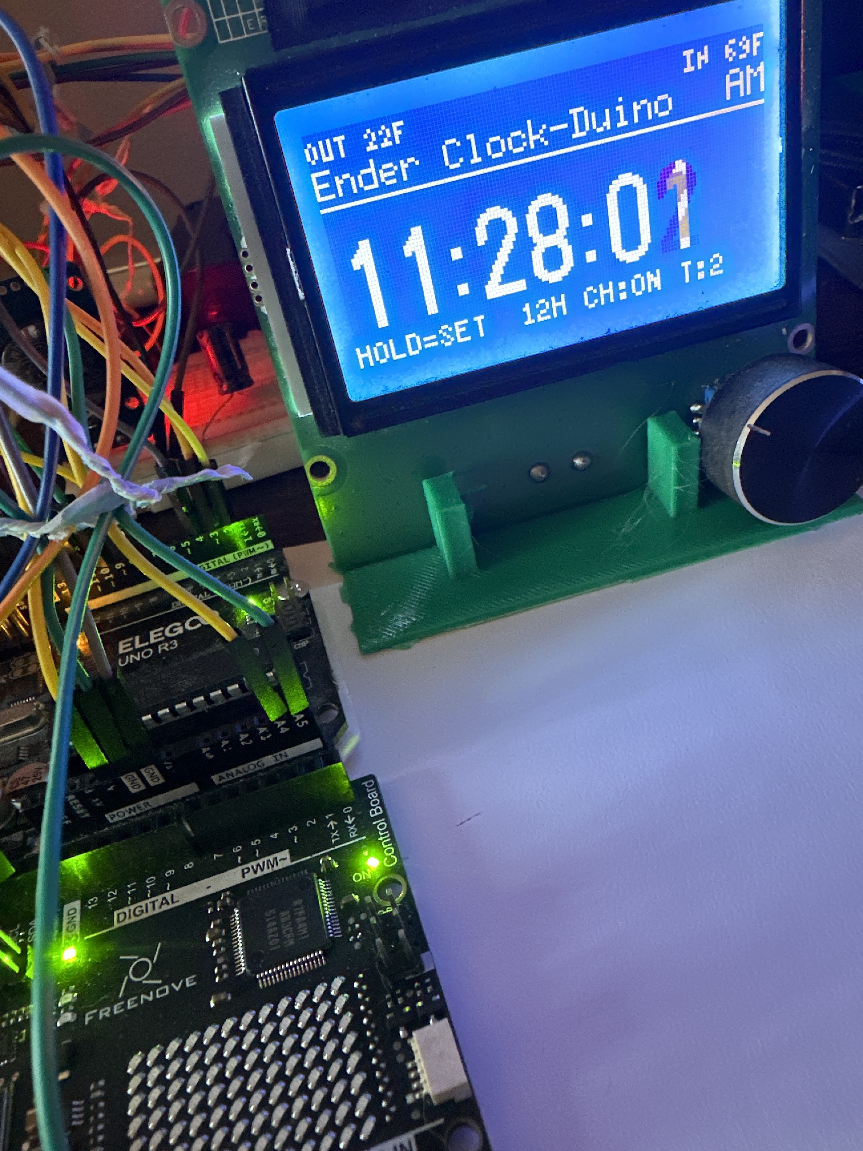
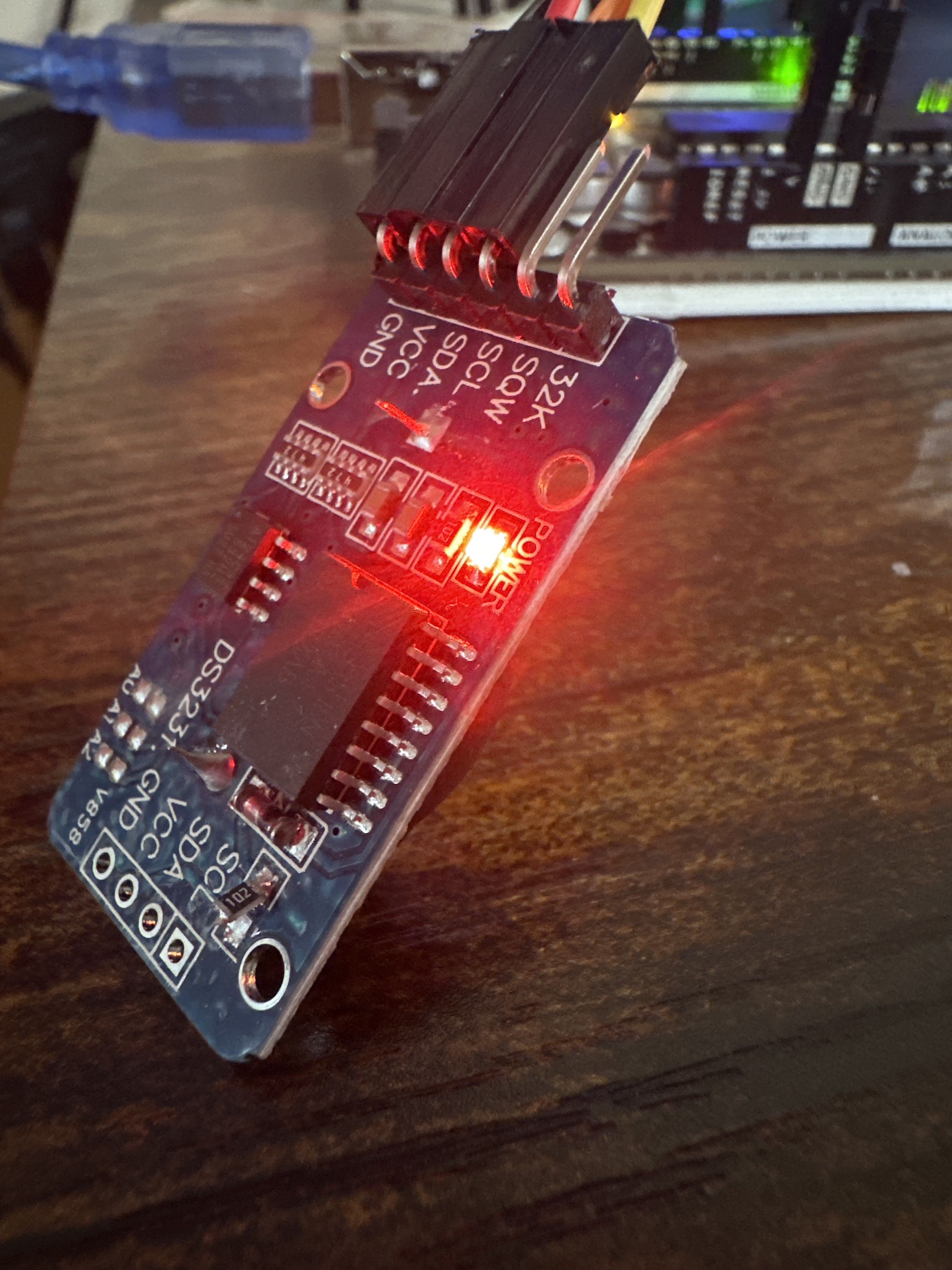
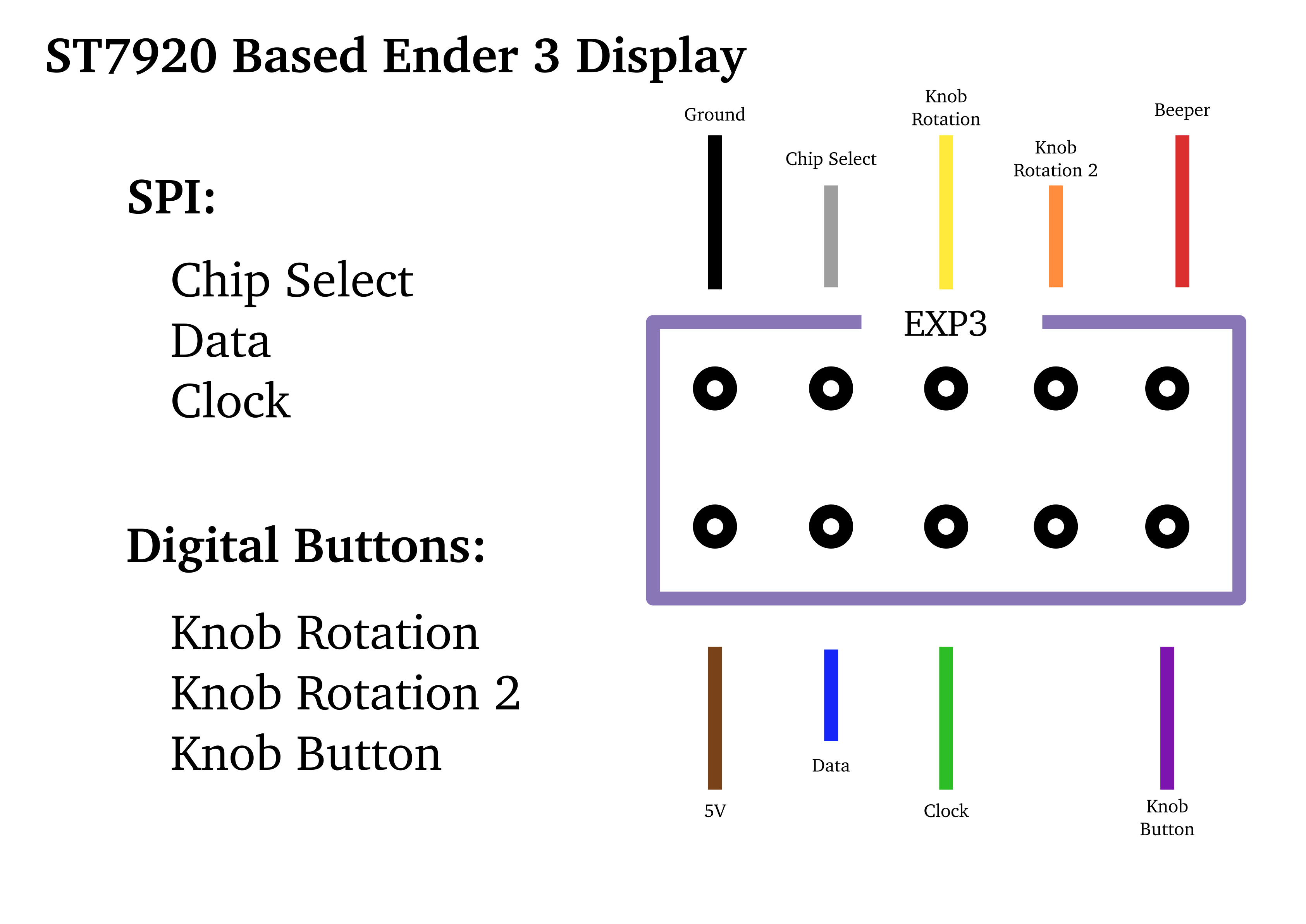
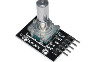
This project uses an Arduino Uno R3 board with an original Ender 3 Pro control panel LCD. The Arduino is driving the ST7920 LCD over hardware SPI and handling the integrated rotary encoder via interrupts for reliable input. Timekeeping is provided by a DS3231 RTC module to maintain accuracy across power loss, while user settings are stored in EEPROM so configuration persists without reentry. Audible feedback is implemented with a piezo buzzer using distinct tone patterns for interaction cues.
Firmware developed collaboratively using AI-assisted code generation, with system architecture, behavior, integration, testing, and refinement by me :)
 stefan.schnitzer
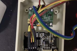
 Ai-Thinker
 agp.cooper