 DeckerEgo
-
1Step 1
![]()
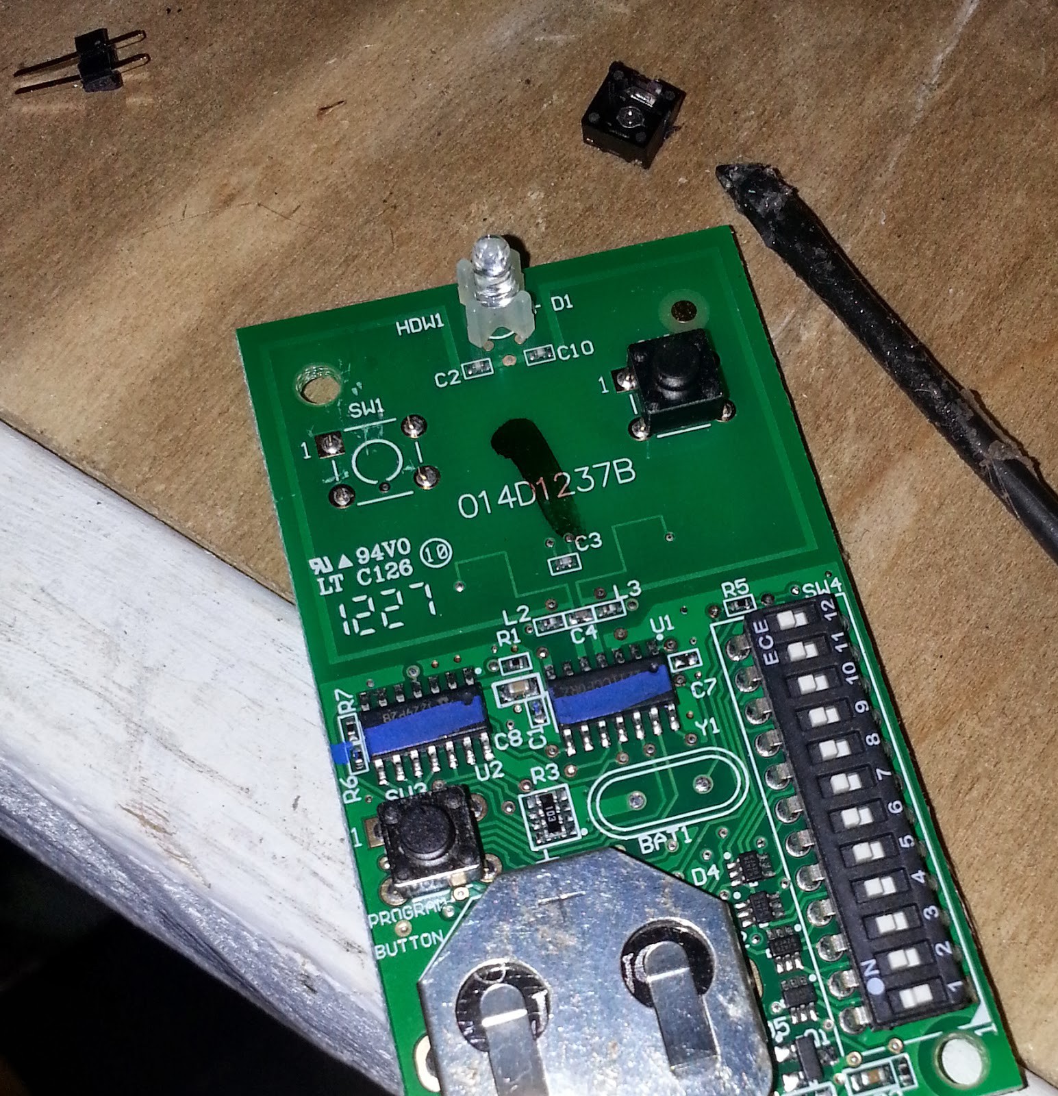
Shuck the universal garage door opener, pulling out the bare circuit board
-
2Step 2
Use a soldering iron to melt the leads for button #1 just enough that the button can be pulled out - you could also reflow the solder and pull out the button.
-
3Step 3
Replace the leads to the button with breadboard pins. For my remote I needed to wire up lead #1 and any other lead to connect the circuit - your milage may vary.
-
4Step 4
![]()
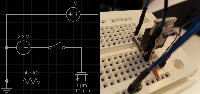
Wire together the exposed leads from the universal remote to a mini-breadboard, and complete the circuit with a pull-down resistor and a MOSFET as detailed in the circuit diagram. Connect the ground (not button #1) lead from the garage door opener to the source pin of the MOSFET, and connect the lead (button #1) pin to the drain pin of the MOSFET.
-
5Step 5
![]()
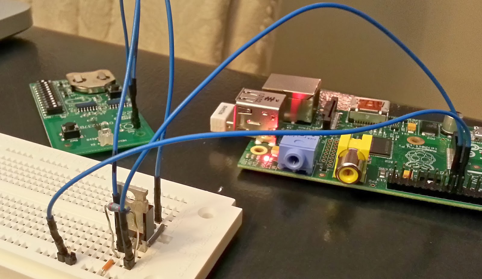
Connect a GPIO pin (I chose GPIO 17) from the Raspberry Pi to the gate pin of the MOSFET.
-
6Step 6
Connect a ground pin (I chose the ground pin next to GPIO 17) to the drain pin of the MOSFET. Bridge the 4.7k pull-down resistor between the gate and drain pins of the MOSFET.
-
7Step 7
You can optionally install the Honeywell HIH6130 I2C breakout to monitor temperature and humidity. This connects over the standard I2C pins on the Raspberry Pi; I used 3V of power however 5V can be used.
-
8Step 8
Follow the software installation instructions at https://github.com/deckerego/GarageSecurity/README.md
Garage Security
A front-end to the Raspberry Pi that uses the NoIR camera & GPIO for remote residential door control
Discussions
Become a Hackaday.io Member
Create an account to leave a comment. Already have an account? Log In.