 NormalL User
Here is a demo of my fast SD card interface for the Ben Eater 6502:
This demo streams uncompressed data at a rate of over 130KBs. I made this after thinking about how I can do better audio for my previous 'Ben
Eater Bad Apple!' Demo for the 6502 and Worlds Worst Video Card.
For my Bad Apple! Demo Version 2.0 I am working on I want to use the PCM audio out of the VIA serial port I was experimenting with recently, https://hackaday.io/project/204469-abusing-a-6522-via-serial-port-for-pcm-audio while also keeping the 30 FPS video I already have working from this earlier Demo with just primitive audio using the 6522 VIA PB7 square wave output.
One of the constraints I have put on myself is only using ‘Official Ben Eater’ chips/hardware, other than a simple SD card adapter and allowing myself a few passives like diodes and resistors.
While it is great that Ben now has added a SID chip (and modern replacements) to the system in recent videos, I am saving a deep dive into the SID for making original music for my 32k ROM based ‘Demo Scene’ style Demo I am also working on. (I had the honor of modifying Monty on the Run by Rob Hubbard for Ben's outro.)
However the math just was not mathing! I was reading too slowly from the SD card. Even with a very fast ‘bit-bang’ routine it was taking over 40 CPU cycles per byte to shift in the data. There just was not enough cycles/SD card transfer speed to do both the video and PCM audio, even at a very low 1,990 bytes/15,920 1 bit samples a second and still keep the 30fps video.
Then a great suggestion from a very smart person lead me to realize that I could rewire the existing PS/2 Keyboard hardware Ben uses and also wire in a couple left over AND gates from Ben’s VGA interface to allow much faster reads from the SD card.
Here is Ben's original video where he goes over this interface:
And here is my re-wired interface for fast SD card reads:
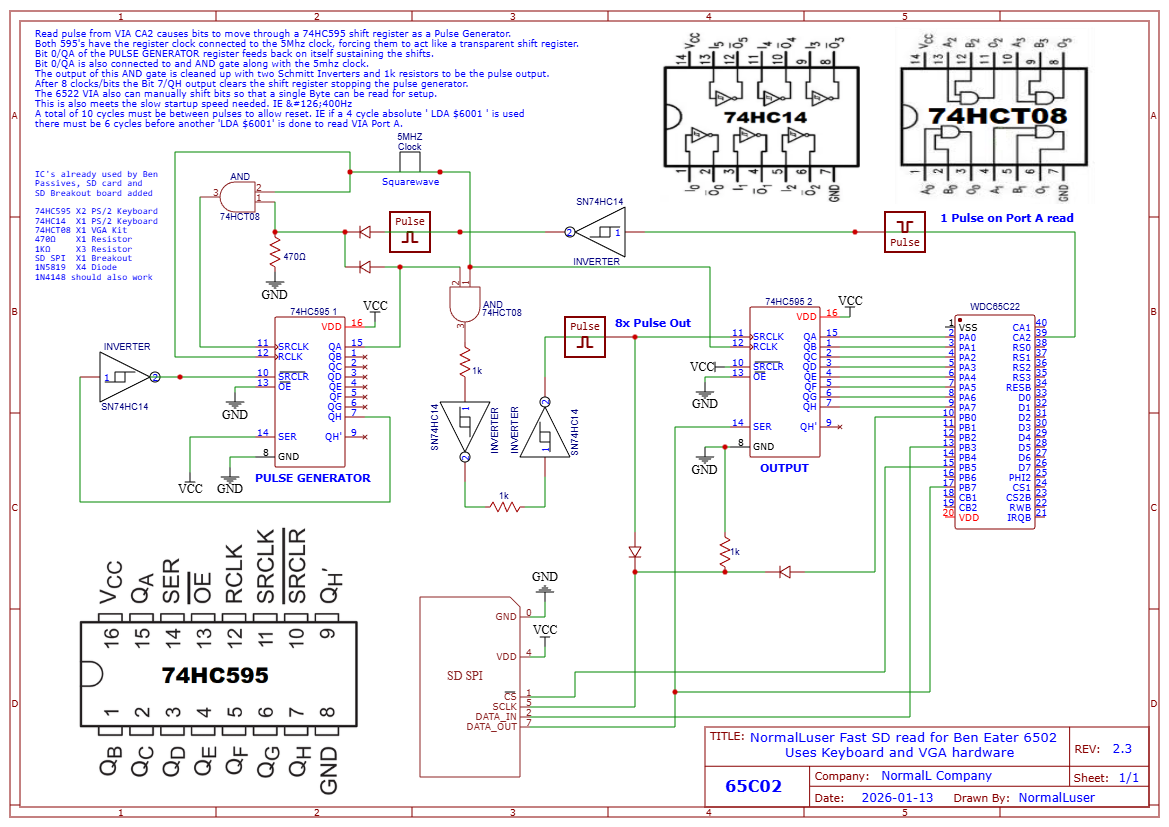
What I ended up doing was using one 74HC595 from the keyboard hardware and connected it to one of the VIA 8 bit parallel ports. This was easy. The tricky part was figuring out how to use other 74HC595 as a ‘Pulse Generator’. VIA Port A is setup to pulse the VIA CA2 pin each time it is read. This is inverted using the 74HC14 from the keyboard hardware and fed into an unused 74CHT08 AND gate from the VGA hardware along with the system clock. This is then fed to the clock input of the ‘Pulse Generator’ 74HC595. This is setup so that the serial input is tied high, and the QA/bit 0 output feeds back to the AND gate CA2 is connected to, keeping the Pulse generator input clock going.
QA/bit 0 is also connected to another unused AND gate along with the system clock. The output of this is cleaned up with resistors and a couple more Schmitt inverter gates from the keyboard hardware and sent along to the SD card clock and the other 74HC595 shift register. This is what clocks in the bits. Cleaning up this signal was key and took the most experimentation.
Since these are ‘latching’ as opposed to ‘transparent’ shift registers the register clock RCLK on both is simply tied to the system clock, forcing them to act more or less like ‘transparent’ shift registers, eliminating the need to have latching circuitry or having to deal with timing of the latching at 5Mhz. My $60 USB oscilloscope was used to the absolute limit to debug this circuitry as it was!
To stop it after exactly 8 bits have been transferred the output of QH/Bit 7 of the pulse generator is sent back through an inverter to the clear pin, SRCLR. This sets the output bits back to low and stops both the clock of the pulse generator itself and the clock output to the SD card/output shift register.
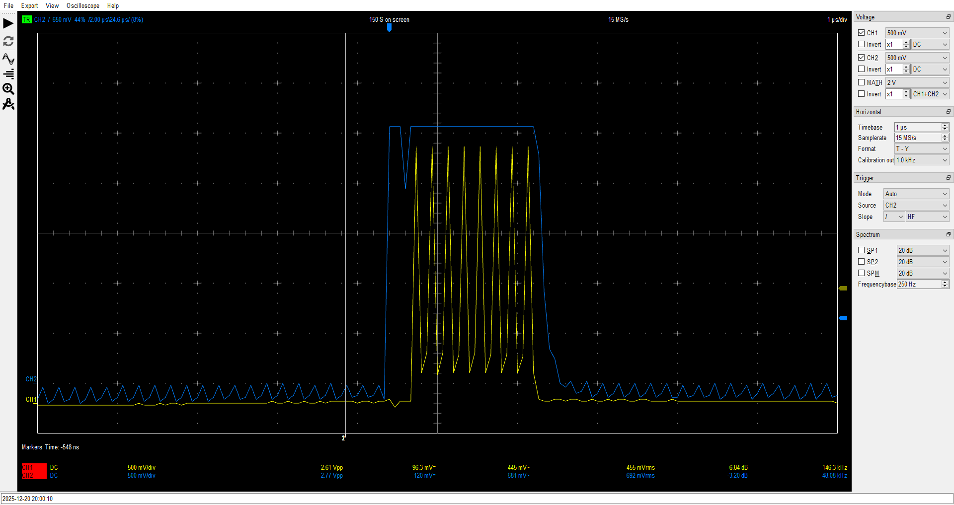
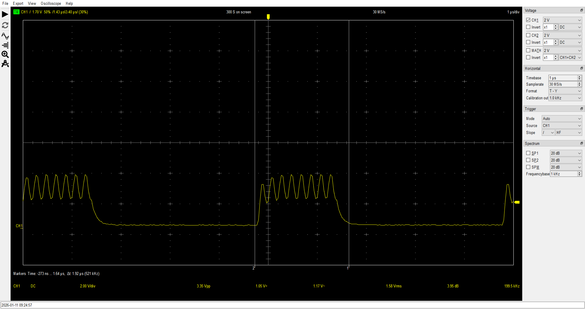
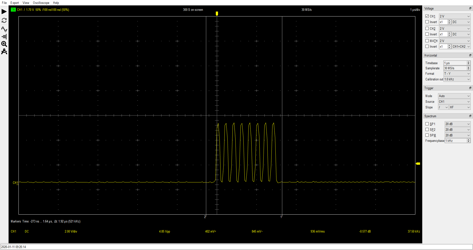
The blue is the output of bit 0 of the shift register that is connected to the AND gate along with the system clock producing the 8 pulses in yellow, after going through the Schmitt inverters and resistors,
... Read more »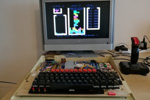
 6502Nerd
 Stephen Moody
 spudfishScott