 GOAT INDUSTRIES
-
1Test which frequency your phone works on
Use a SDR (Software Defined Radio) to find out which frequency band your phone works on. This is actually really good fun and much easier than it sounds. The SDR costs about $24 and can be used with open source software such as GQRX with gives you a pretty amazing spectrum analyser. Check out this video which shows my own cell phone on band 20:
-
2Set up an external antenna
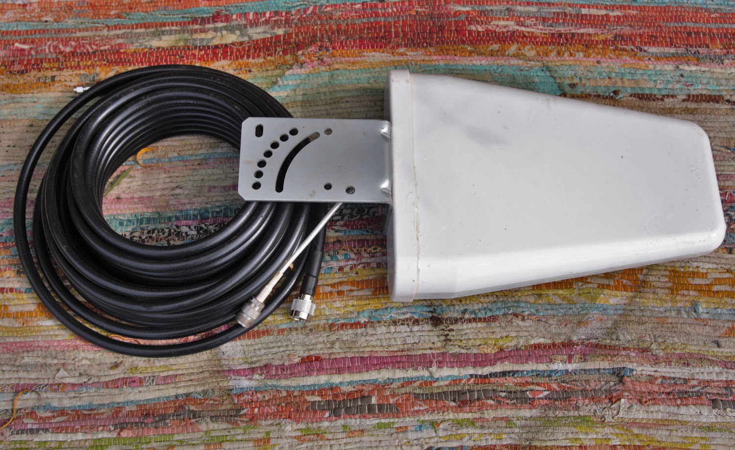
A good quality external antenna arrangement is absolutely essential and the best cable, fittings and antenna should be selected.
![]() The cable should be rated to 0.3 dB loss per metre or better and the antenna should be a Yagi type with performance of 6dB or better. The antenna should be at least 20' in the air, or higher depending on location, and should be pointed directly towards the nearest local 4G transmitter - this can be done by trial and error by swivelling the antenna around and monitoring the results on the SDR.
The cable should be rated to 0.3 dB loss per metre or better and the antenna should be a Yagi type with performance of 6dB or better. The antenna should be at least 20' in the air, or higher depending on location, and should be pointed directly towards the nearest local 4G transmitter - this can be done by trial and error by swivelling the antenna around and monitoring the results on the SDR. -
3Set up the internal antenna
This part is much easier - it's just a panel antenna and it can be mounted on a wall in a convenient location.
![]()
-
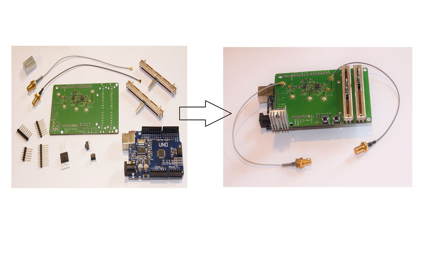
4Assemble the Cell Phone Booster kit
The kit comes with a few 'easy to solder' components, so solder them on, being careful to get the voltage regulator the right way round. The flat part of the regulator faces away from the board.
![]()
-
5Connect the antenna cables
The cables in the kit have female SMA type connections, so make sure that the antenna cables themselves terminate in male SMA with appropriate adapters if required. The kit comes as in the photo above, left, so there are no antenna or heavy cables or adapters supplied.
Make sure there is appropriate strain relief to prevent the heavy cables floating around and destroying the signal booster.
-
6Program the Arduino Uno
Before attaching the Uno to the booster PCB, upload the code. Code for the Arduino is 'Work in Progress', but this simple code will control the booster via the two push buttons. The code could easily be adapted to use the slider instead:
#include "SPI.h" const int slaveSelectPin = 7; // LE for the VGA. const int QPL9065VPD = 3; const int QPL9065VBYP = 4; const int leftButtonPin = A2; const int rightButtonPin = A3; int leftButtonPinValue = 0; int rightButtonPinValue = 0; int leftButtonStatus = 1; int rightButtonStatus = 1; int sensorPin = A5; // select the input pin for the potentiometer float sensorValue = 1.00; int rabbits; void setup() { Serial.begin(9600); Serial.println("Test Begin!"); // set the slaveSelectPin as an output: pinMode(slaveSelectPin, OUTPUT); pinMode(QPL9065VPD, OUTPUT); pinMode(QPL9065VBYP, OUTPUT); // Set QPL9065VPD and QPL9065VBYP both to LOW to enable them both and disable bypass. // digitalWrite(QPL9065VPD, LOW); // digitalWrite(QPL9065VBYP, LOW); // Set QPL9065VPD to HIGH and QPL9065VBYP to LOW to disable them both and disable bypass. digitalWrite(QPL9065VPD, LOW); digitalWrite(QPL9065VBYP, HIGH); } void loop(void) { readPushbuttons(); //sensorValue = analogRead(sensorPin); //sensorValue = 0; delay(1000); //writePotToVGA(); } void readPushbuttons() { // For low power press left hand button. // For high power press right hand button. // For off press both buttons together. leftButtonPinValue = analogRead(leftButtonPin); rightButtonPinValue = analogRead(rightButtonPin); if(leftButtonPinValue==0) { leftButtonStatus = 0;rightButtonStatus = 1; } if(rightButtonPinValue==0) { rightButtonStatus = 0;leftButtonStatus = 1; } if((leftButtonPinValue==0)&&(rightButtonPinValue==0)) { rightButtonStatus = 1;leftButtonStatus = 1; } if(leftButtonStatus == 0) { digitalWrite(QPL9065VPD, LOW); digitalWrite(QPL9065VBYP, HIGH); Serial.println("LOW,HIGH ...... Low power"); } if(rightButtonStatus == 0) { digitalWrite(QPL9065VPD, LOW); digitalWrite(QPL9065VBYP, LOW); Serial.println("LOW,LOW ...... High power"); } if((rightButtonStatus == 1)&&(leftButtonStatus == 1)) { digitalWrite(QPL9065VPD, HIGH); digitalWrite(QPL9065VBYP, HIGH); Serial.println("HIGH,HIGH ....... Everything is OFF"); } } void writePotToVGA() { sensorValue = analogRead(sensorPin); sensorValue = sensorValue*63/1023; rabbits = sensorValue; Serial.println(sensorValue); Serial.println(rabbits); SPI.begin(); digitalWrite(slaveSelectPin, LOW); SPI.transfer(rabbits); digitalWrite(slaveSelectPin, HIGH); SPI.end(); } -
7Attach Uno to the PCB
Disconnect the usb programming cable and attach the Uno to the PCB. Connect a suitable power supply cable of delivering at least 2 amps at either 9v or 12v. 9v is preferable.
Turn on the power supply and reconnect the usb cable if you want to monitor the device through the serial port.
By default, the device is in 'standby' mode with no transmission. Press and hold the left hand button and monitor the response on a cell phone and/or the SDR. Wait a few minutes and if the response is negligible, press and hold the right hand button.
To put the device back into standby, press and hold both the buttons. Simple !
Cell Phone 4G LTE Repeater / Booster / Femtocell
An outside pole mounted aerial picks up 4G signals which are then filtered, amplified and re-transmitted through a second inside aerial.
 The cable should be rated to 0.3 dB loss per metre or better and the antenna should be a Yagi type with performance of 6dB or better. The antenna should be at least 20' in the air, or higher depending on location, and should be pointed directly towards the nearest local 4G transmitter - this can be done by trial and error by swivelling the antenna around and monitoring the results on the SDR.
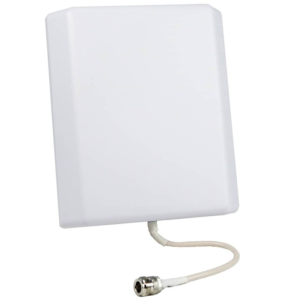
Discussions
Become a Hackaday.io Member
Create an account to leave a comment. Already have an account? Log In.
I'm also interested in buying one of these pre-built, or at the very least, the full kit for a given band or band(s).
Great work/job and I look forward to hearing back!
Are you sure? yes | no
Hi,
Where could I buy the kit? and how much does it cost? I built this profile just to ask this lol
Are you sure? yes | no